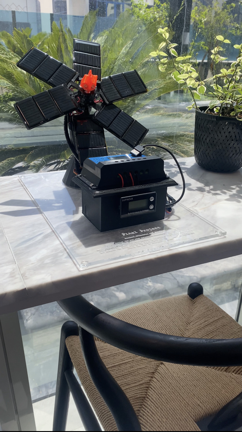
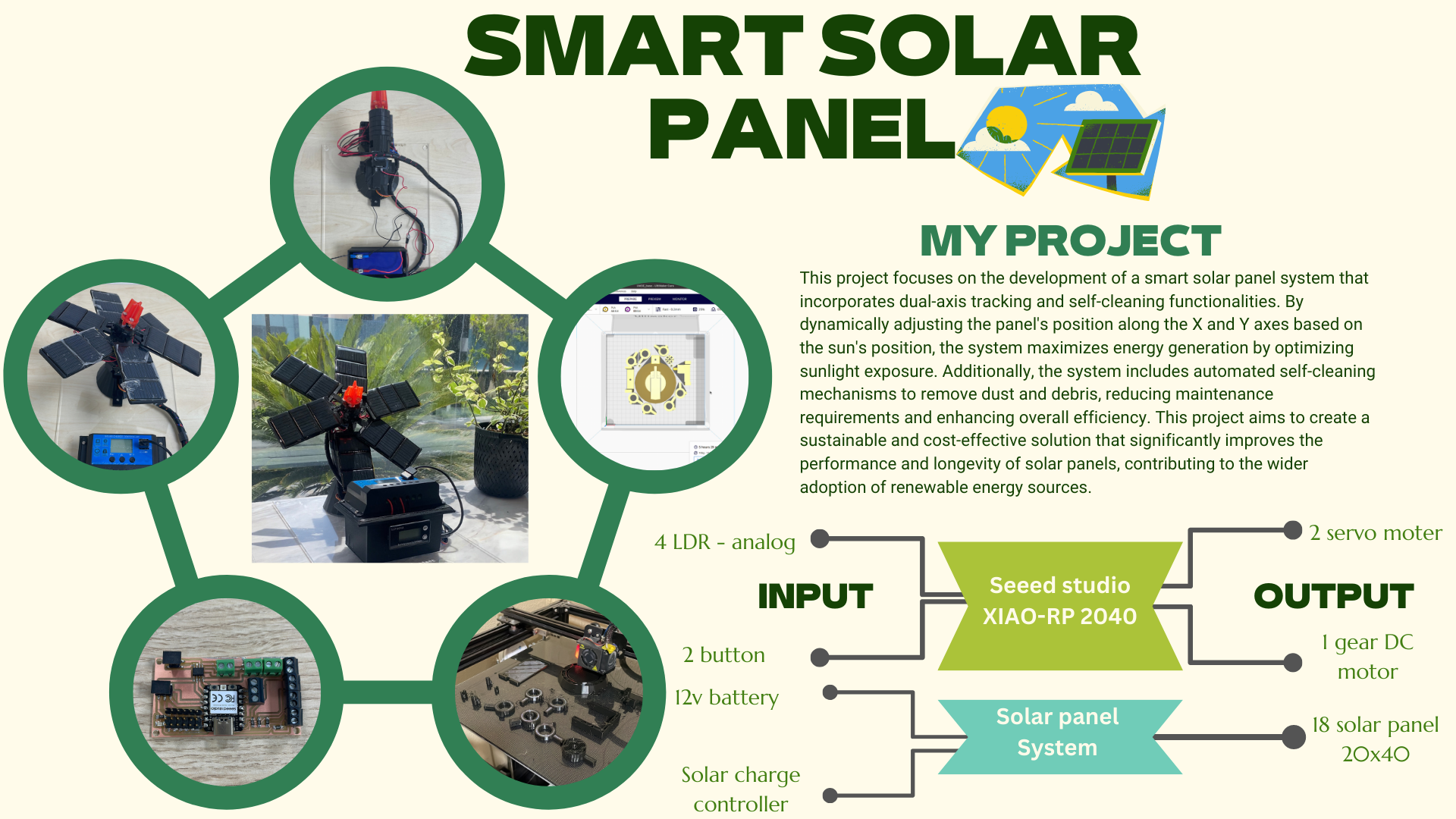
This project focuses on the development of a smart solar panel system that incorporates dual-axis tracking and self-cleaning functionalities. By dynamically adjusting the panel's position along the X and Y axes based on the sun's position, the system maximizes energy generation by optimizing sunlight exposure. Additionally, the system includes automated self-cleaning mechanisms to remove dust and debris, reducing maintenance requirements and enhancing overall efficiency. This project aims to create a sustainable and cost-effective solution that significantly improves the performance and longevity of solar panels, contributing to the wider adoption of renewable energy sources.
Poster
Test the code
Final project idea:
For the final project idea, I really enjoy thinking of new creative ideas. Although this time I have a lot of ideas going into my mind which makes me confused to select one of them. As a Computer Engineering student, I like to join Engineering and Computer and renewable energy, Thus, my final project is to create a solar panel that moves in a dual-axis with Solar radiation. This robot can be beneficial not only for countries with similar climates as the UAE (Sunny climate) but even the countries that have (Cloudy climate) since the solar panel will move with the light source.
This project focuses on the development of a smart solar panel system that incorporates dual-axis tracking and self-cleaning functionalities. By dynamically adjusting the panel's position along the X and Y axes based on the sun's position, the system maximizes energy generation by optimizing sunlight exposure. Additionally, the system includes automated self-cleaning mechanisms to remove dust and debris, reducing maintenance requirements and enhancing overall efficiency. This project aims to create a sustainable and cost-effective solution that significantly improves the performance and longevity of solar panels, contributing to the wider adoption of renewable energy sources.
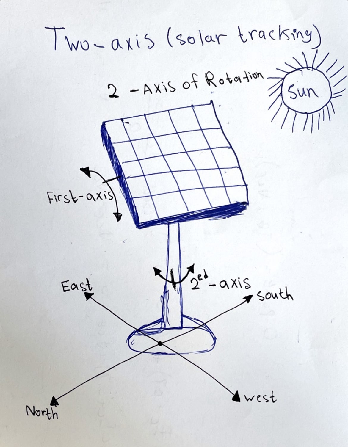
Dual-axis Solar Panel :
1. Sketch:
2. The Function of the project and its uses :
The aim of this project is to absorb the sunlight that emits as much as possible, which will benefit us by producing more and more energy in the same period of time.
Working Principle:
The solar panel will track the light source which is the sun light then the same pross will be on when energy from the sunlight is absorbed by the PV cells in the panel. This energy creates electrical charges that move in response to an internal electrical field in the cell, causing electricity to flow. At the same time the Servos motor will track the light using (Photo resistor) or (Light Dependent Resistor (LDR)).
3. what is the Advantages & Applications :
Advantages of Sun Tracking Solar Panel:
The solar energy can be reused as it is non-renewable resource.
This also saves money as there is no need to pay for energy used (excluding the initial setup cost).
Helps in maximizing the solar energy absorption by continuously tracking the sun.
Sun Tracking Solar Panel Applications:
These panels can be used to power the traffic lights and streetlights.
These can be used in home to power the appliances using solar power.
These can be used in industries as more energy can be saved by rotating the panel.
Working Principle:
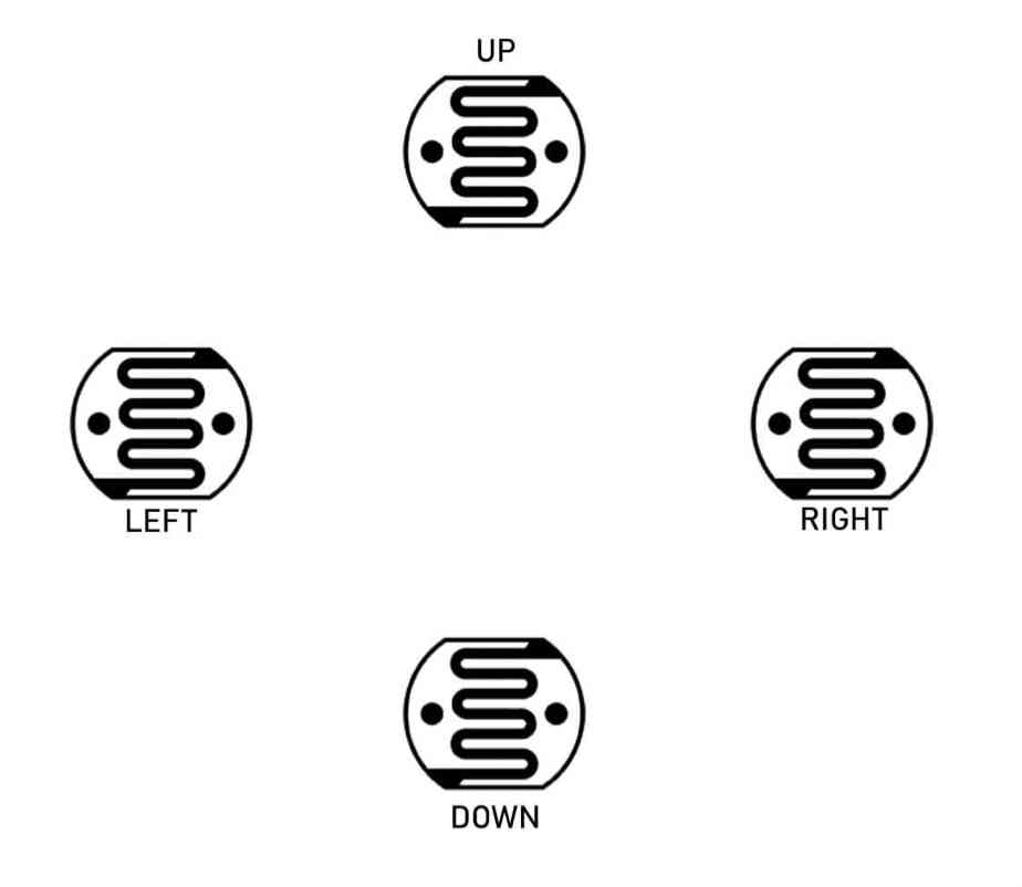
You can see the FOUR resistor is placed on the middle position of the solar top,
when the light is minimum, the micro controller seeed RP2040 read the resistance value and the the threshold value is sated in the coding section, when the light is available and the threshold level breaks, the Arduino rotate the n20 gear motor anticlockwise through the L293D Driver till the limit switch level high, when anticlockwise limit switch pressed the panel stop rotating and panel is fully opened position when the button is pressed, now the main work is going to progress, according the sun rotation other 4 LDRs sense the light and send data to the seeed RP2040, and seeed RP2040 process the data then rotate the servo motors according the sun rotation, the rotation position of the servo is max 170 degrees,when the sun goes down the 4th LDR sense data again and this time the process is reverse condition, the LDR data goes down blow the threshold level and seeed RP2040 Rotate the N20 motor clockwise till the 2nd limit switch press and run the servo in home position, when light is available in next day the same process goes on again.
Questions to Answer
What will it do?
"Smart Solar panel", The project aims to create a smart solar panel system that can move in a dual-axis with solar radiation and includes self-cleaning functionalities as improvment in the future. The main function of the project is to absorb as much sunlight as possible to produce more energy in the same period of time.
Who’s done what beforehand?
The project is called "SMART SOLAR PANEL" and involves creating a dual-axis tracking and self-cleaning system to optimize solar panel efficiency. It uses components like solar panels, LDRs, servo motors, and a gear DC motor. The project is documented by a contributor in a Fab Academy course. The system dynamically adjusts the panel's position based on the sun's movement and incorporates self-cleaning mechanisms. The documentation includes details on components, working principles, advantages, and applications. The project is open-source under a Creative Commons license, allowing sharing and remixing with attribution. Specific prior projects or contributors are not mentioned in the provided text.
What will you design?
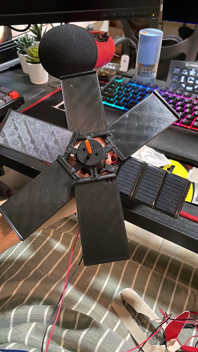
The solar panel holder case itself (3D design).
The electronic circuits needed for the processor, inputs and outputs.
LDR holder
Servo holder for x-axis and y-axis
acrylic base
Electronics box
What materials and components will be used?
The materials and components used in the "SMART SOLAR PANEL" project include:
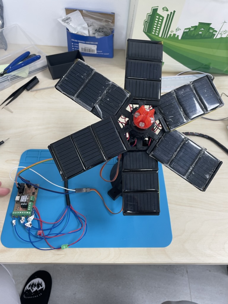
Solar Panels: These are the primary energy-capturing devices.
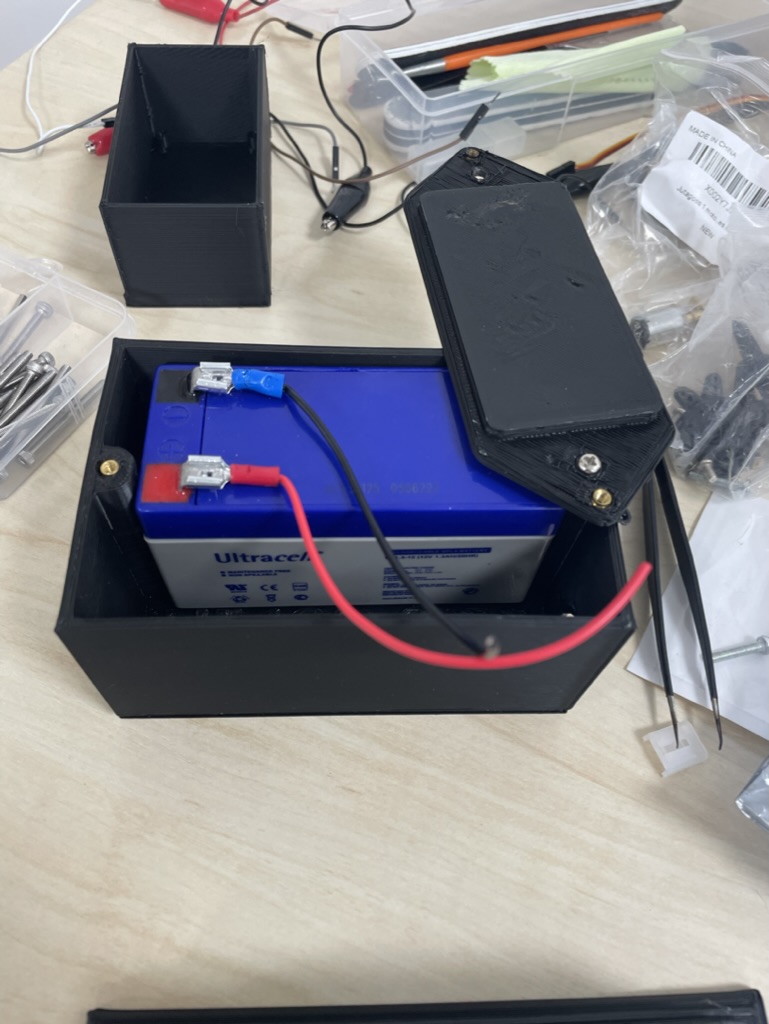
12v 1.2ah battery: to store the power from the solar panel
LDRs (Light Dependent Resistors): These sensors detect the intensity of light and help in tracking the sun.
Servo Motors: Used for the dual-axis tracking system to orient the solar panels toward the sun.
3D printed support Structure: Provides the framework for mounting the solar panels and other components.
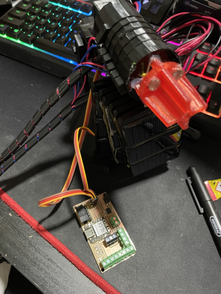
Seed RP2040 microcontroller: Used for processing data and controlling the system.
Wiring and Connectors: Essential for electrical connections between components.
Future improvements:
Gear DC Motor: Employed in the self-cleaning mechanism.
Microfiber Cleaning Cloths: to clean solar panel.
limit switch : to change the Gear DC Motor direction.
These materials and components work together to create a solar panel system that optimizes energy capture through dual-axis tracking and maintains efficiency via a self-cleaning mechanism.
Where will come from? How much will they cost?
Most of the components are already available in the lab. Other elements of the projects will be purchased online or from a local electronics shop if needed.
Qty
Description
Price
Supplier
1
DC Motors
32.00AED
amazon.ae
1
12v 1.2ah battery
31.50AED
amazon.ae
4
LDR
1.20 AED/each
Already exists in the Lab
2
Servo Motors
25.00 AED/each
Already exists in the Lab
18
solar panel 30x60 mm
3.60 AED/each
Already exists in the Lab
1
Acrylic(Matte 3mm + Clear 10mm)
50.00 AED
Already exists in the Lab
1
PLA filament
156.00 AED
Already exists in the Lab
Total cost = ~ 389.1 AED
What parts and systems will be made?
The case and the 3D printed parts
The electronics (PCB, soldering,wires,etc...)
The integrated system
What processes will be used?
Soldering: Connecting electronic components to the circuit board.
Programming: Writing and uploading code to the Seed RP2040 microcontroller to control its functions and interactions with other components.
Mechanical Assembly: Putting together physical components like the servo, DC motor, and limit switch to the 3D printed part to achieve the desired movement or action.
Testing: Verifying that each component works individually and then testing the overall system to ensure proper functionality.
Integration: Bringing together all the components and systems into a cohesive unit.
Power Management: Ensuring the project is designed to efficiently use and manage power, especially with the solar panel and battery.
Quality Control: Checking for any defects or issues in the components and systems to ensure the reliability of the final product.
What questions were answered?
What Algorithms I need to use?
How much will the "Smart solar panel" prototype weight?
How much battery capacity do I need?
servo and gear Dc motor type?
How to let LDR communicate to the servo motor?
How much solar panel I need to supply the battery?
How to display the solar panel voltage?
What sensors I will have?
Can real time processing be done?
What worked? What didn’t?
What worked well in the "Smart Solar Panel" project, is its successful implementation of a dual-axis movement system in response to solar radiation. This innovative design allows the solar panel to dynamically track and maximize sunlight absorption throughout the day, thereby optimizing energy production. The incorporation of such intelligent movement is a commendable achievement.
However, a notable aspect that didn't fully function as intended is the self-cleaning feature, which involves the automated opening and closing of the solar panel. Although this feature is envisioned to enhance efficiency by keeping the solar panel surface clean, it is currently not operational. This serves as a clear area for improvement in future iterations of the project. Addressing this functionality will not only contribute to the project's overall effectiveness but also align with the objective of maintaining optimal energy generation over time.
How will it be evaluated?
The "Smart Solar Panel" will be evaluated based on its proficiency in accurately identifying the sun's direction and effectively tracking sunlight to optimize energy absorption. Additionally, for future the system's will be able to ensure the cleanliness of all panels contribute to its overall evaluation.
What are the implications?
The implications of the "Smart Solar Panel" project are multifaceted and extend to various aspects of energy production, efficiency, and environmental impact.
Energy Efficiency: The successful implementation of dual-axis movement allows the solar panel to dynamically adjust its position, maximizing exposure to sunlight. This, in turn, enhances energy absorption and efficiency, potentially leading to increased power output compared to static solar panels. The implications here are significant for sustainable energy production.
Operational Enhancement: The envisioned self-cleaning feature, although currently not functional, holds the potential to further improve the project's operational longevity. A self-cleaning solar panel would mitigate the impact of dust and debris accumulation, ensuring consistent performance and reducing maintenance requirements.
Environmental Impact: By optimizing energy production, the project contributes to the broader goal of sustainable energy use. This has positive implications for reducing reliance on non-renewable resources and mitigating environmental degradation associated with conventional energy sources.
Technological Advancement:The incorporation of intelligent features like dual-axis movement and the planned self-cleaning mechanism reflects technological innovation in the field of solar energy. This project, with its improvements and future iterations, could serve as a model for more advanced and efficient solar technologies.
Scalability and Adoption:Depending on the success and refinement of the project, there could be implications for scalability and widespread adoption of similar technologies. If proven effective, smart solar panels could become integral components in the shift towards sustainable and renewable energy solutions.
In summary, the implications of the "Smart Solar Panel" project extend beyond its immediate functionality. They encompass advancements in energy efficiency, operational enhancements, positive environmental impact, technological innovation, and the potential for broader adoption of smart solar technologies.
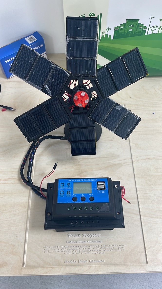
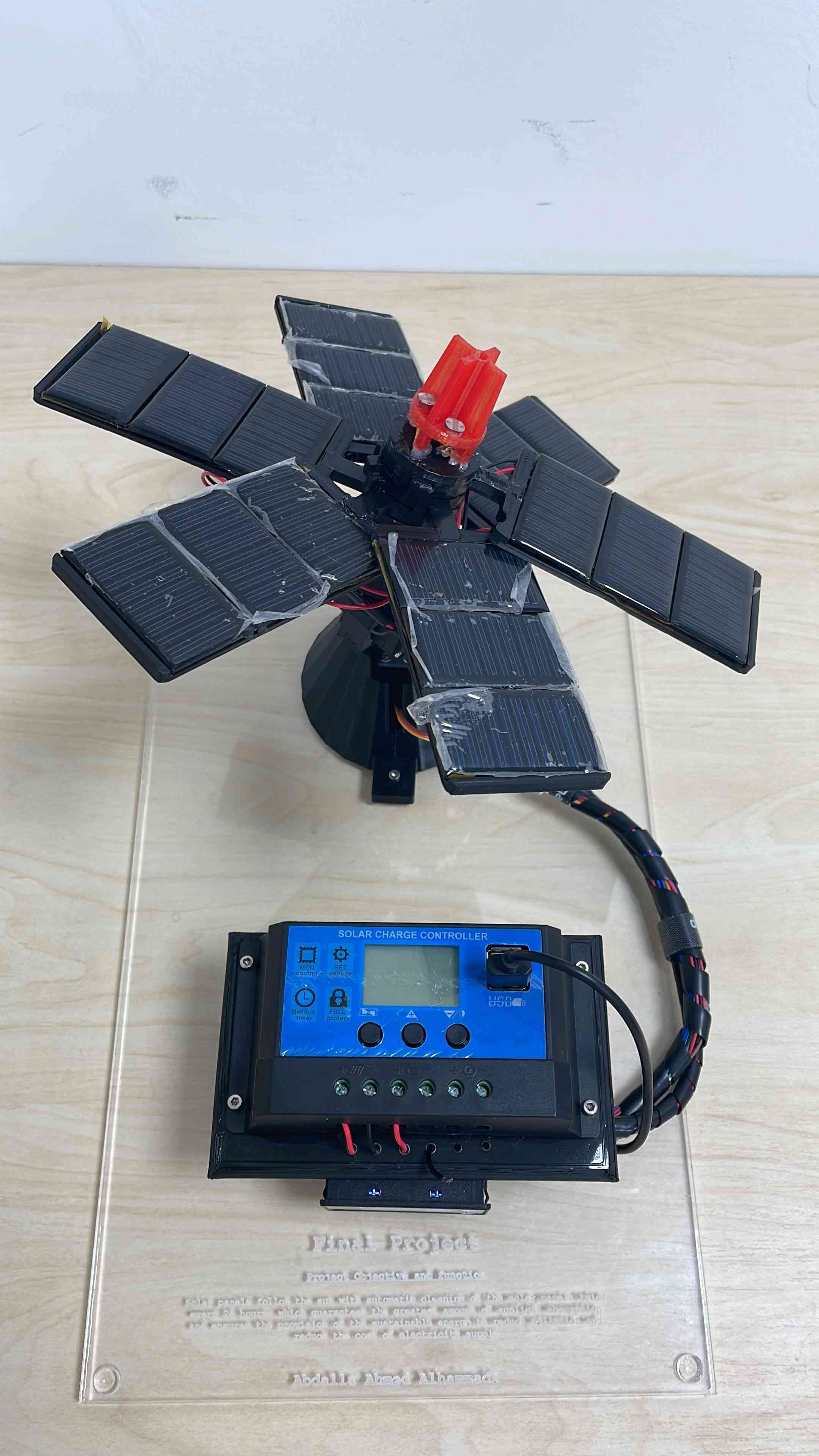
Component:
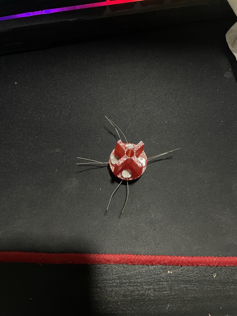
1. LDR:
2. Solar Panel:
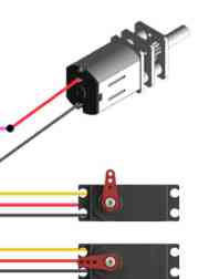
3. Servo and Dc motor :
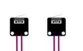
4. limit switch :
Fabrication:
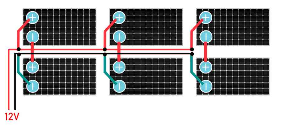
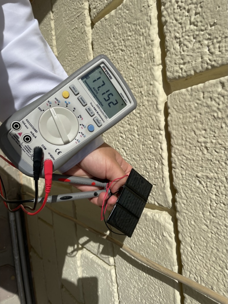
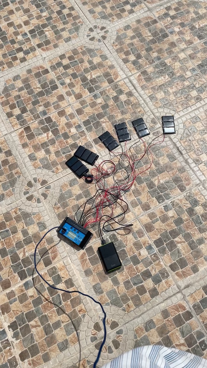
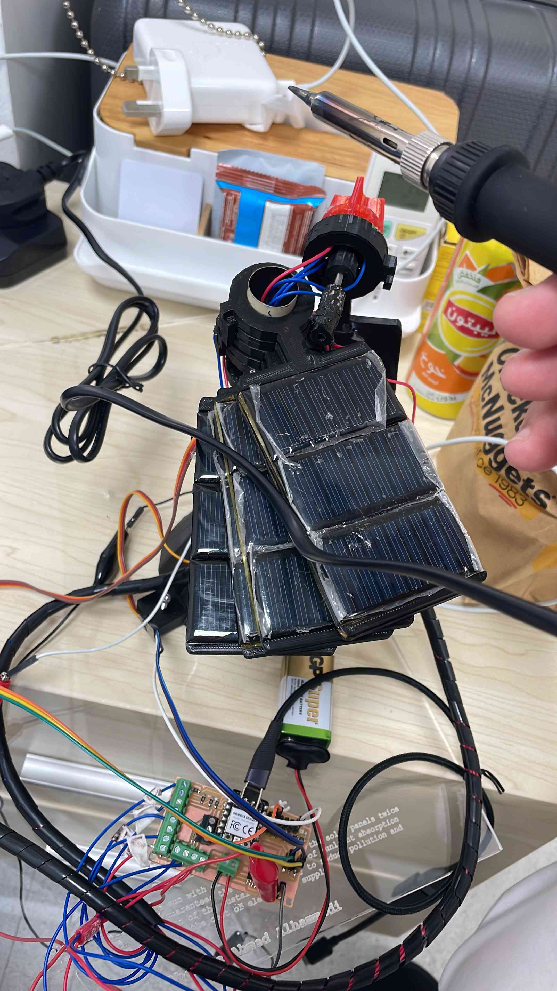
1- I start with testing the solar panel and there total voltage and current.
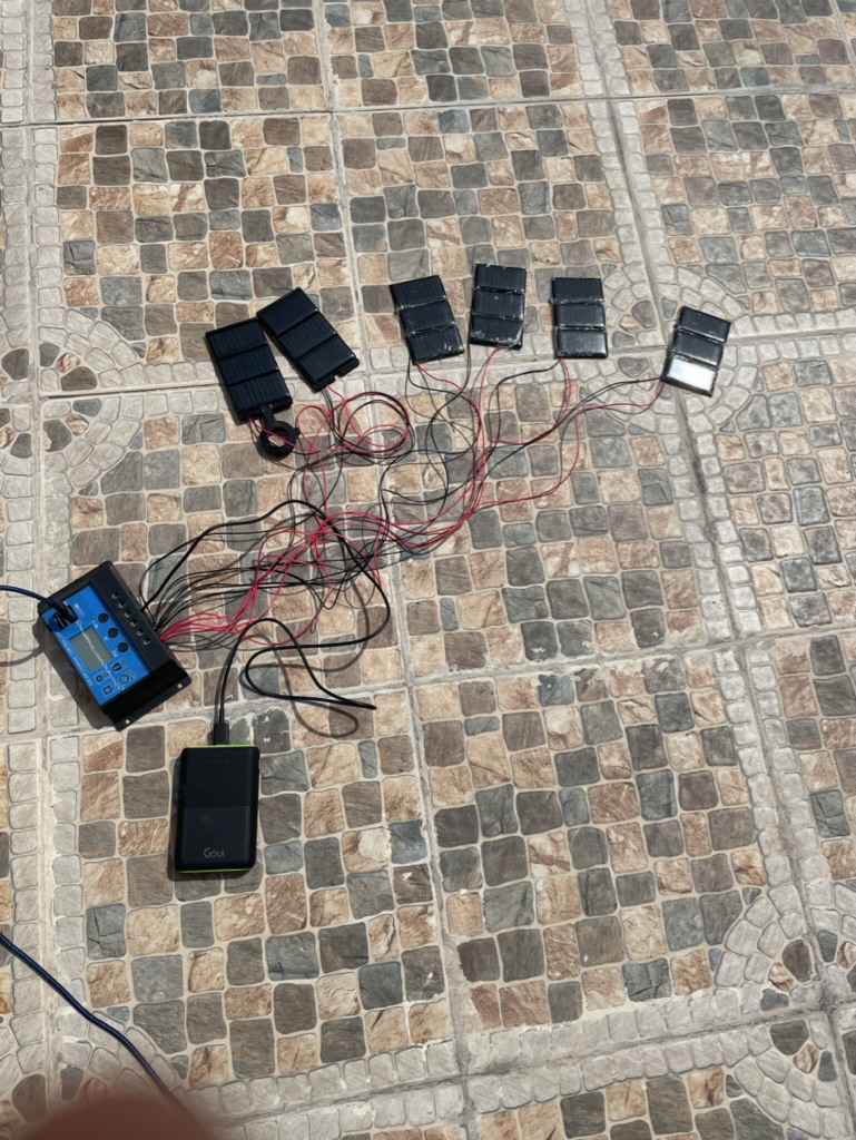
I got arount 17V from 3 panel connected together in series to add all the voltage then to add the current I will connect each set of panel to gether in parallel to add the current
So I decided to connect all the panel like this image
Then I start connecting them
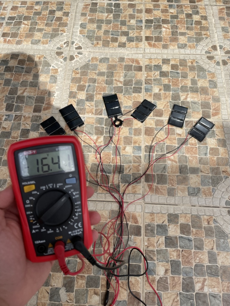
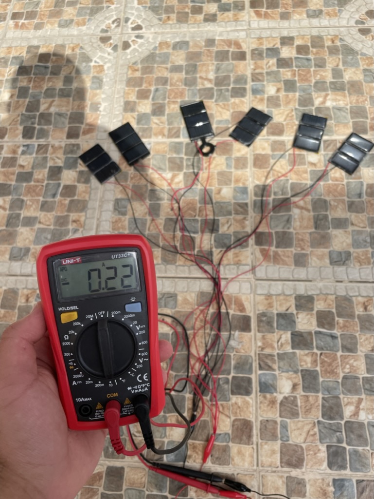
Now I will use the multimeter to measure the voltage and the current for all panel connecting together
I test the solar panels if they an charge my phone and they did, using the USB port on the solar panel controler
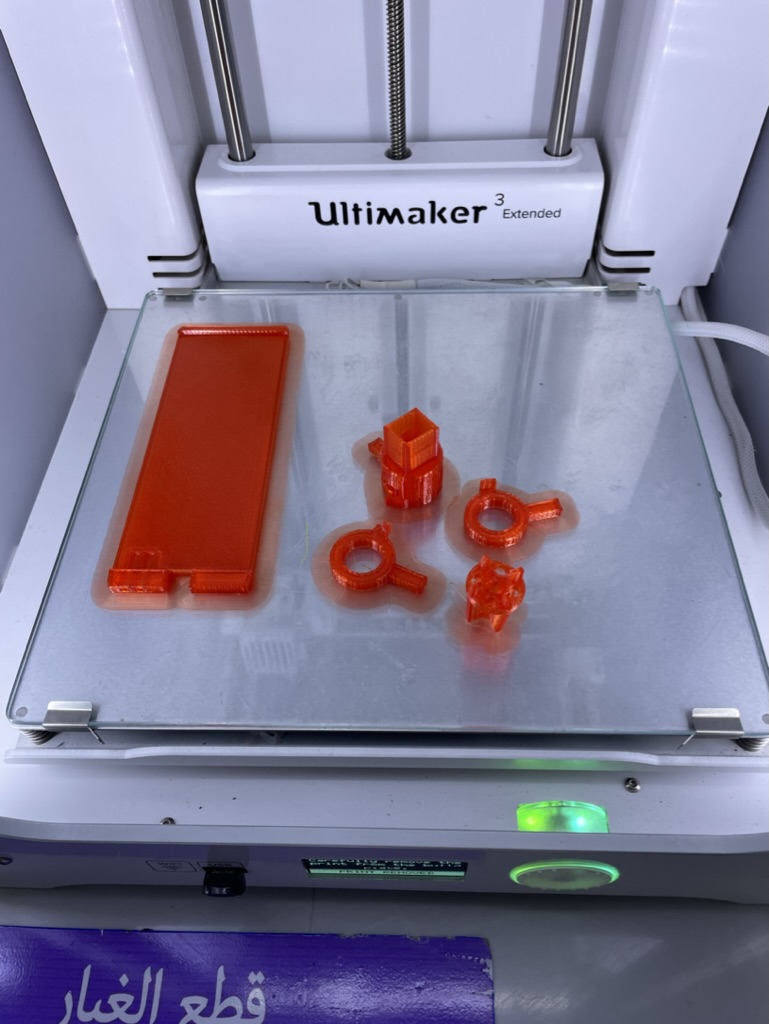
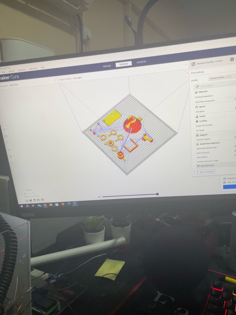
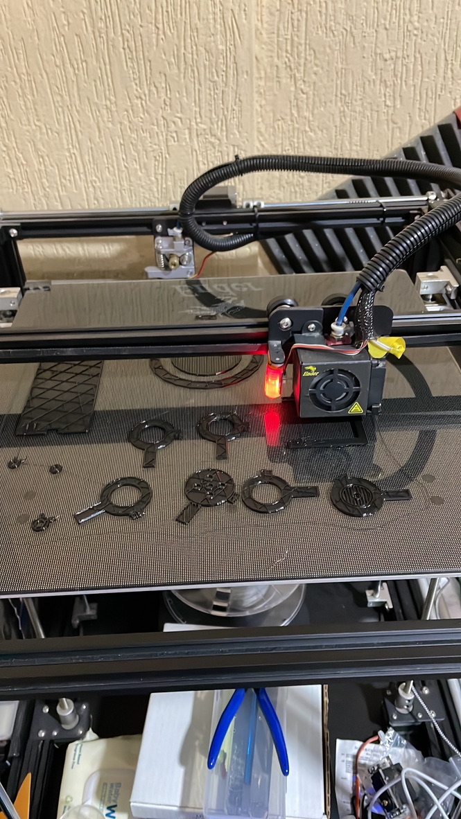
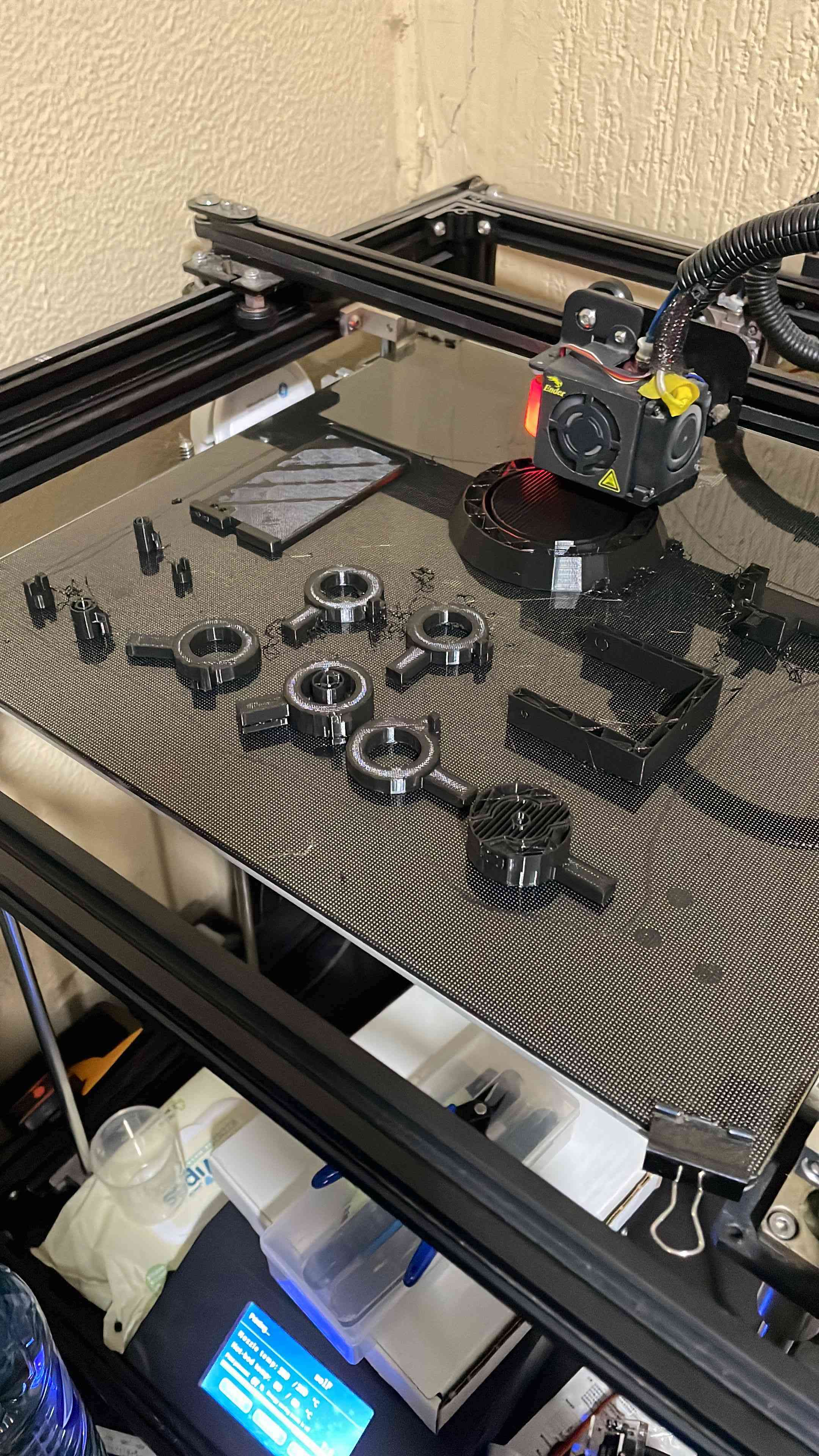
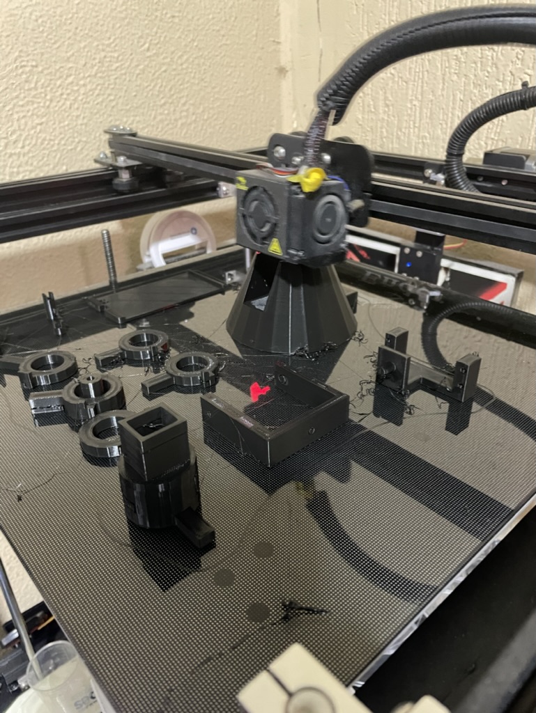
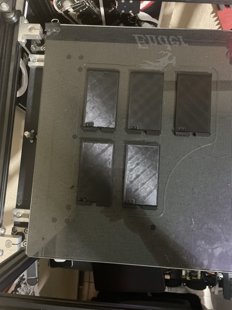
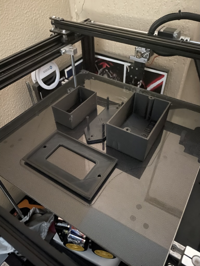
2- 2ed, I start printing the 3D part's
first I start testing the rigth size
Then I printed all the part's
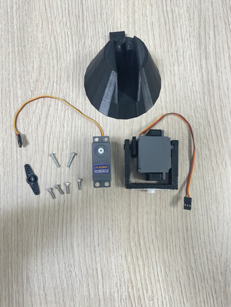
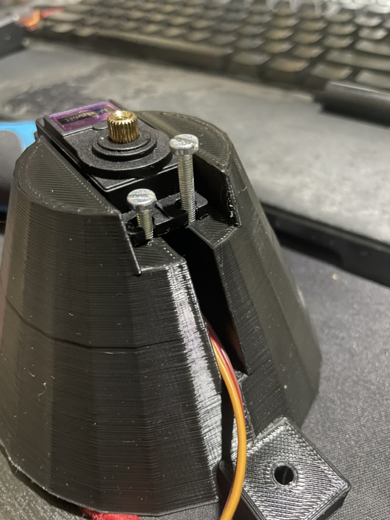
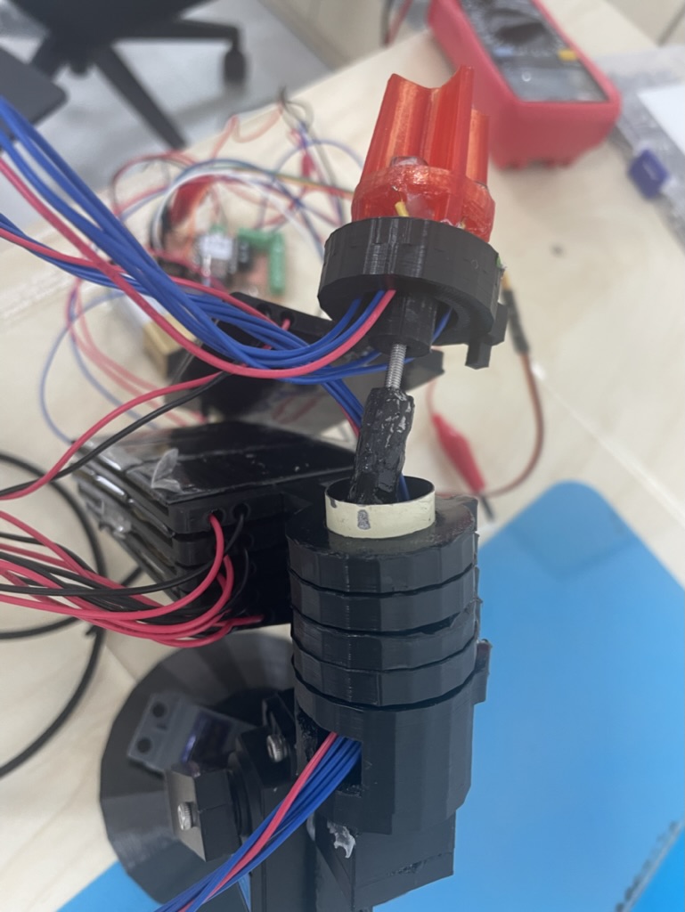
3- Testing the servo motor
first I start connecting the servo moter to the printer parts
Then I test the servo and it movement using simple code
#include "Servo.h"

Servo myservo;  // create servo object to control a servo
// twelve servo objects can be created on most boards

int pos = 0;    // variable to store the servo position

void setup() {
  myservo.attach(D0,540,2400);  // attaches the servo on pin 9 to the servo object
}

void loop() {
    myservo.write(0);              // tell servo to go to position in variable 'pos'
    delay(1000);                       // waits 15ms for the servo to reach the position
    myservo.write(90);
    delay(1000);                       // waits 15ms for the servo to reach the position
    myservo.write(180);
    delay(1000);
  }
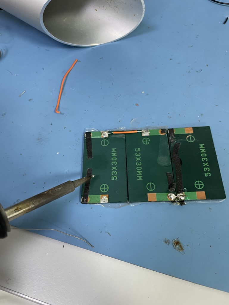
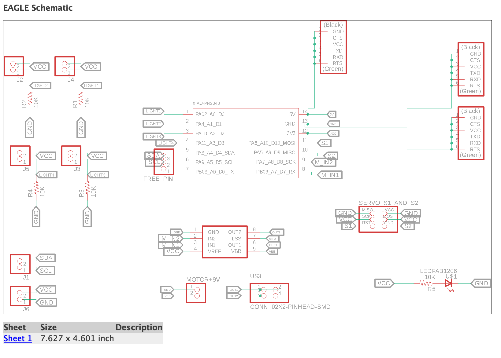
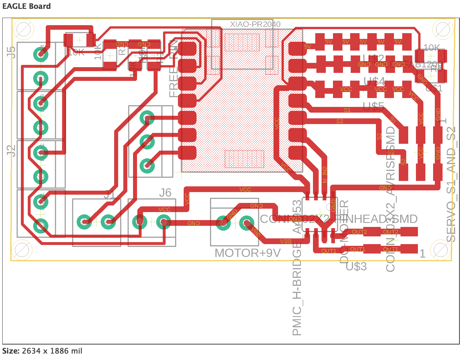
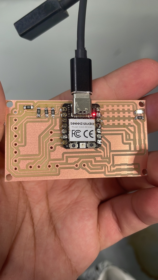
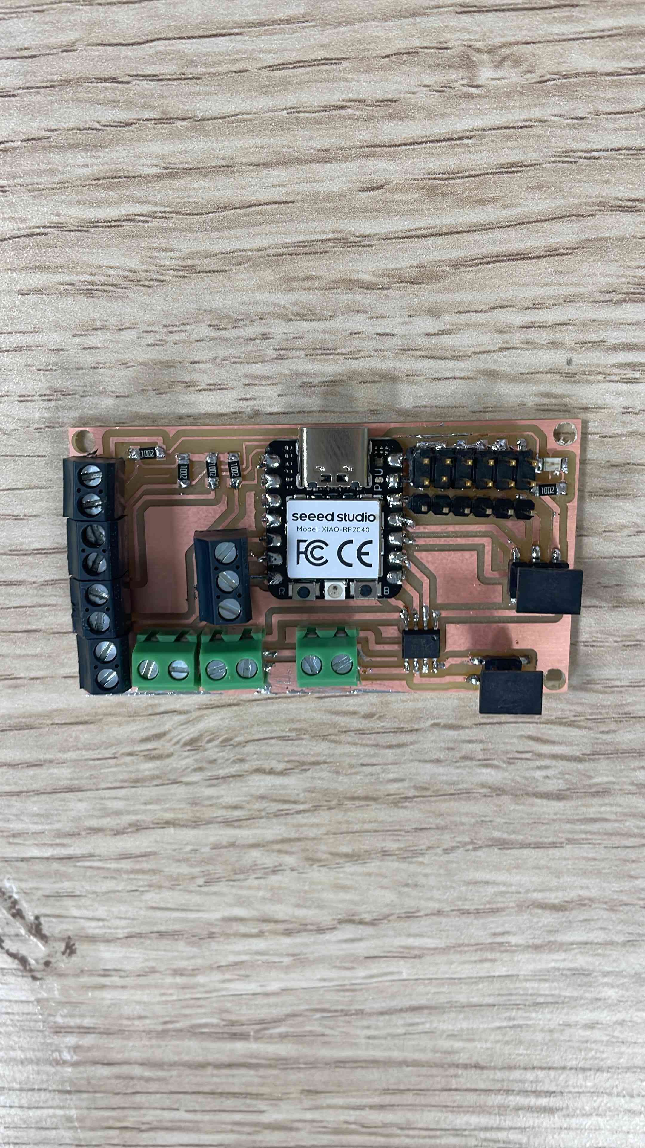
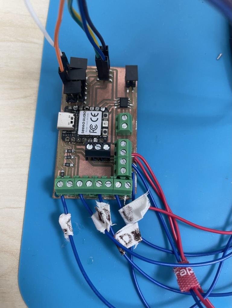
3- Cut the PCD and solder it
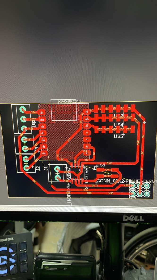
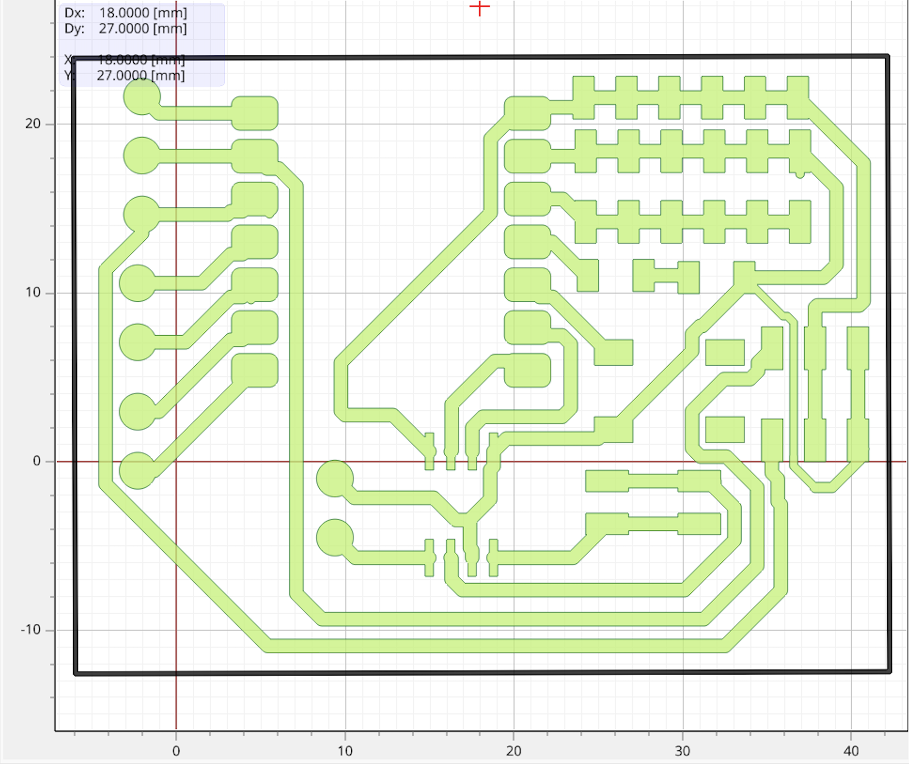
Eagle design
after cutting the board I start solidering
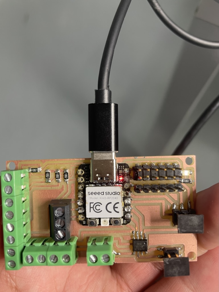
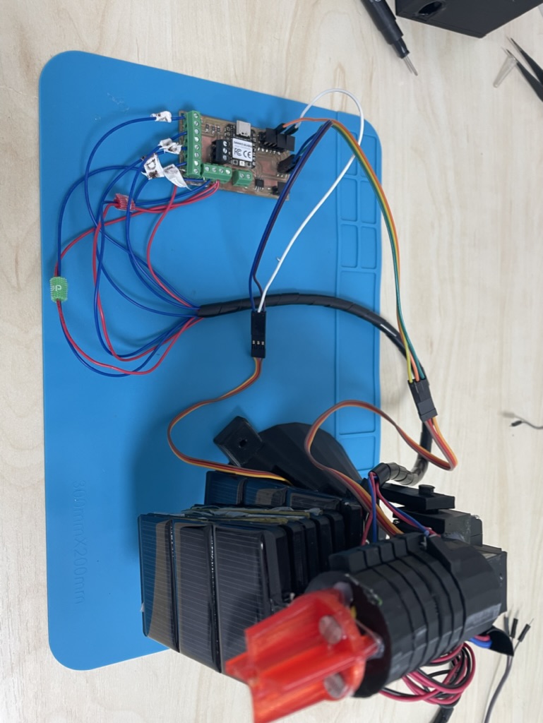
4- Connecting everything together to finalize the project
I start connect the LDR
Then the power box
Testing the panel holder
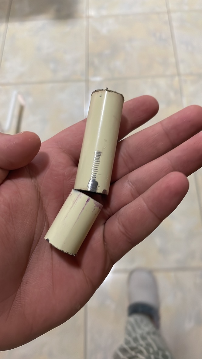
The I cut a small metal rod
and I connected to hold the solar panel holders
start the wiring
and before that I test the servo and the LDR
And before conclude the project I cut an acrylic sheet to hold all the project together
Then I test every thing before closing the power box
And double chick the final wiring
Final project is Done.
Code:
#include "Servo.h"

Servo horizontal; // horizontal servo
int servoh = 180;
int servohLimitHigh = 175;
int servohLimitLow = 5;

Servo vertical; // vertical servo
int servov = 0;
int servovLimitHigh = 60;
int servovLimitLow = 0;

// LDR pin connections
// name = analogpin;
int ldrlt = A3;
int ldrrt = A0;
int ldrld = A2;
int ldrrd = A1;

const int button1 = 7;
const int button2 = 6;
const int motorA = D8;
const int motorB = D7;
int buttonStateA;
int buttonStateB;

int pos = 0;
int pos2 = 0;
int oldvalue;
int oldvalue2;

void setup() {
  horizontal.attach(3);
  vertical.attach(4);
  horizontal.write(180);
  vertical.write(0);
  pinMode(motorA, OUTPUT);
  pinMode(motorB, OUTPUT);
  pinMode(button1, INPUT);
  pinMode(button2, INPUT);
  delay(2500);
}

void loop() {
  int ldrStatus = analogRead(ldrlt);
  if (ldrStatus > 30) {
    buttonStateA = digitalRead(button1);
    if (buttonStateA == LOW) {
      digitalWrite(motorA, 255); // Counter-clockwise
      digitalWrite(motorB, LOW);
    } else {
      digitalWrite(motorA, LOW);
      digitalWrite(motorB, LOW);
    }

    int lt = analogRead(ldrlt);
    int rt = analogRead(ldrrt);
    int ld = analogRead(ldrld);
    int rd = analogRead(ldrrd);
    int dtime = 10;
    int tol = 90; // dtime = difference time, tol = tolerance
    int avt = (lt + rt) / 2; // average value top
    int avd = (ld + rd) / 2; // average value down
    int avl = (lt + ld) / 2; // average value left
    int avr = (rt + rd) / 2; // average value right
    int dvert = avt - avd; // check the difference of up and down
    int dhoriz = avl - avr; // check the difference of left and right

    if (-tol > dvert || dvert > tol) {
      if (avt > avd) {
        servov++;
        if (servov > servovLimitHigh) {
          servov = servovLimitHigh;
        }
      } else if (avt < avd) {
        servov--;
        if (servov < servovLimitLow) {
          servov = servovLimitLow;
        }
      }
      vertical.write(servov);
    }

    if (-tol > dhoriz || dhoriz > tol) {
      if (avl > avr) {
        servoh--;
        if (servoh < servohLimitLow) {
          servoh = servohLimitLow;
        }
      } else if (avl < avr) {
        servoh++;
        if (servoh > servohLimitHigh) {
          servoh = servohLimitHigh;
        }
      } else if (avl == avr) {
        delay(10);
      }
      horizontal.write(servoh);
    }
    delay(dtime);
  } else {
    oldvalue = horizontal.read();
    oldvalue2 = vertical.read();
    for (pos = oldvalue; pos <= 180; pos += 1) {
      horizontal.write(pos);
      delay(15);
    }
    for (pos2 = oldvalue2; pos2 <= 0; pos2 += 1) {
      vertical.write(pos2);
      delay(15);
    }
    buttonStateB = digitalRead(button2);
    if (buttonStateB == LOW) {
      digitalWrite(motorA, LOW); // Clockwise
      digitalWrite(motorB, 255);
    } else {
      digitalWrite(motorA, LOW);
      digitalWrite(motorB, LOW);
    }
  }
}

