Group project
In the beginning, the team was looking for a machine that shows our capabilities. We decided to go with sand drowing machine. Before starting the project, we decided to divide the two weeks. The first week was dedicated to designing the machine and the second week was dedicated to assembling the design.
project discerption
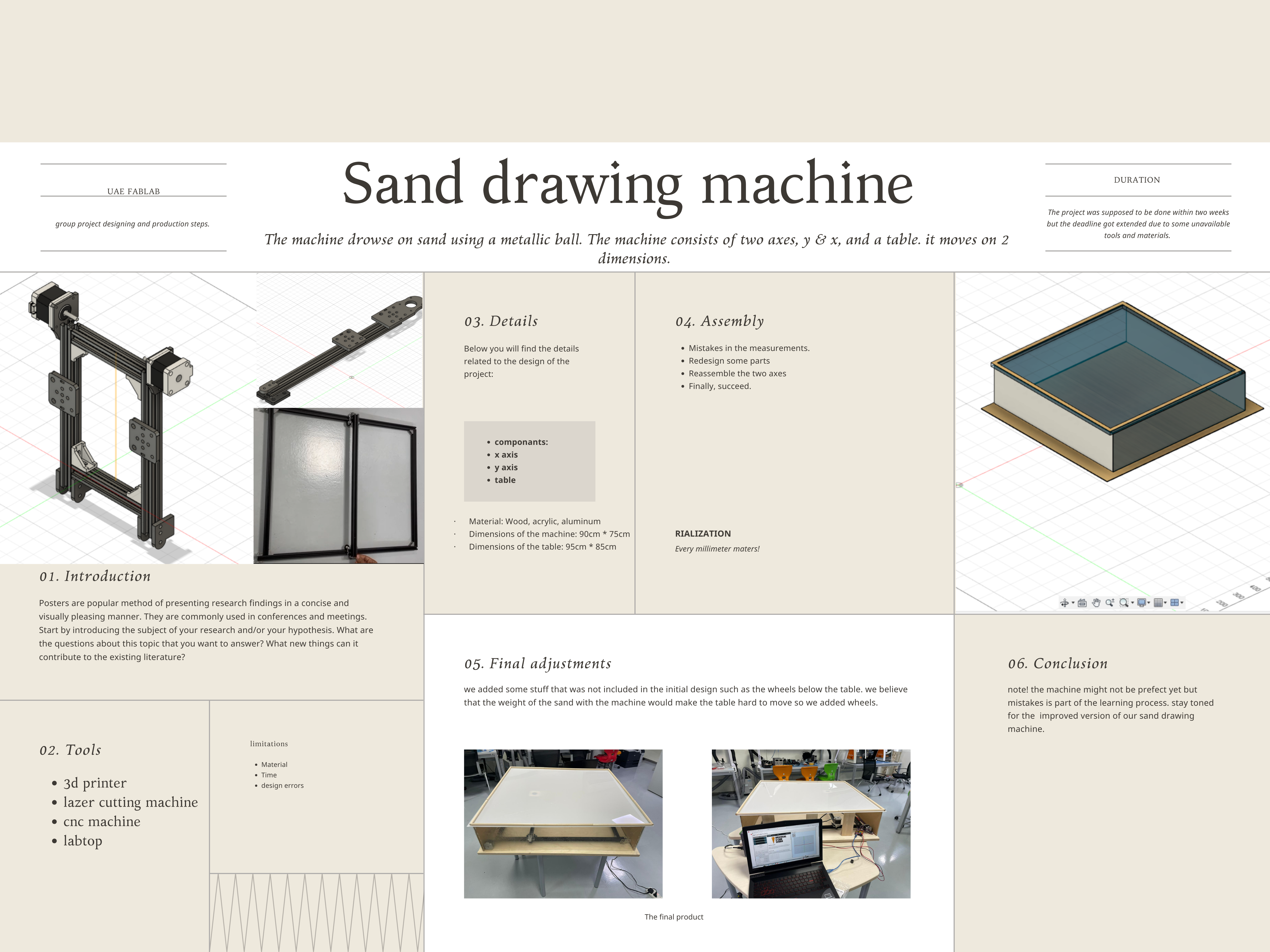
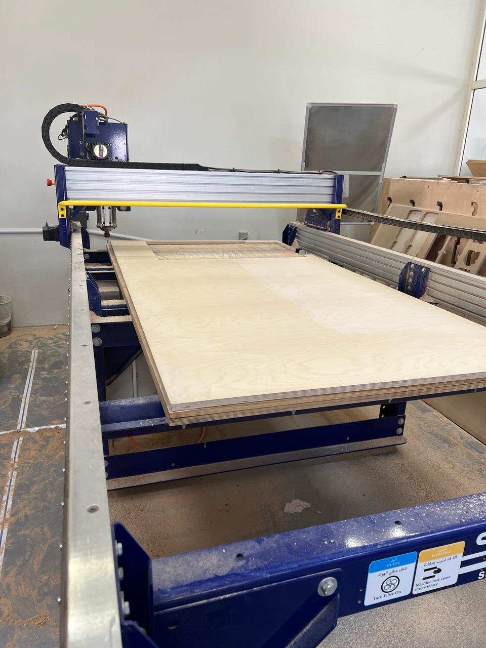
The machine consists of two axes, y & x, and a table. The team members divided the work among themselves. They designed the x-axis, the y-axis, and the table using Fusion 360. Abdulla took care of designing the x-axis and Bashyer designed the y-axis. After finalizing the design and the dimensions of the machine, we were finally able to design a table that is simple, looks good, and suits the machine.
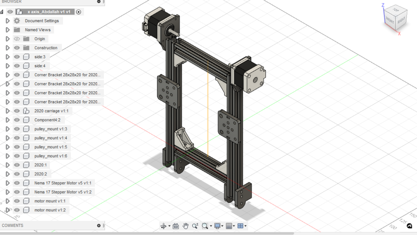
(x,y) axis design
Below you will find the details related to the design of the project
• Material: Wood, acrylic, aluminum
• Dimensions of the machine: 90cm * 75cm
• Dimensions of the table: 95cm * 85cm
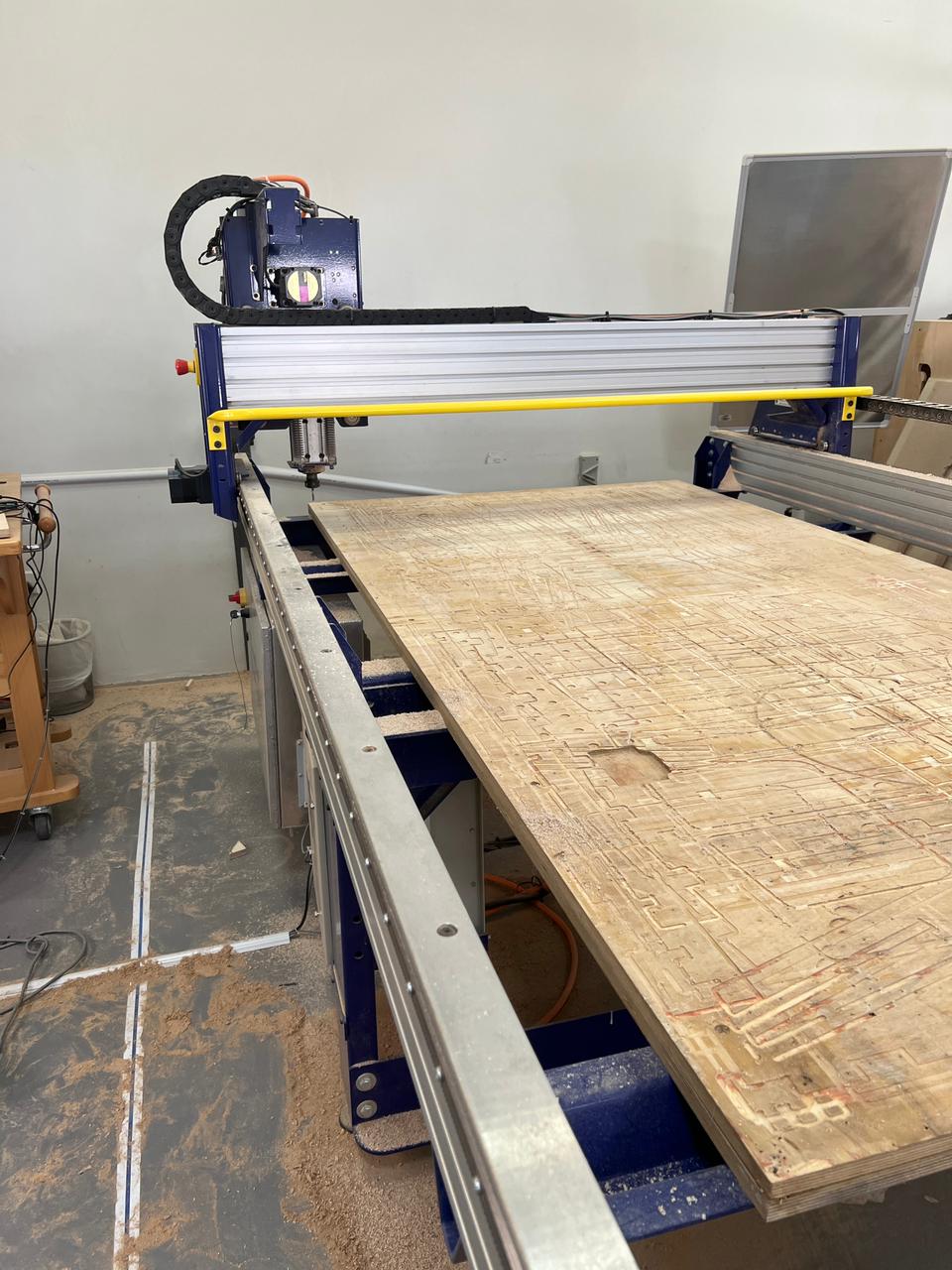
step 1: Laser cutting the Design
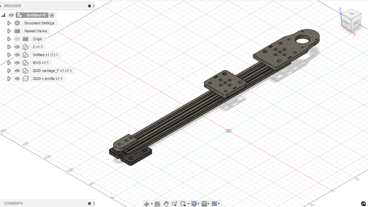
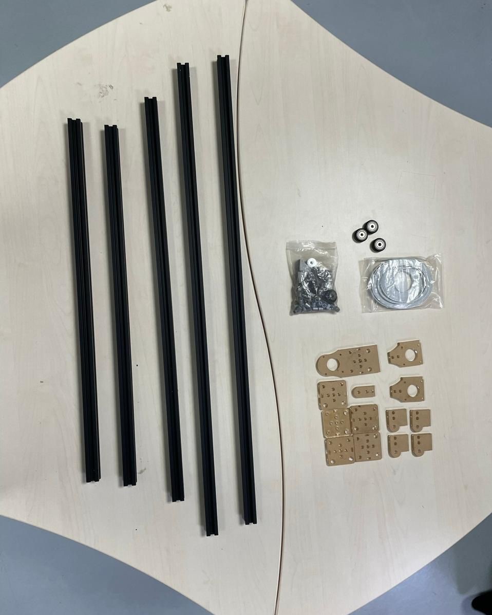
We started working on the project. The first step, making all the dxf files needed for laser cutting. This task took us a couple of hours. Since We had to redo one part needs a tiny adjustment to one peace so we made some changes and recut the motor holed in the y-axis. The material we used so far is 3 mm acrylic. In addition, we went to the workshop to cut the 20 mm*20mm aluminum t-slot profile.
Ready for laser cutting
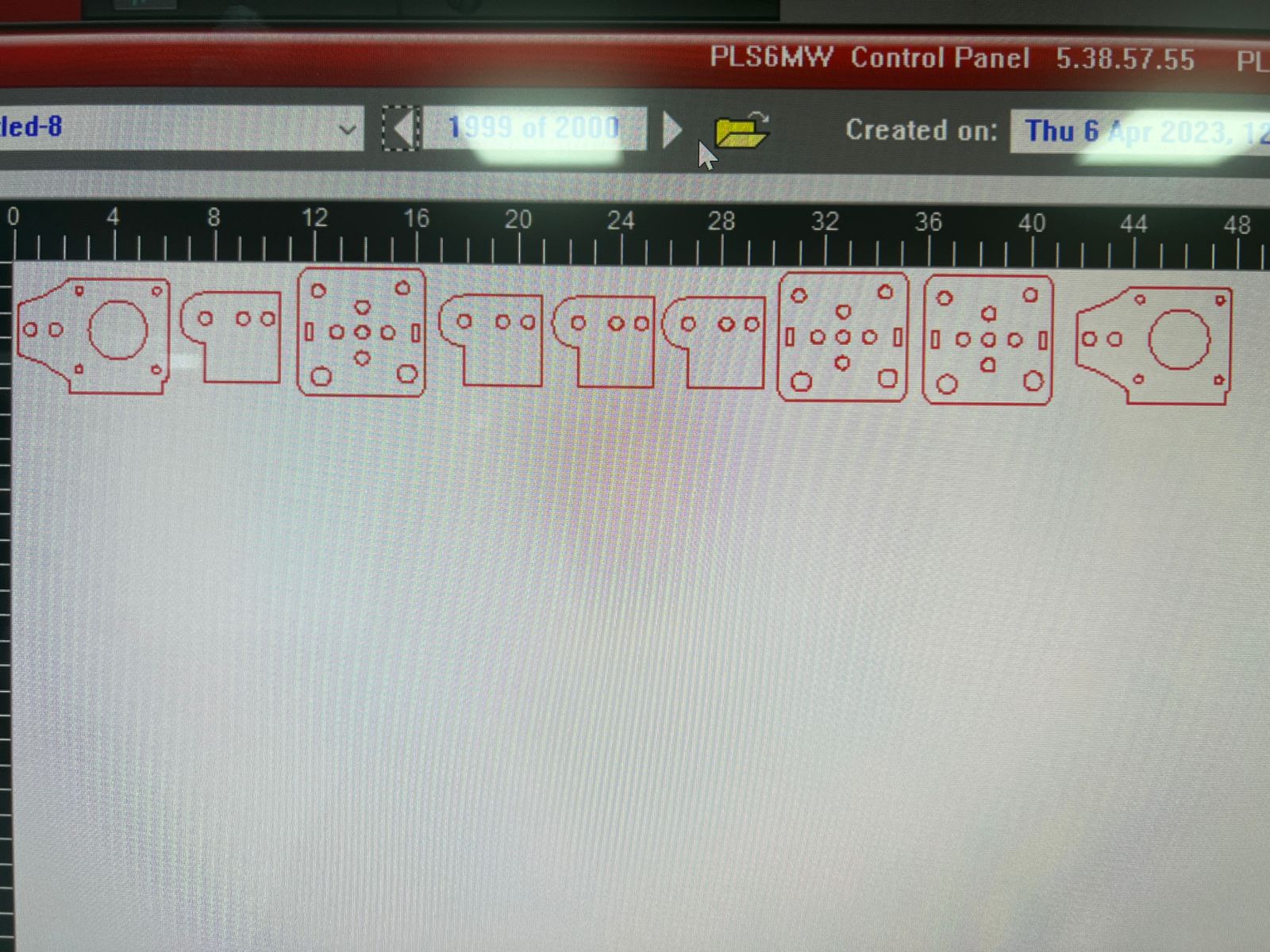
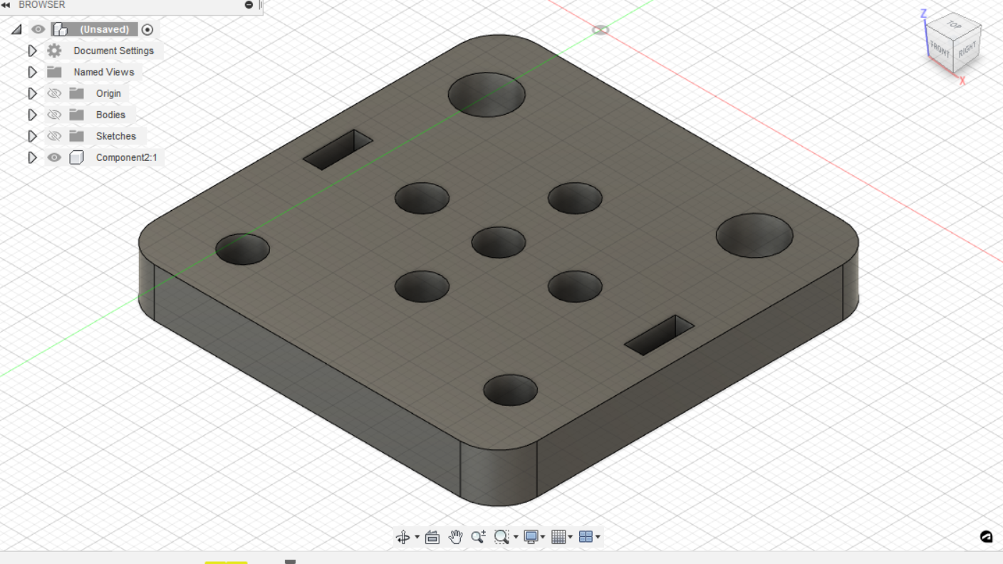
parts made by lazer cutting:
This part is the x-axis pully holder - & it's level up the fram on the plywood
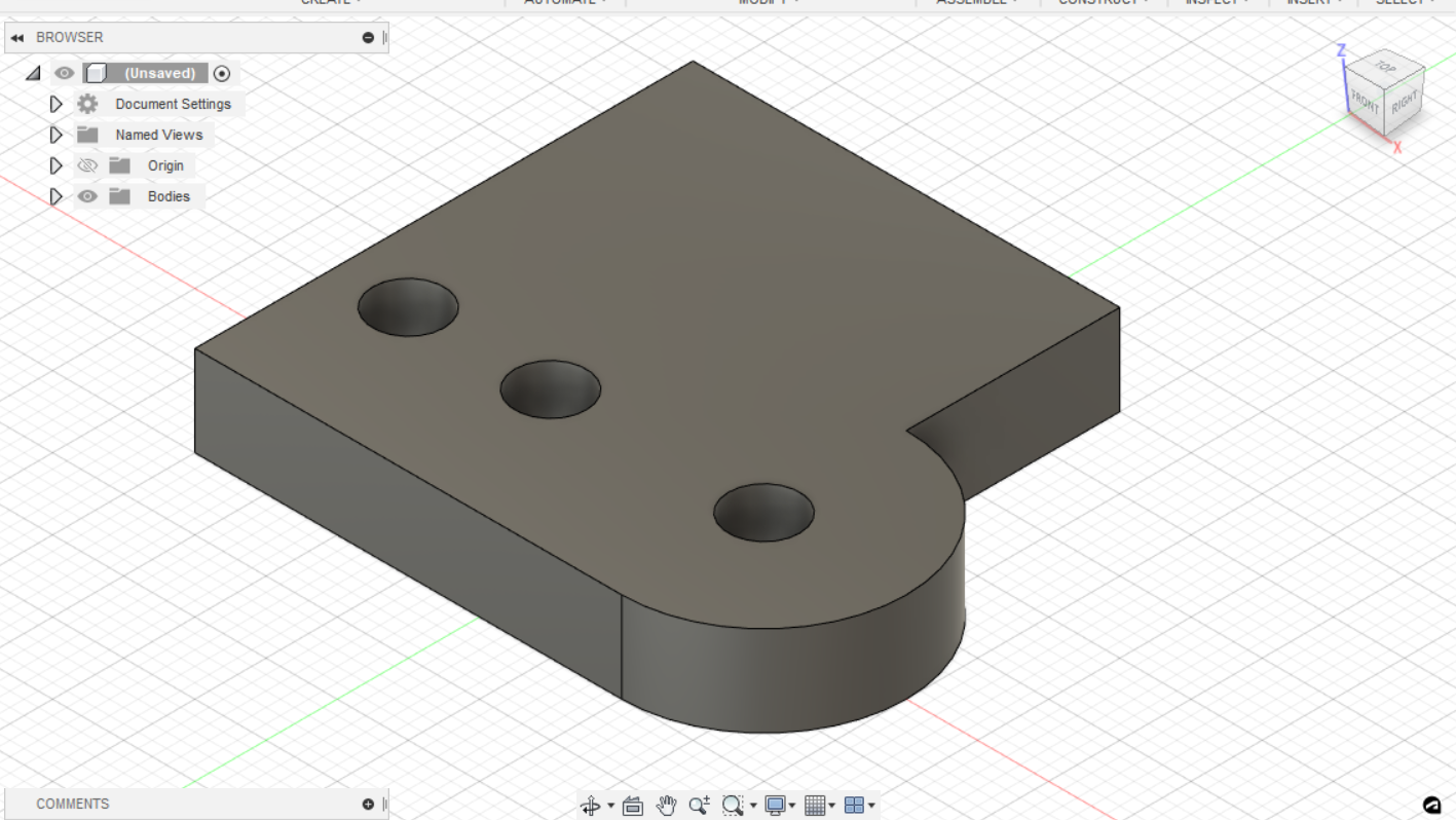
This part is the x-axis nema 17 holder - & it's level up the fram on the plywood
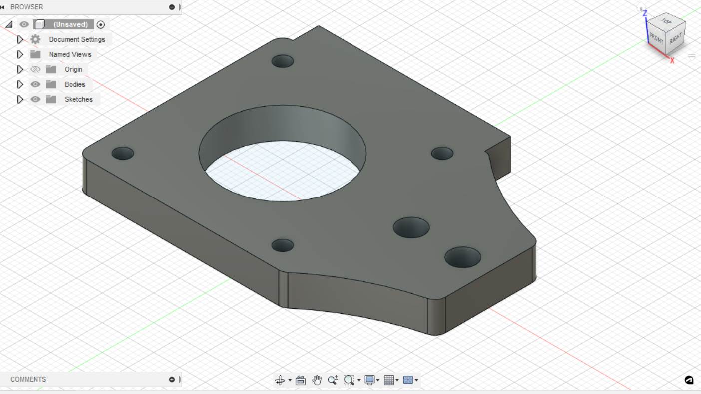
This part is the y-axis carriage - & magnet holder
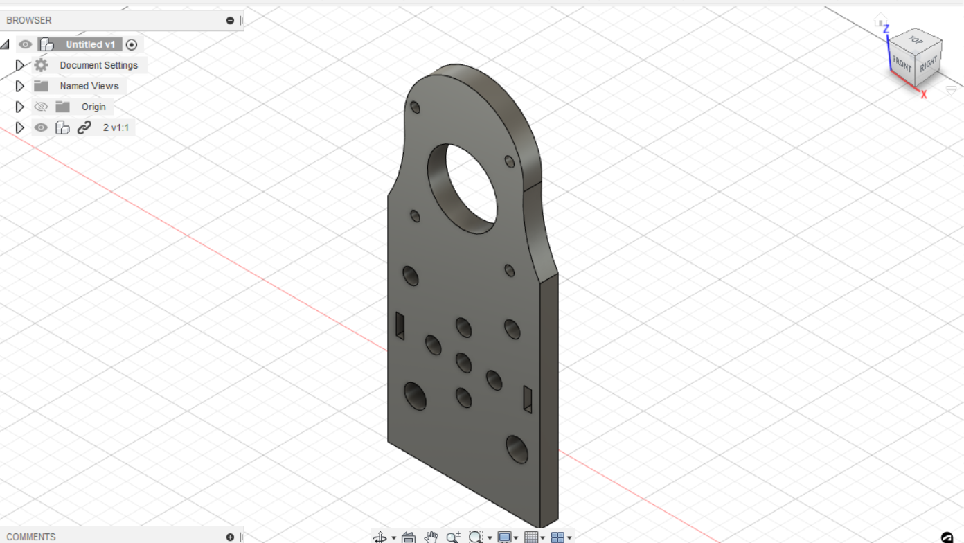
This part is the x-axis carriage
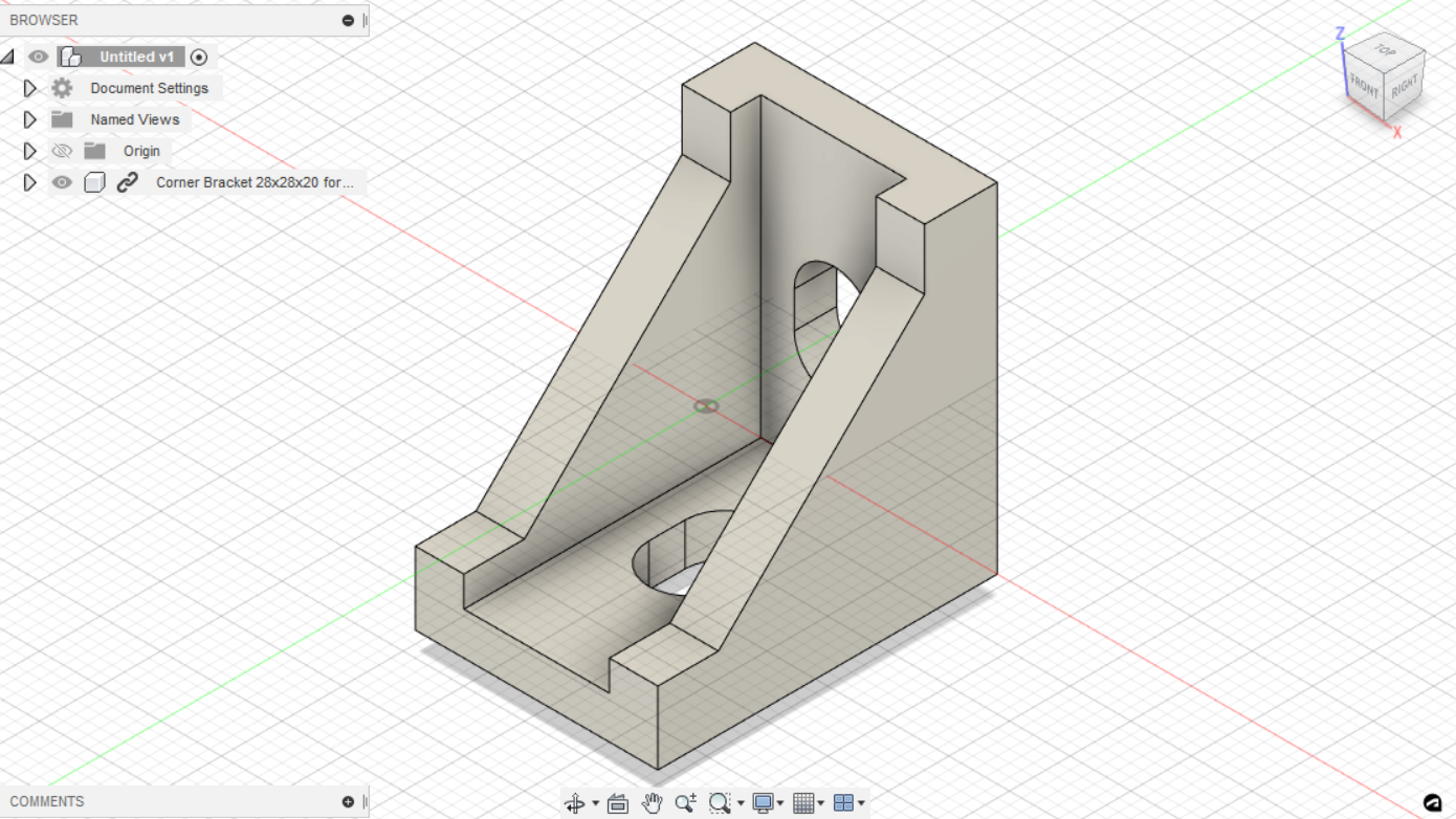
3D printed parts:
We used this part to secure the machine frame to the plywood
Now we are ready for assembly
step 2: assembly
The second step is assembling the parts. We thought it was easy but apparently, it will be a bit complicated. We started to fall behind the plane thanks to some obstacles but we will manage to finish everything on time according to our estimation. When assembling the frame, we realized the assembly is wrong. we mistakenly put the horizontal part on top of the vertical one and this will make it impossible for us to put the other parts in the right place. Hence, we wasted an hour disassembling the frame and re-assembling it again. As you can see in the picture below.
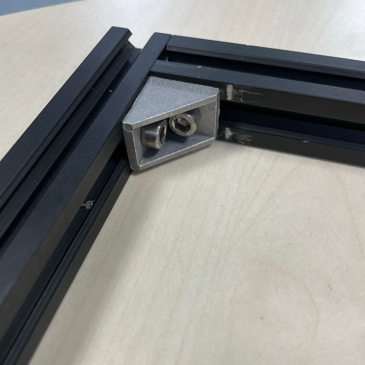
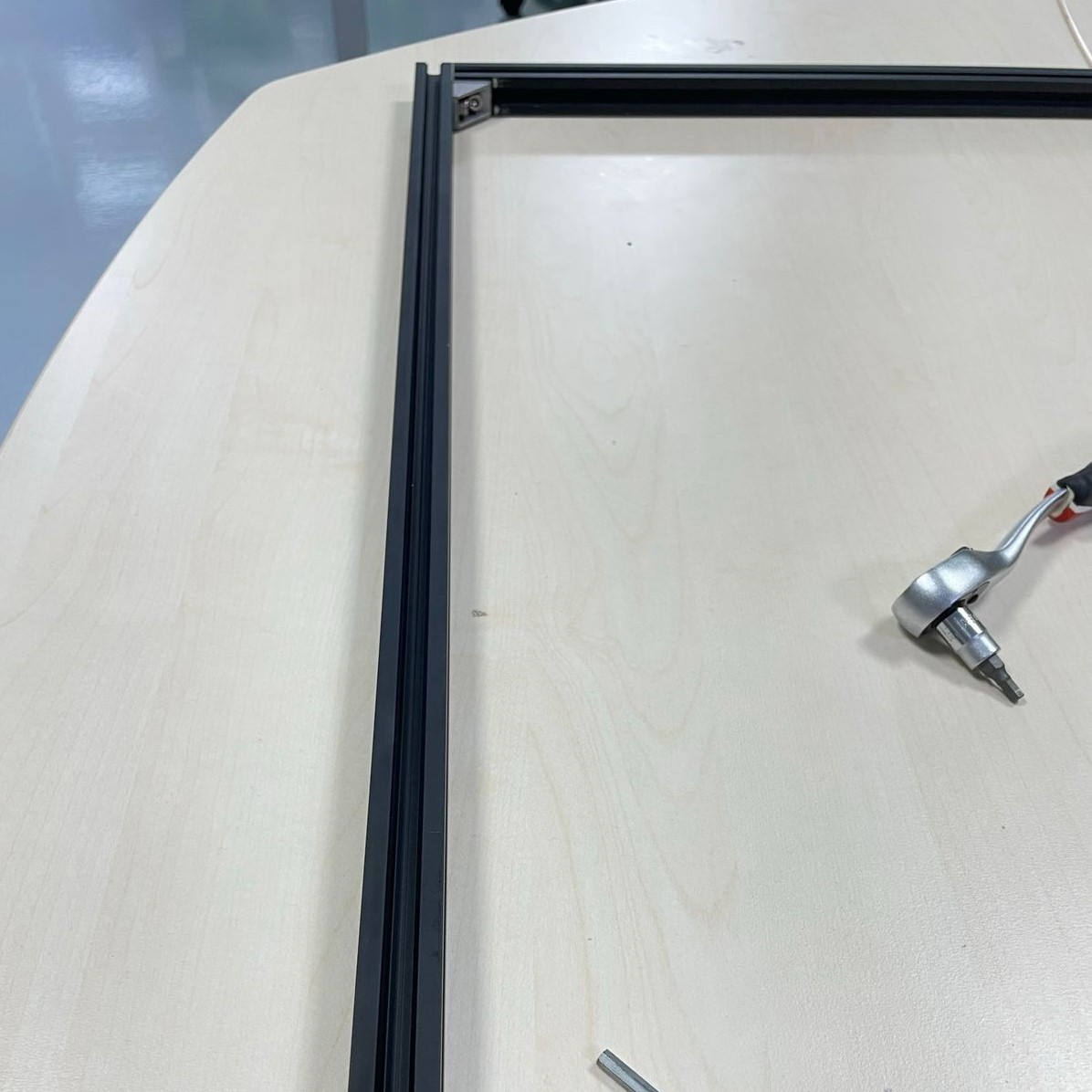
Also, we find out that we need to change the sizes of the nails for the design. Eventually, we succeed to assemble the profile as you can see below.
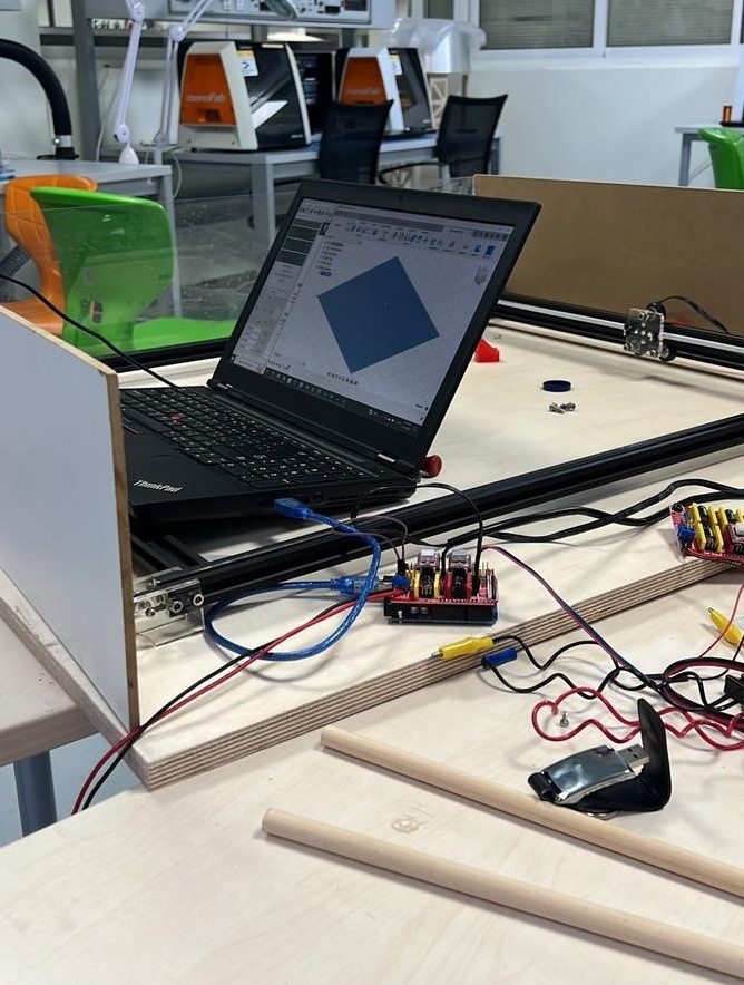
step 3: electronice & connection
The third step is electronic design and production.
Parts we used:
• Arduino UNO
The Arduino UNO serves as the brain of the system. It runs the control program and sends signals to the CNC Shield to control the stepper motors.
Connect the CNC Shield to the Arduino UNO using the appropriate pins.
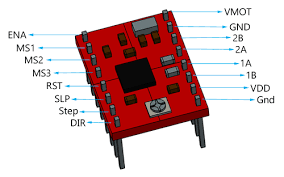
• CNC Shield Expansion Board with 2x A4988 Stepper Motor Driver For more detail's
he CNC Shield Expansion Board is a specialized board designed for controlling stepper motors in CNC (Computer Numerical Control) applications. It acts as an interface between the Arduino and the stepper motor drivers.
The A4988 Stepper Motor Drivers are used to control the stepper motors. In this case, three motors are employed, each connected to its own A4988 driver.
he A4988 drivers interpret the signals from the CNC Shield and control the movement of the stepper motors accordingly.
• Power supply
The CNC Shield and A4988 drivers require power to operate. Ensure the power supply voltage matches the specifications of the components which was 12v.
Connect the power supply to the CNC Shield to provide the necessary power for the motors.
• Copper Cables
Use copper cables to establish connections between the CNC Shield and the A4988 drivers. These cables transmit signals from the Arduino to the drivers.
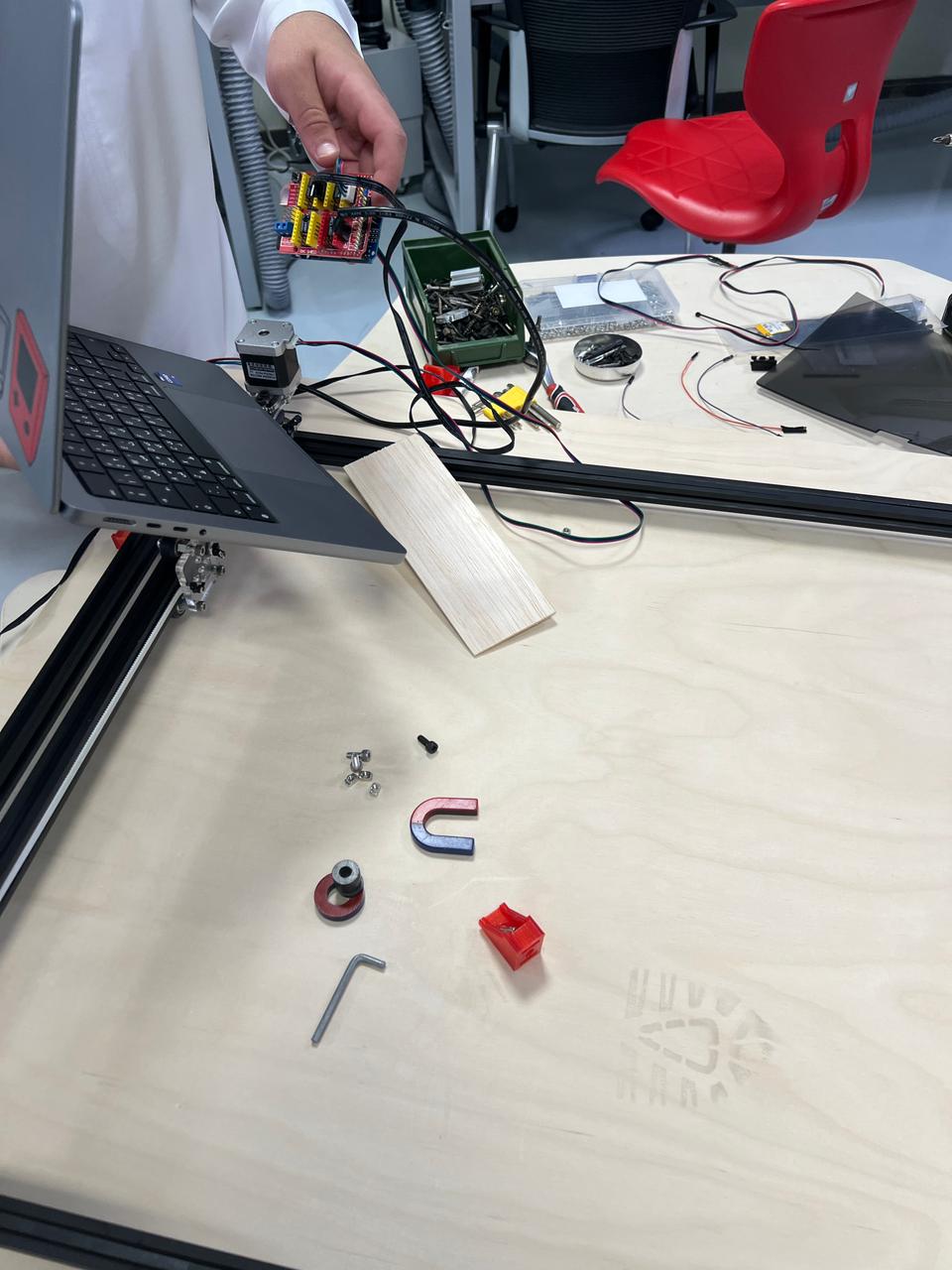
Abdulla took care of most of this part of the project. However, we discussed all the details of the project before starting production. We decided to go with three motors following the initial design.
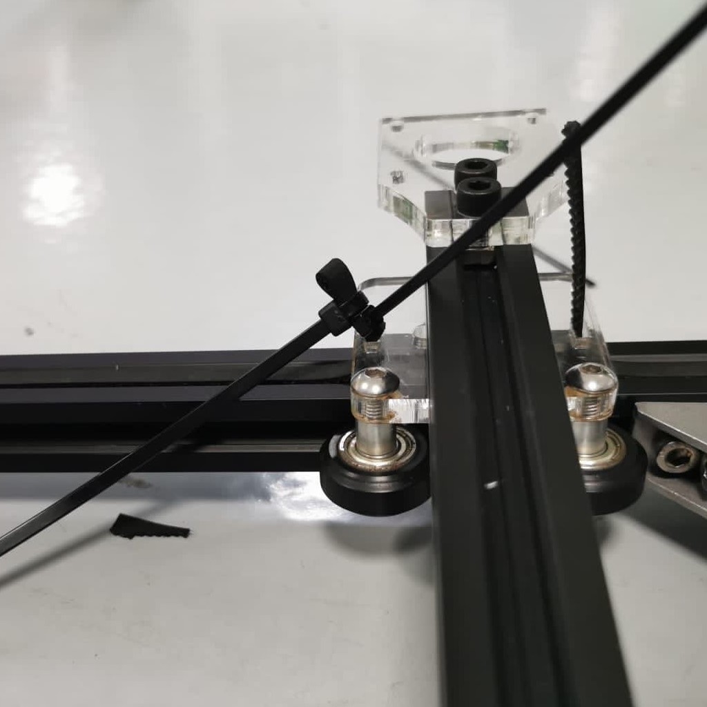
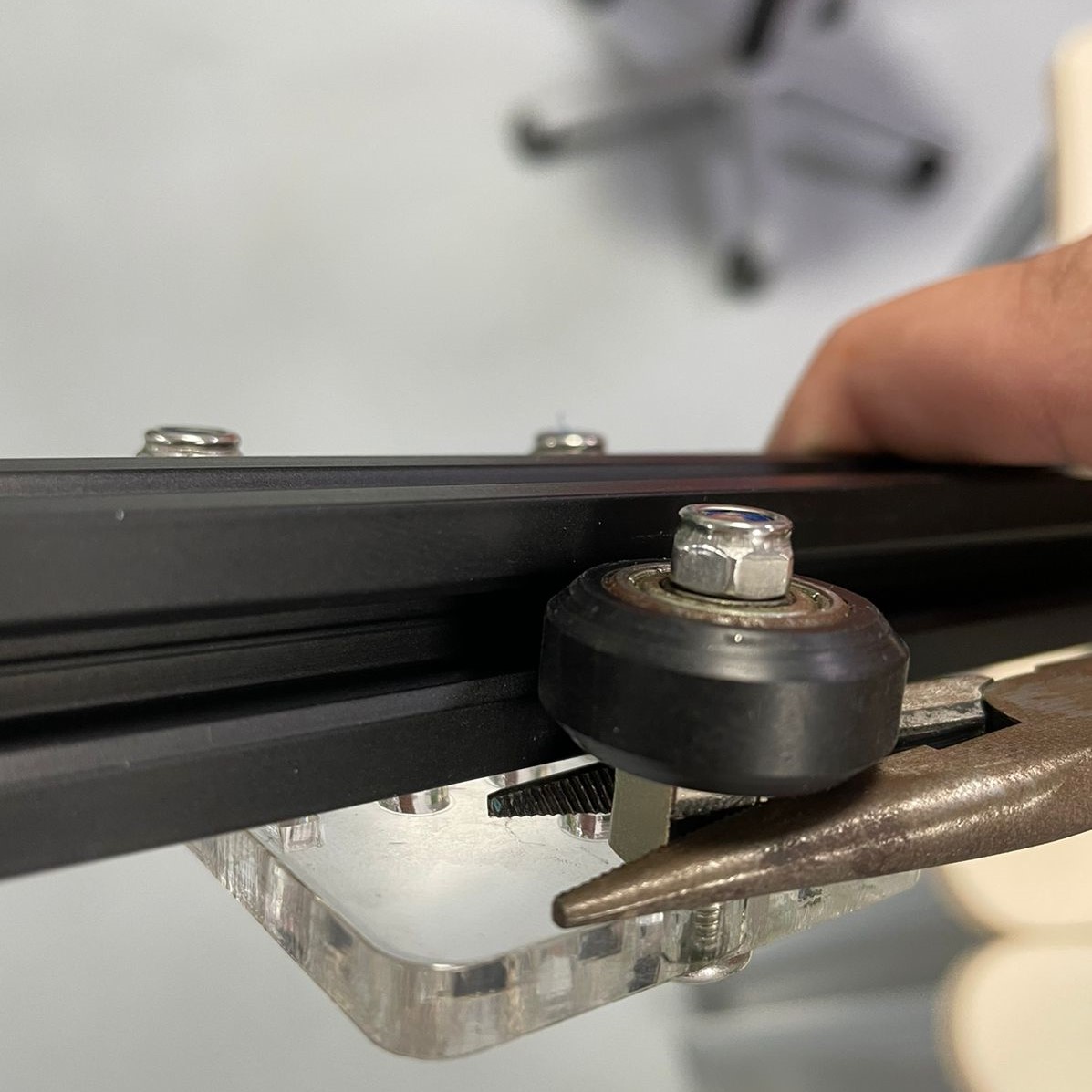
We used motors. They are small yet can successfully move the magnet. We connected the motors together using a simple pully system that we connect to the frame. We used Arduino to do the programming.
step 4
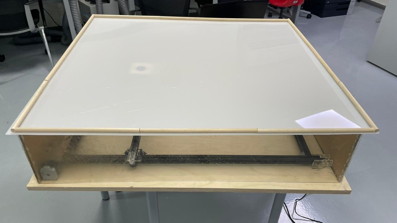
The fourth is cutting the table and placing the machine inside it.
Bashyer took care of this part but as we said earlier, we discuss almost everything in the project. We had to change the table dimensions several times. We tested the domain of the magnet which made us change the hight of the table a couple of times to make sure that it was fixed and it lies between the base and the roof which will hold the sand.
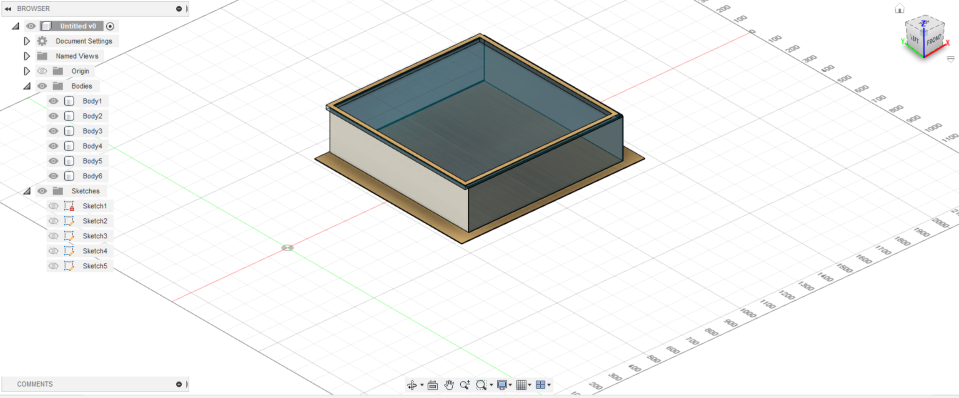
After finalizing the dimensions, we started cutting the parts of the table. First, we cut the base. We decided to go with a heavy piece of wood to guarantee that it will hold everything together and keep the machine stable while moving. The dimensions of the base are 95 cm*85cm. after getting the dxf. We started cutting.
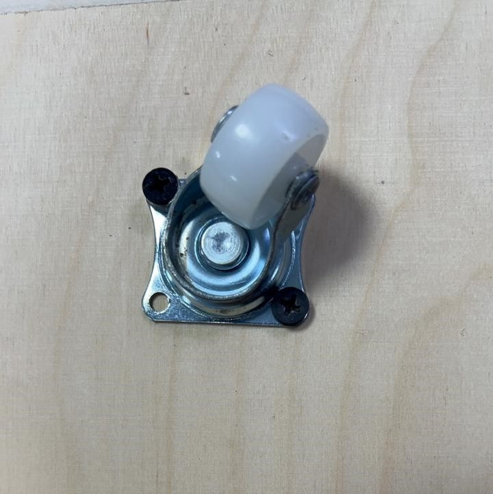
Also, we decided to add wheels to the base so we can move it easily. With the weight of the base, the frame and the sand it will be very hard to move the table. We thought that the wheels is the best solution for this problem.
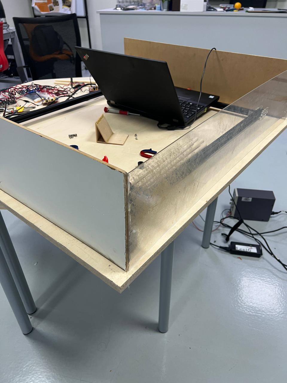
Then we started cutting the sides board. One of the sides of the wall is made of acrylic so we can see the motion of the machine while the other side is made out of white-coated wood. And the roof is made out of acrylic. It smothers than the wood. Hence, the friction force applied to the ball will be less. This will reduce the failure chances a lot.
step 5: Programming
Firmwares used:
• Arduino IDE Click To Download
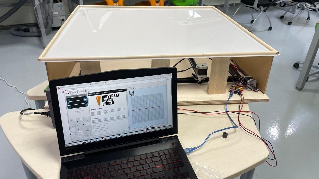
• Universal gcode sender Click To Download
• inkspace Click To Download
• 4xiDraw extention Click To Download
GRBL Configuration:
1- Download grbl-master.zip file and then follow these steps:
2- Open the grbl-master.zip file and extract the files.
3- Open the Arduino IDE, navigate to Sketch > Include Library > Add .ZIP Library…
4- Navigate to the extracted folder “grbl-master”, in there select the “grbl” folder and click the open file. Now we have to GRBL as an Arduino Library.
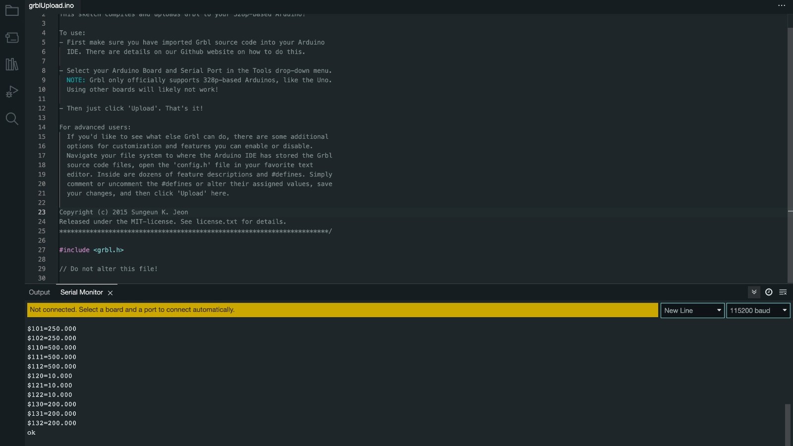
5- Next, navigate to File > Examples > grbl > grblUpload. A new sketch will open and we need to upload it to the Arduino board. The code might look weird as it’s just one lines, but not worries, everything happens in the background in the library. So, we just have to select the Arduino board, the COM port and hit that upload button and we are done.
At this point we should configure or adjust the GRBL to our machine. We can do that via the Serial Monitor of the Arduino IDE. Once we open the Serial Monitor we will get a message like “Grbl 1.1h [‘$’ for help]”. If you cannot see this message, make sure you change the baudrate to 115200. and Follow this page
        $100=250.000 (x, step/mm)
$101=250.000 (y, step/mm)
$102=3200.000 (z, step/mm)
$110=500.000 (x max rate, mm/min)
$111=500.000 (y max rate, mm/min)
$112=500.000 (z max rate, mm/min)
$120=10.000 (x accel, mm/sec^2)
$121=10.000 (y accel, mm/sec^2)
$122=10.000 (z accel, mm/sec^2)
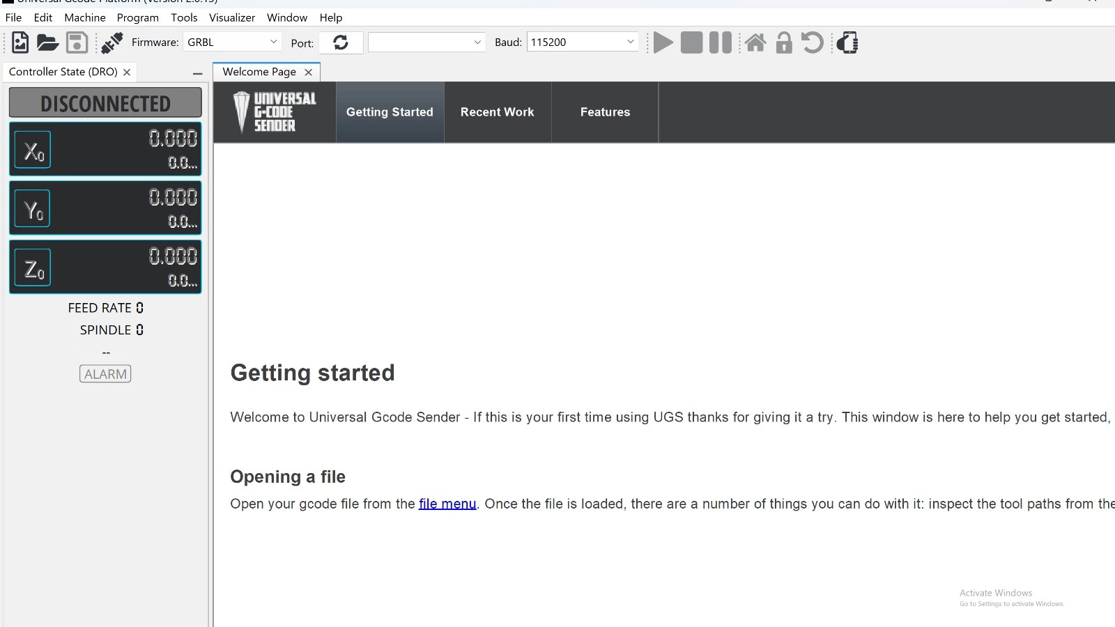
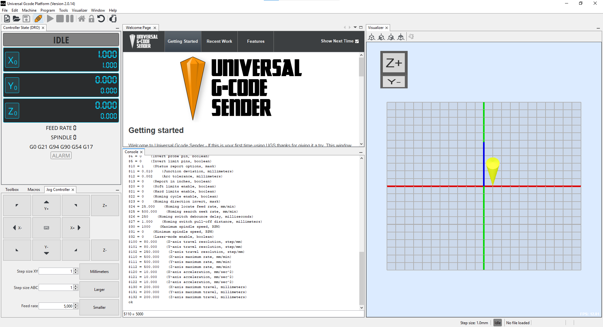
• Universal gcode sender
We made same changes in the setting as menshin in the below image.
• $$110 = 5000 (X-axis maximum rate, mm/min)
• $$111 = 5000 (Y-axis maximum rate, mm/min)
• $$25 = 500 (Homing search seek rate, mm/min)
• $$24 = 50 (Homing locate feed rate, mm/min)
• $$130 = 200 (X-axis maximum travel, millimeters)
• $$131 = 200 (Y-axis maximum travel, millimeters)
• $$120 = 50 (X-axis acceleration, mm/sec^2)
• $$121 = 50 (Y-axis acceleration, mm/sec^2)
- we set the correct Feed rate and speed from the consol
Finally, we can test the machine. We failed in the first and second trials but we finally made it.
Trial - 1:
Trial - 2:
Trial - 3:
This is how the machine eventually looked
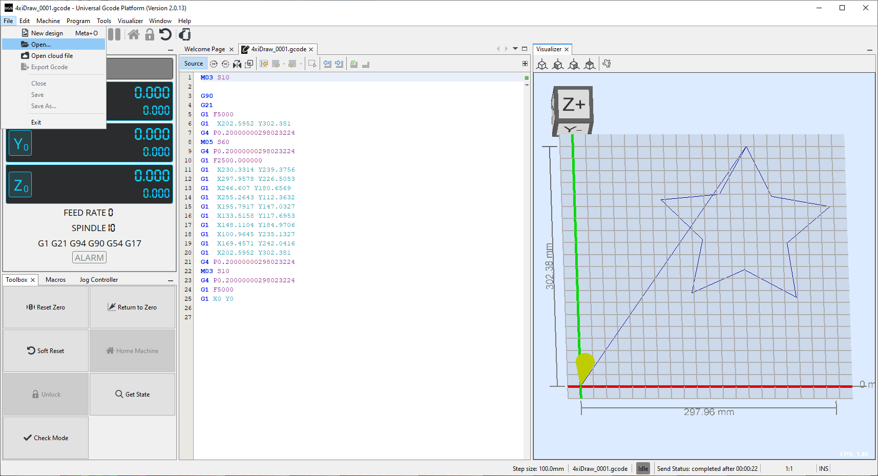
Steps 6: Gcode: Watch tutorial
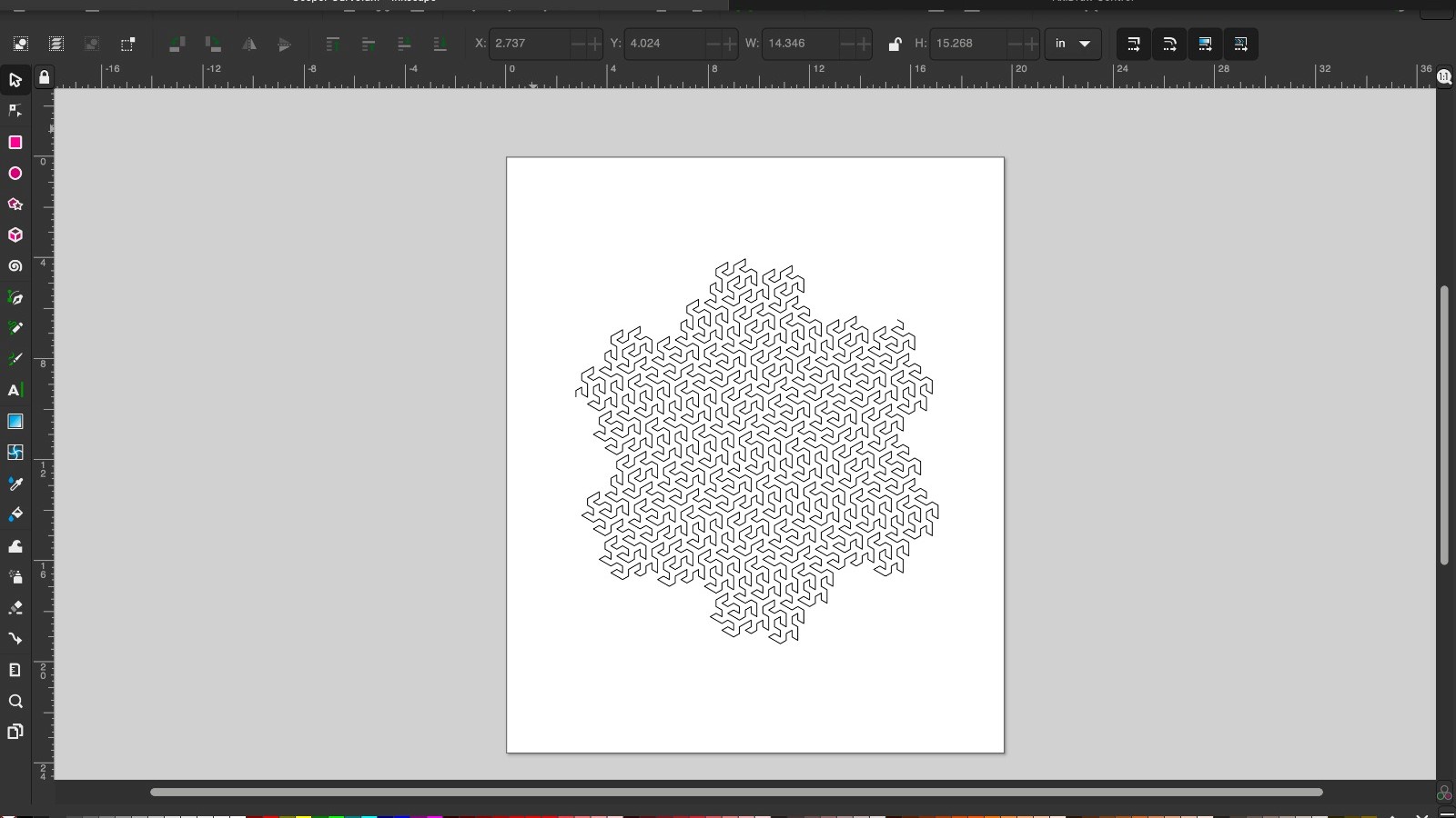
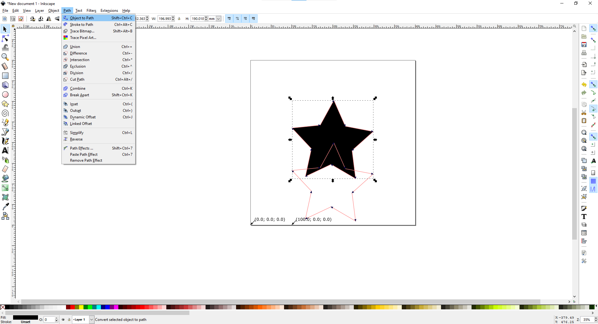
1- open the image you like and then click on (Path --> Object to Path)
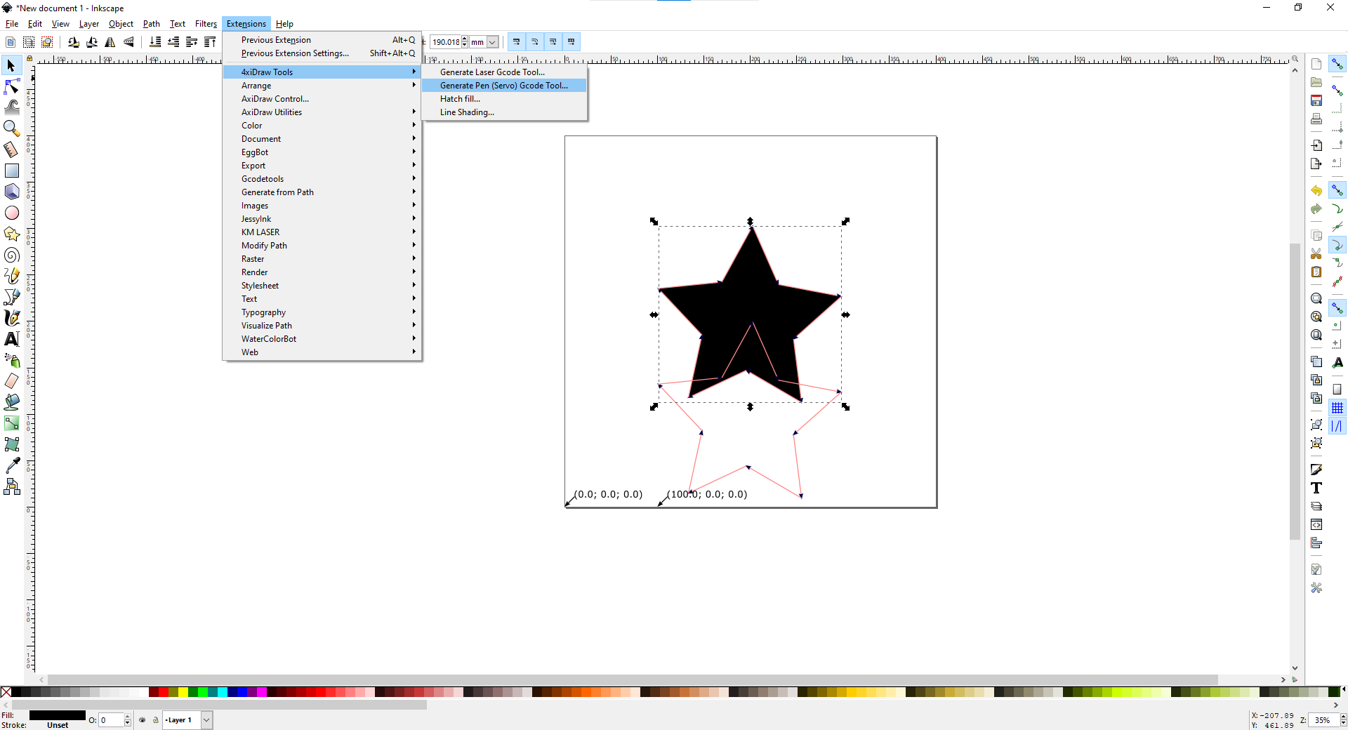
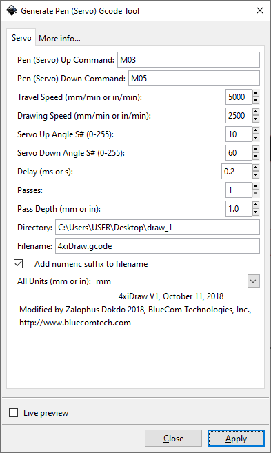
2- Then click on (Extentions --> 4xiDraw Tools --> Generate Pen) -----> For 4xiDraw Extention watch the tutorial Click Here
3- Click on (Apply)
4- Open the File and connect the machine and run it
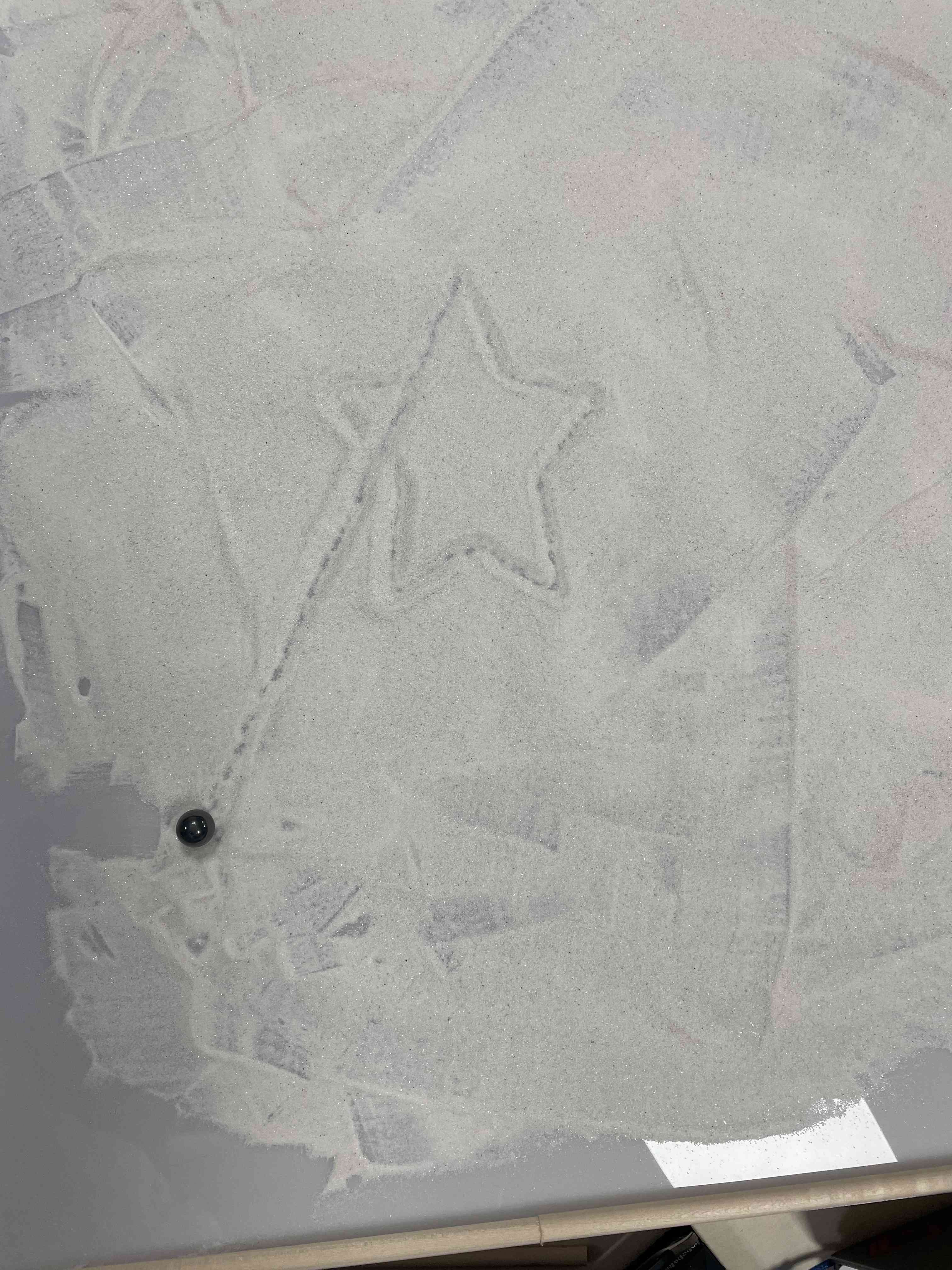
Stay toned for the final trial!
-------------------Here we go, Finally it's Done --------------------16/08/2023
Final Run:
1- Star