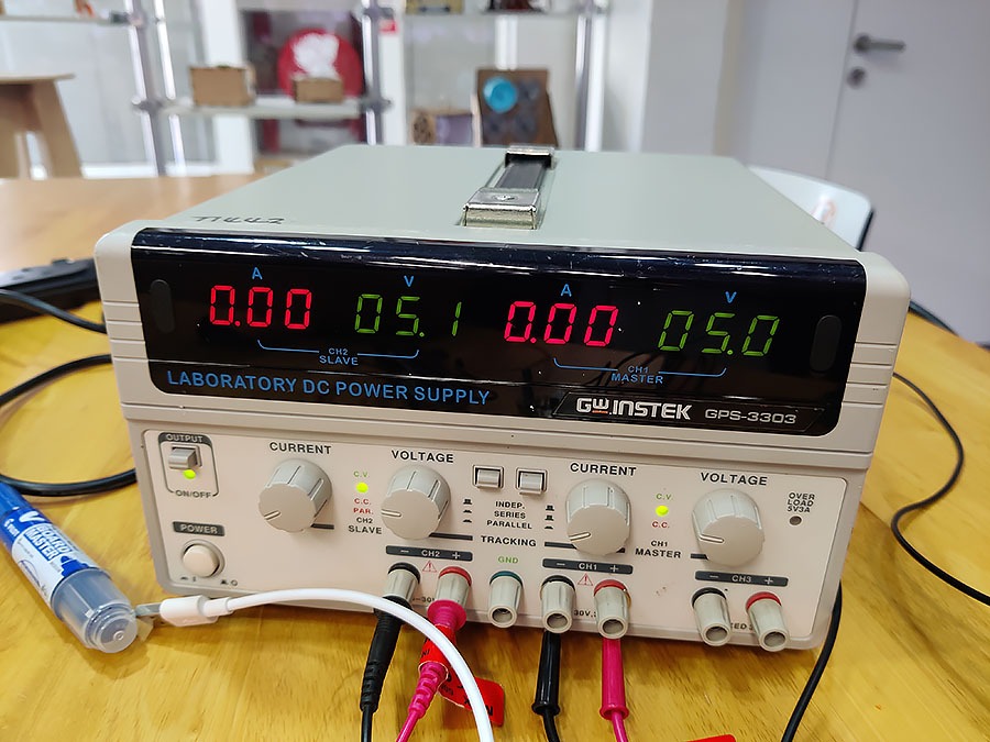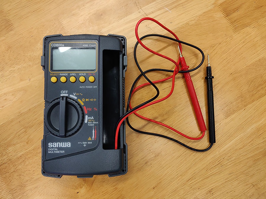

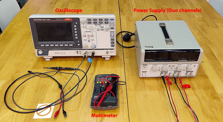
This week we should use and test equipment in our lab to observe the operation of a microcontroller circuit board (MCU). Our lab has a Multimeter, an Oscilloscope and a Power supply. We have measured the board and the output of it with these tools.
An "OSCILLOSCOPE" is an electronics test equipment that graphically displays signal voltage changes and makes it easier to see any problems occurring in an electronics circuit.
Engineers use oscilloscopes to study the changing process of various electrical phenomena for laboratory work. It can be used to capture, process, display and analyze the waveform and bandwidth of electronic signals.
Our Fablab oscilloscope is digital, it uses analog to digital converter (ADC) to convert the measured voltage into digital information.
The oscilloscope has a front panel with buttons and screen where we can either manually or in automatic mode search and measure the waves and see the form of them, we can measure its height (voltage) and width (time), this is a two dimensional graph that has a X-axis and Y-axis. The
More in how to use an "Oscilloscope" HERE.
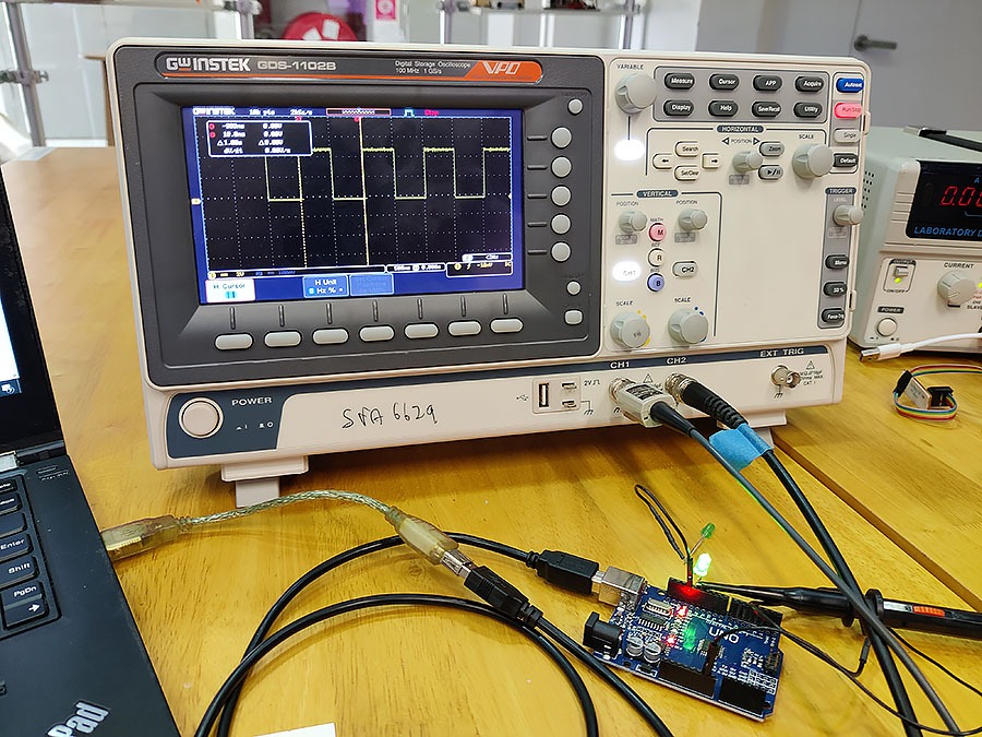
We wanted a LED light to turn on and off with delays of 500ms in a loop code
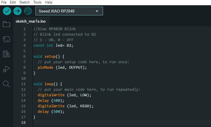
We wanted to see the difference on the signal waves between two Microcontrollers, an Arduino Uno and a XIAO RP4020. Both Microcontrollers were loaded with the same BLINK CODE
We started the measure touching the light with a "pen Probe" with its sharp tip, this Probe brings the signal to the oscilloscope. We put a transistor in to the circuit to prevent the voltage drop in the reading in the case of he Arduino Uno Microcontroller as it was connected to an input of 5V.
|
|
|
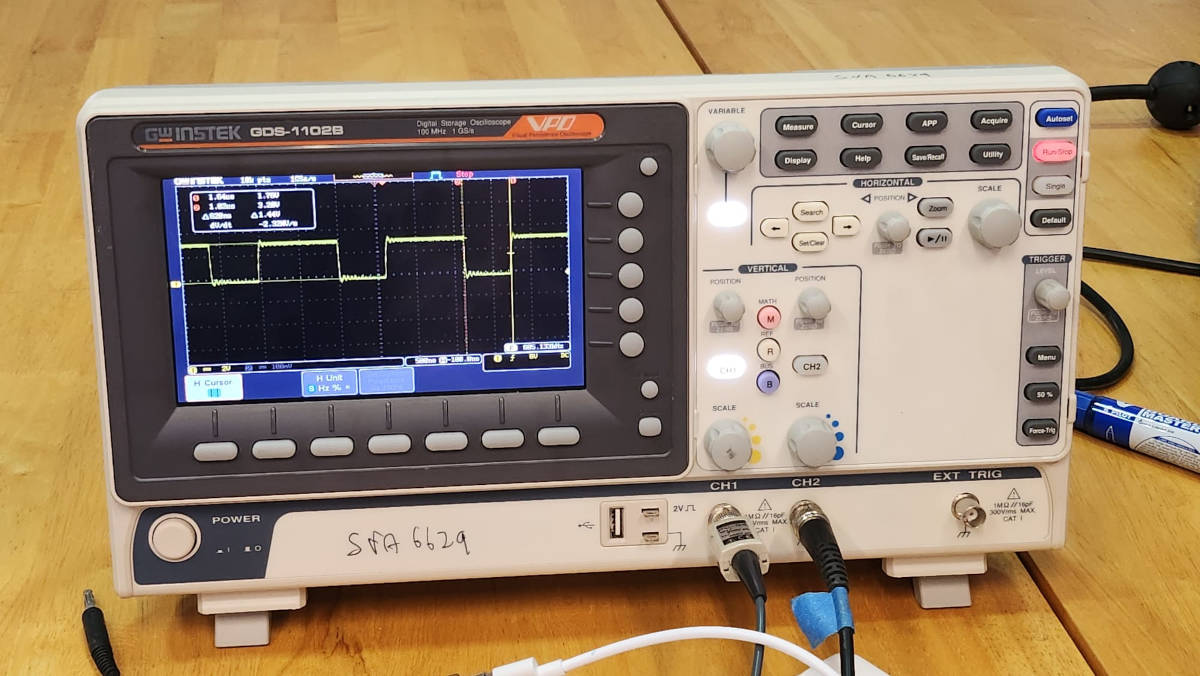
Both of the waves were quite acurate in terms of the Code and connections, giving 3volts on voltagein the case of the XIAO 4020 and 5volts in the case of the Arduino Uno, the time of the waves was pretty accurate each positive and negative (ON-OFF) each 500ms.
But then we wanted to see if we could measure a real difference in the internal clock of the Microcontrollers (Speed) as the XIAO 4020 has a speed of 133 MHZ and the Arduino Uno 16 MHZ, the first one being much faster than the second one.
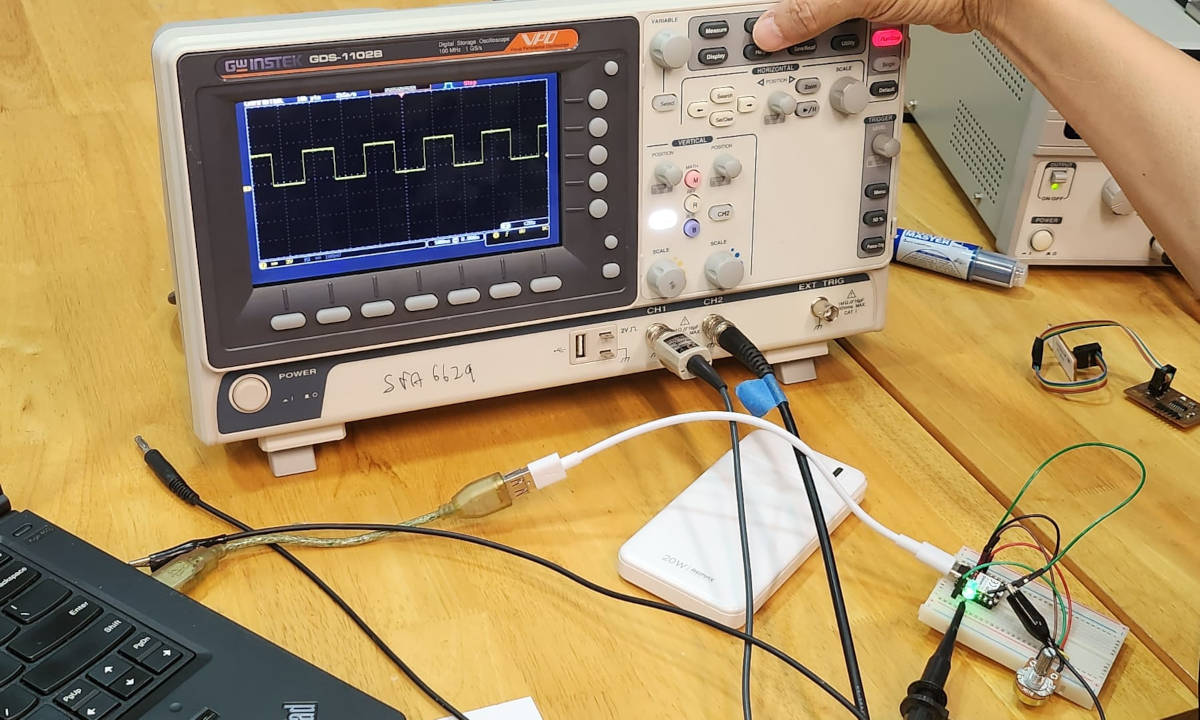
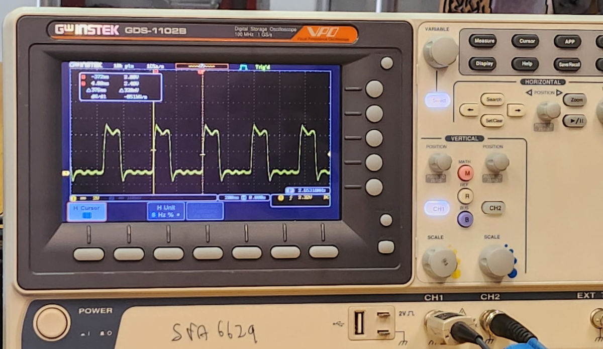
A way to measure the internal clock, was changing the code of BLINK with NO delay, so the loop will "turn on-off" with not delay, in our eyes the light will appear ON all the time but in terms of code there still and ON-OFF loop, that means there are waves of micro seconds that can be measured. This waves tell us the speed the Microcontroller takes to do each loop meaning the speed of the internal clock.
|
|
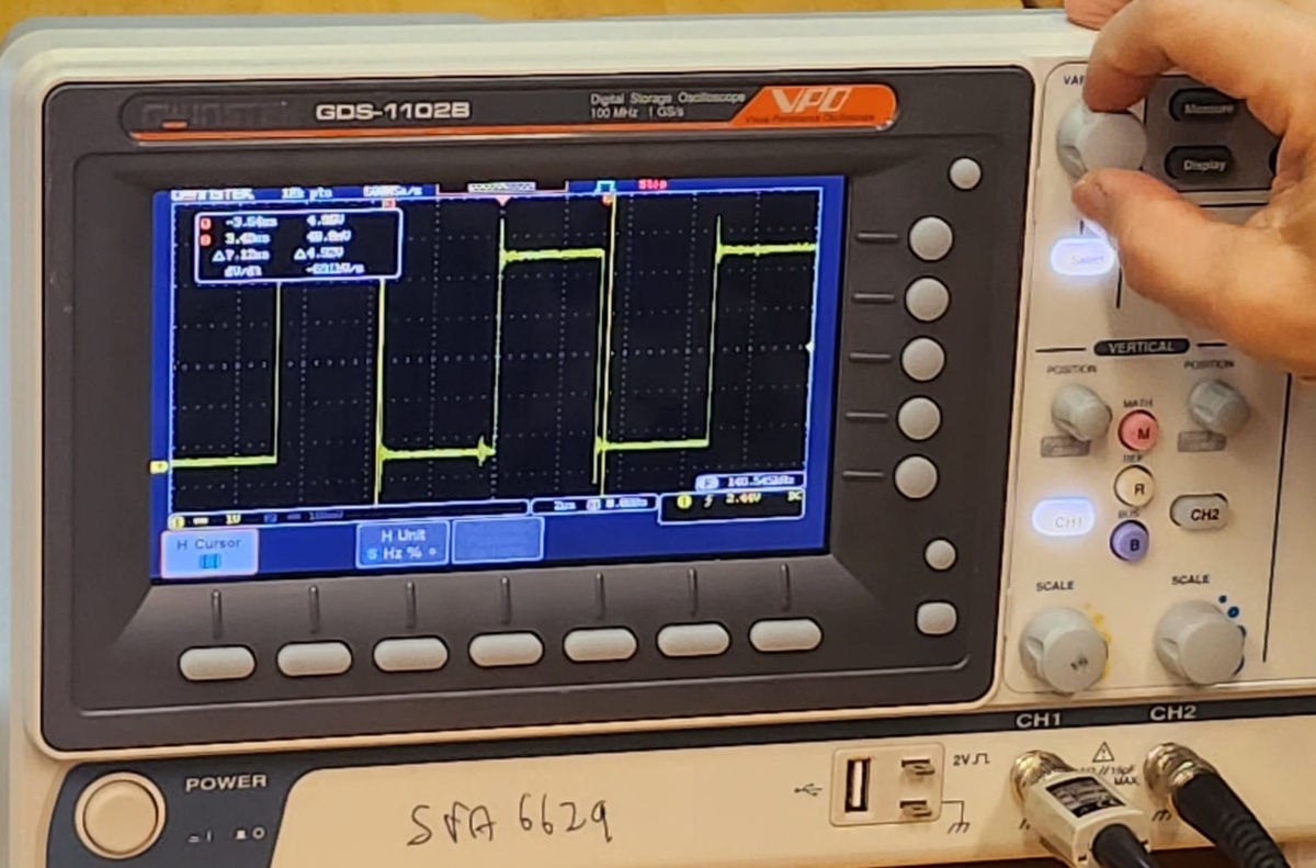
in the case of the XIAO 4020 Microcontroller we could see that it took almost double the time to start when the loop was finish giving an ON mode double the time of OFF mode, this is the time the internal clock takes between loops, The Arduino Uno didnt show a big difference in terms of timing, but there was a difference.
We can say that the Arduino takes shorter delay in the loop, but what is happening is the internal clock of the XIAO is much faster so it can show in more detail the delays, one is 16 MHZ speed and the other 133 MHZ .
This problem to human eye is not "important", which means if we have a code for an action that can have a delay of microseconds, like moving a curtain, it is not a mayor problem.
But when we use this microcontrollers in equipment like in medical equipment or cars where the response has to be accurate and "on the clock" this type of delay could be a problem and a danger sometimes.
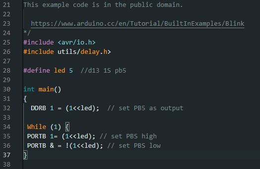
We could solve this with a new CODE in GCC Programming to avoid loosing time in the loop, this is called "bared metal programming", to do so, we have to go to the data sheet of the Microcontroller and find the way to program the internal clock directly. When we change the coding the loop gets much faster, the time could be measured in nanoseconds, we could see the wave is not very stable as the change between ON and OFF is very fast that it doesn't have time to stabilize. Below we did the Bared metal programming for the Arduino Uno Microcontroller.
|
|