WEEK10. Mechanical Design
This week was quite hard, struggling with machine design, to be precise with my colleague Christophe we designed a a two axis plotter. This machine can draw on different kinds of supports using a pen or a felt-tip pen.
We took inspiration from a project present online and on Thingiverse.
Group Assignments
- Design a machine that includes mechanism + actuation + automation + application
- build the mechanical parts and operate it manually
- document the group project and your individual contribution
Sketching
First of all we start sketching the machine and to go deeper in its functioning.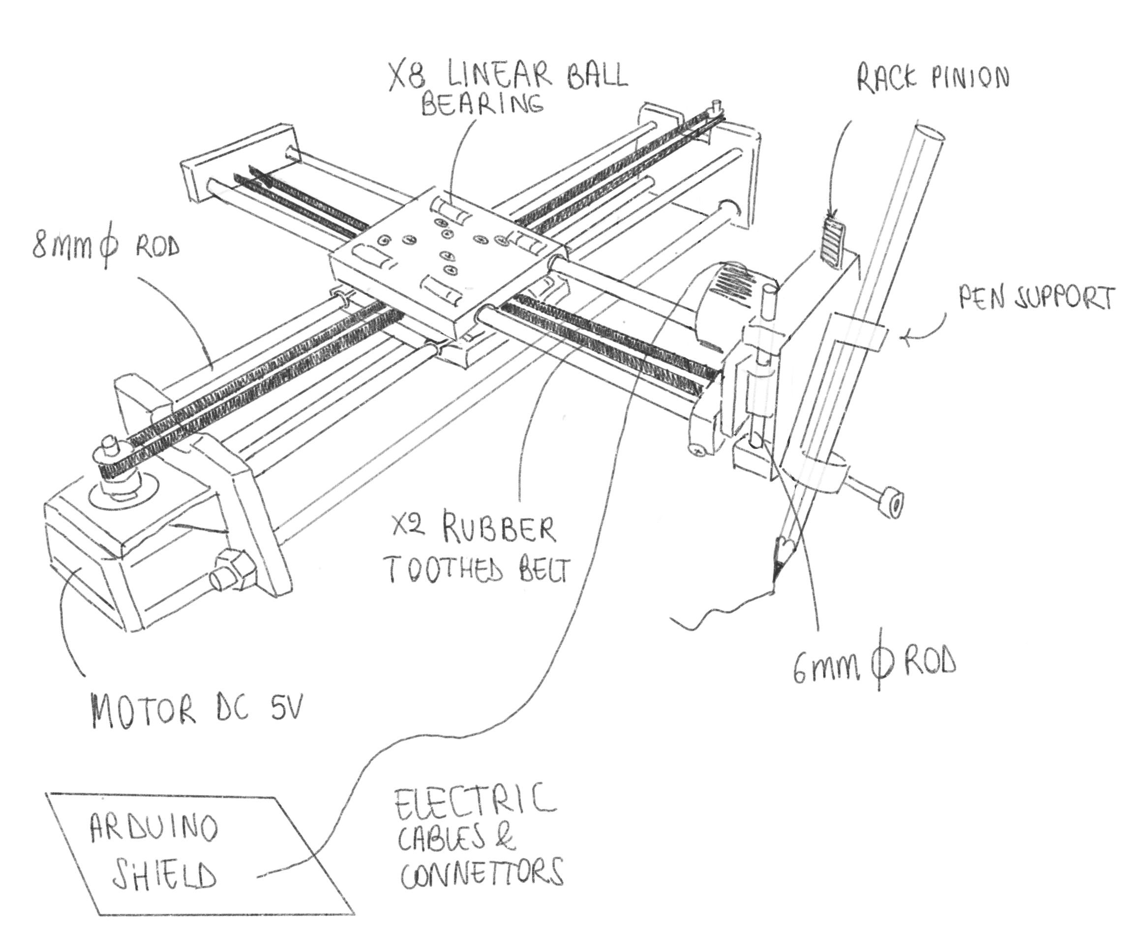
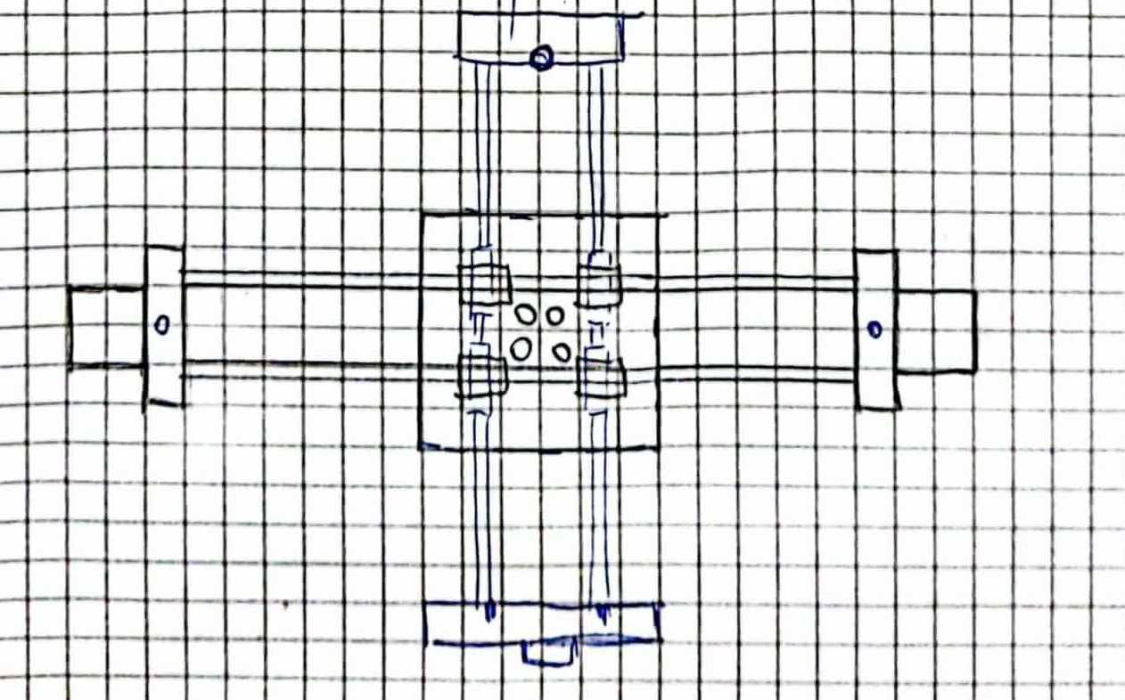
The machine has two motors on the X axis and only one toothed belt, arranged as in the picture below (each color represents one of the four possibile configurations of the machine).
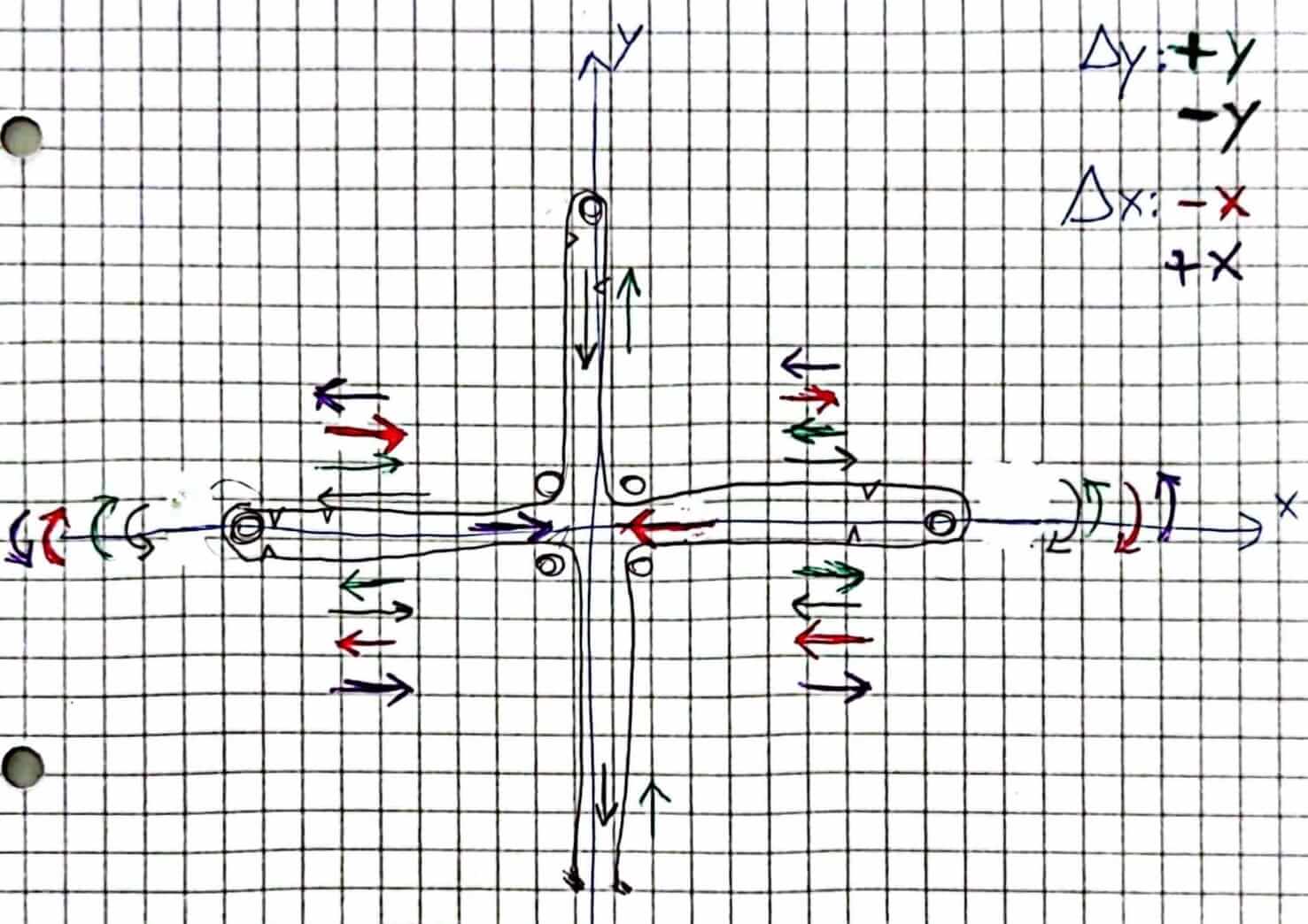
The general rules for the motion of the pen are:
- The two motors that rotate in the same direction: gnerate a motion on the X axis
- The two motors that rotate in the opposite direction: gnerate a motion on the Y axis
- The two motors rotate in the same direction, in clock-wise direction generate a motion of the X axis to the West.
- The two motors rotate in the same direction: in counterclock-wise direction, generates a motion to the Est.
- The two motors rotate in the opposite direction, the West motor in clock wise direction and the Est motor in counterclock-wise direction, generate a motion to the North.
- The two motors rotate in the opposite direction: the West motor in counterclock-wise direction and the East motor in clock-wise direction, generate a motion to the South.
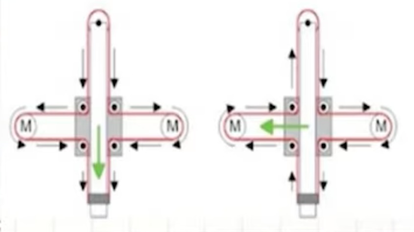
About the workflow and conversion in .gcode of the file, it is similar to the coreXY method.
3D Modelling
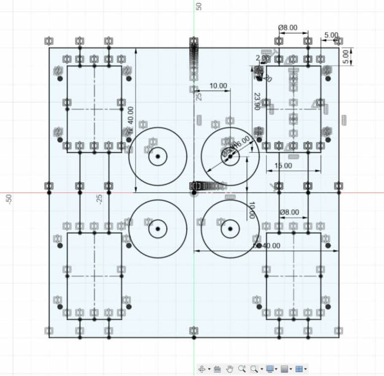
Me and Christophe splitted the work in two part, I worked on the 3D modelling part. I modelled the plotter components in Fusion 360. I started importing the chosen components in the working project space. These components are fundamental for the measure and for the final assembly process.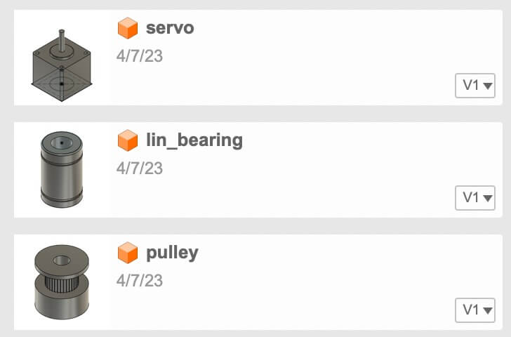
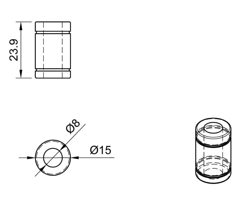
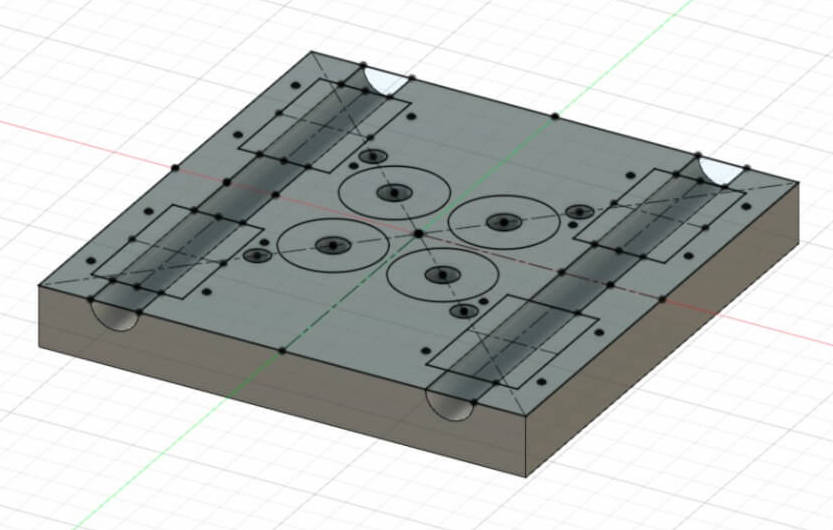
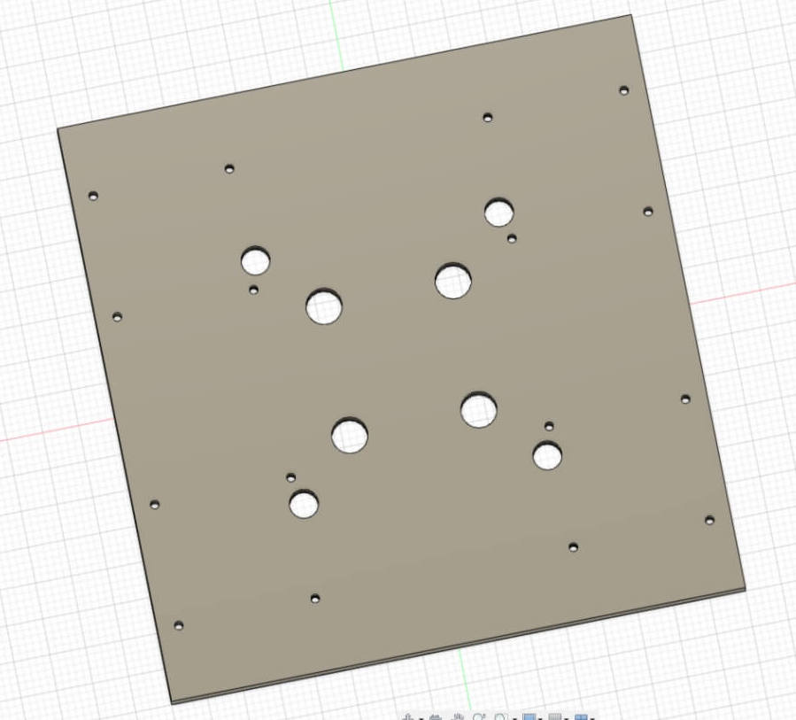
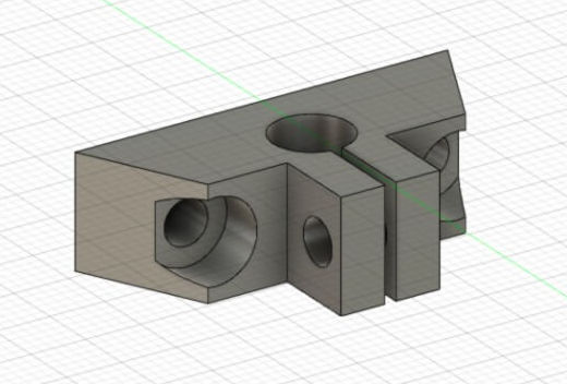
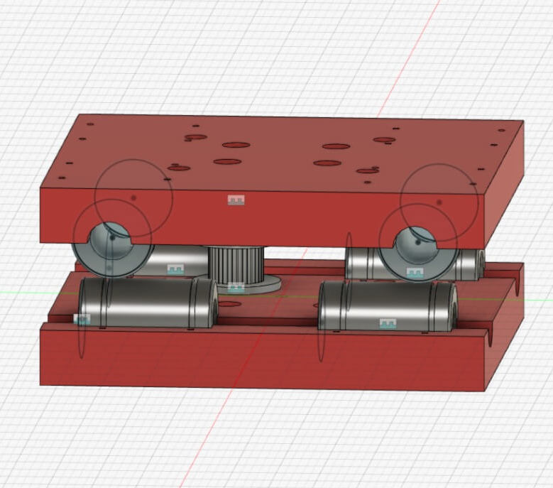
The "nozzle" component
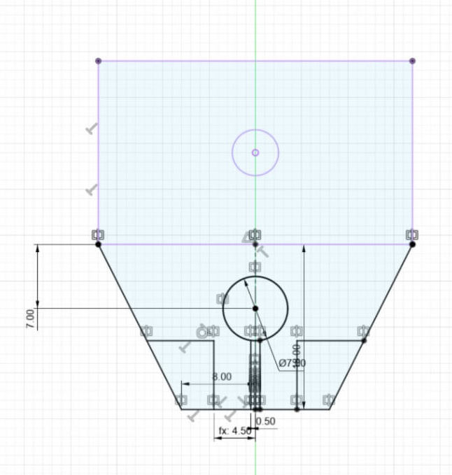
I started modelling the core component, the nozzle.
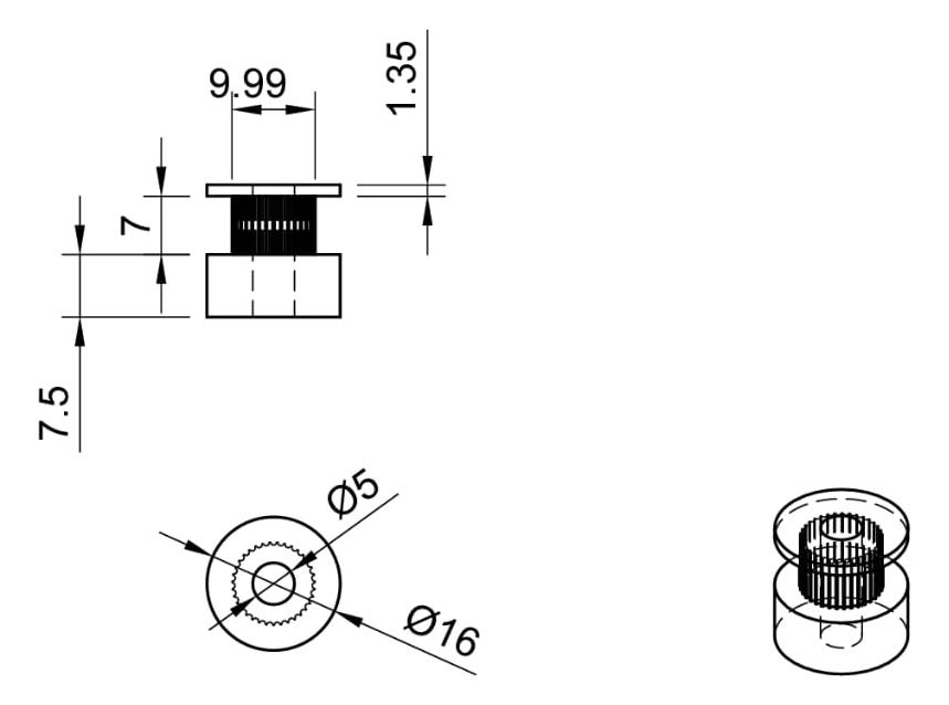
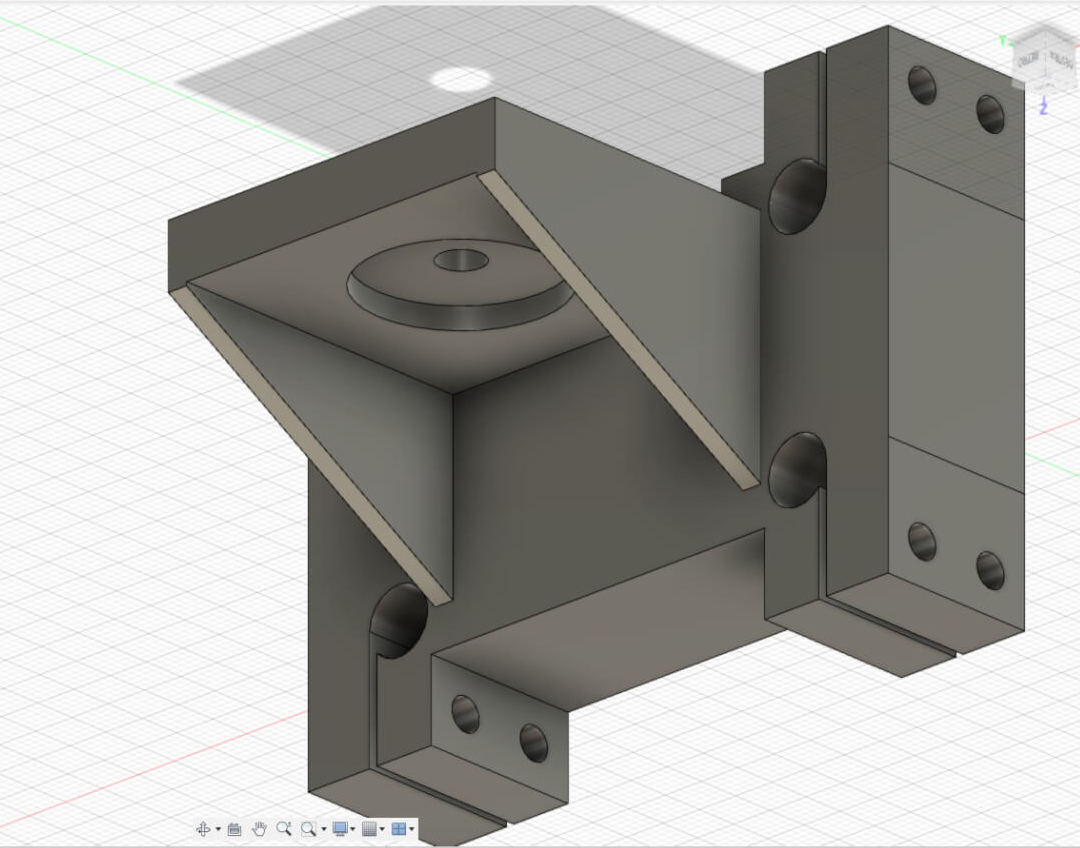
The other component
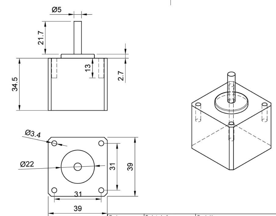
The north components
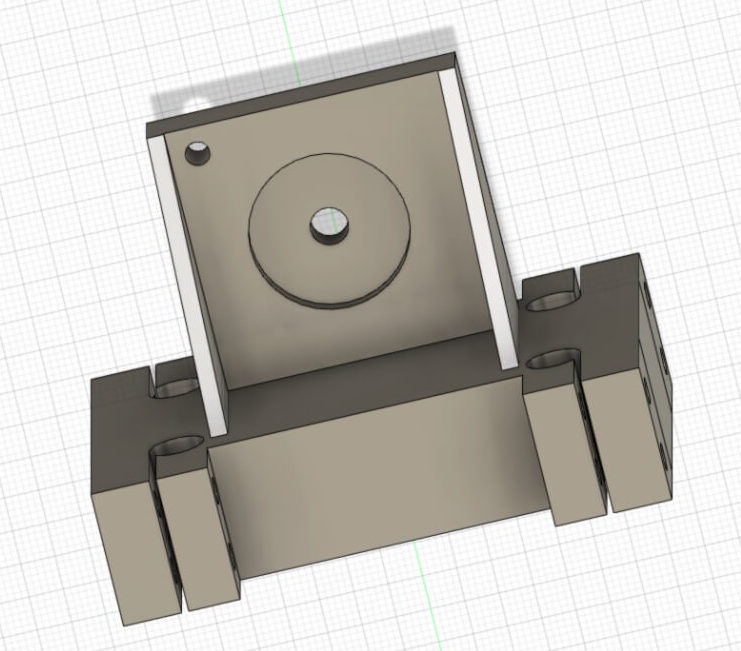
The south components
For the pen support we decided to model a pice that can be removed and replace with an other piece with also the z axis, in order to have the future possibility add a rack pinion to detach the pen from the paper. Moreover, you might change the dimensions of the actuator.
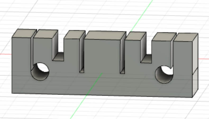
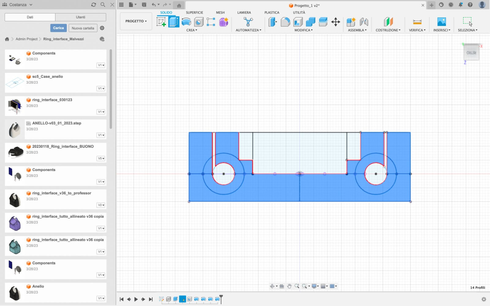
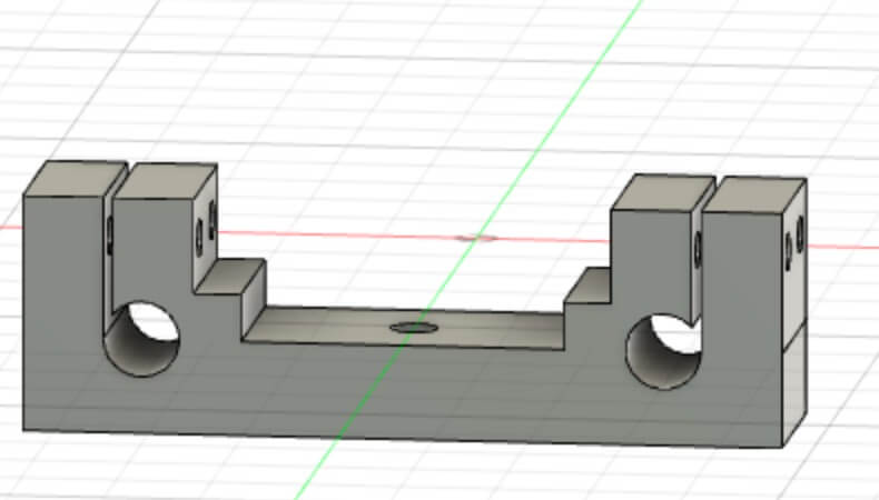
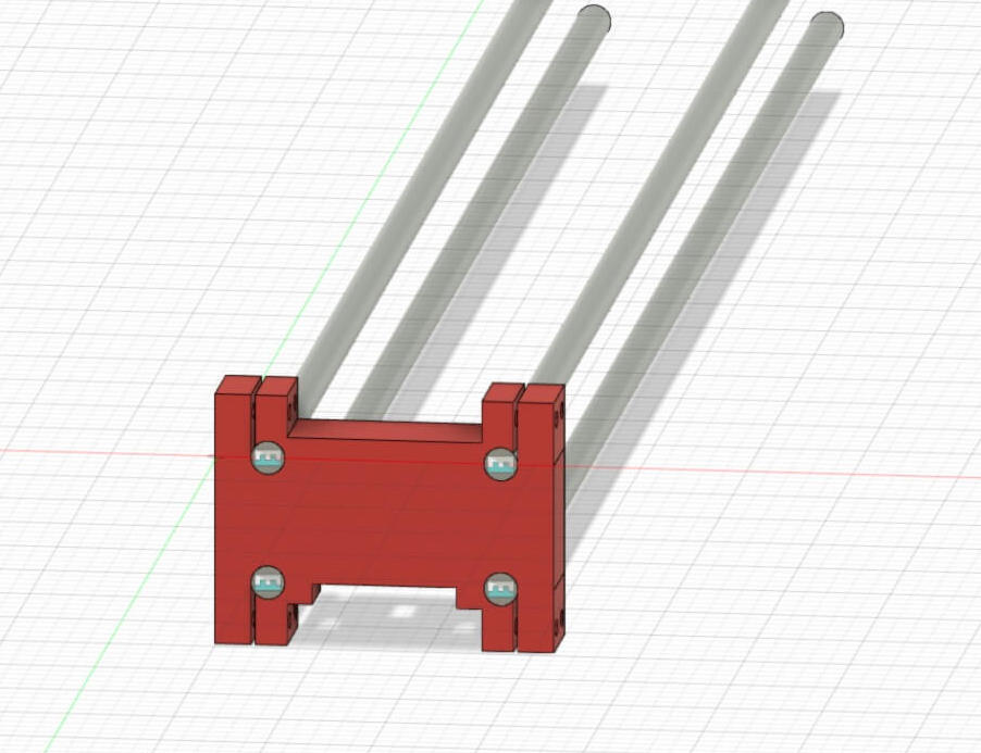
Then I modelled the cover for the servomotors, to make the structure more resistent. The holes for the rod have a cut to make them quite flexible in the insertion of the rod.
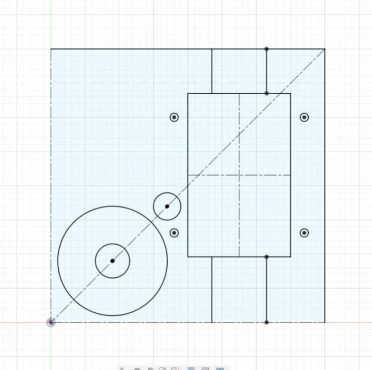
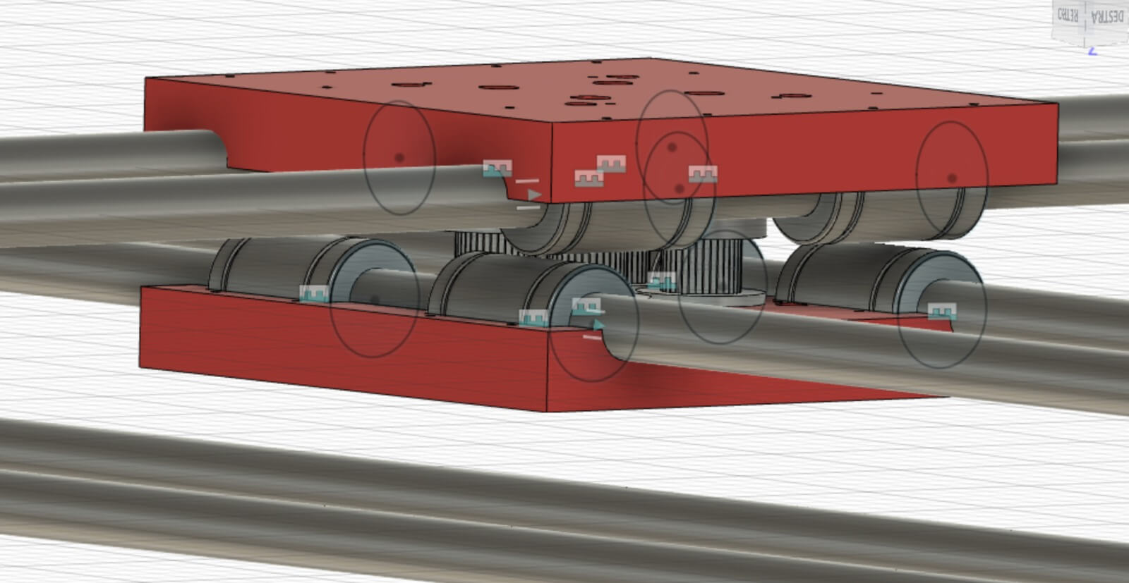
Assembly process
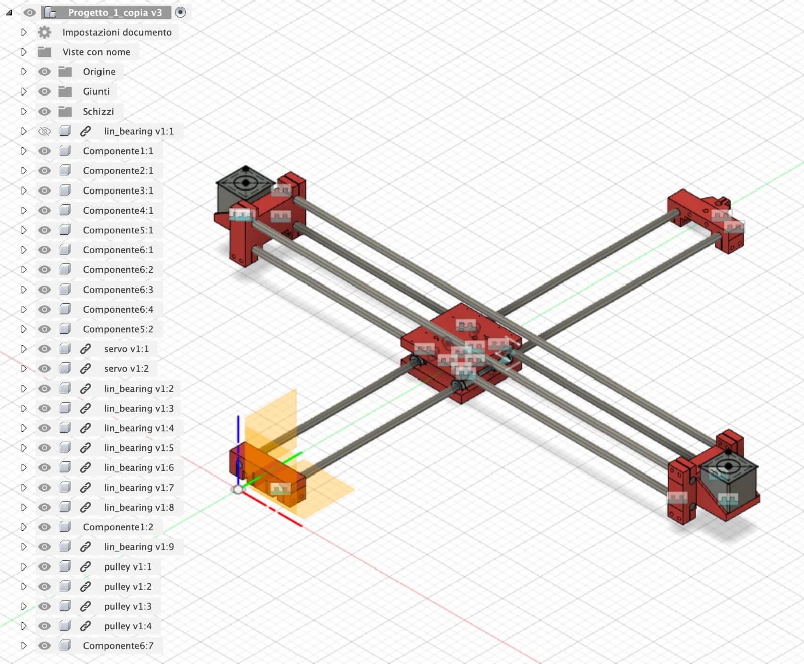
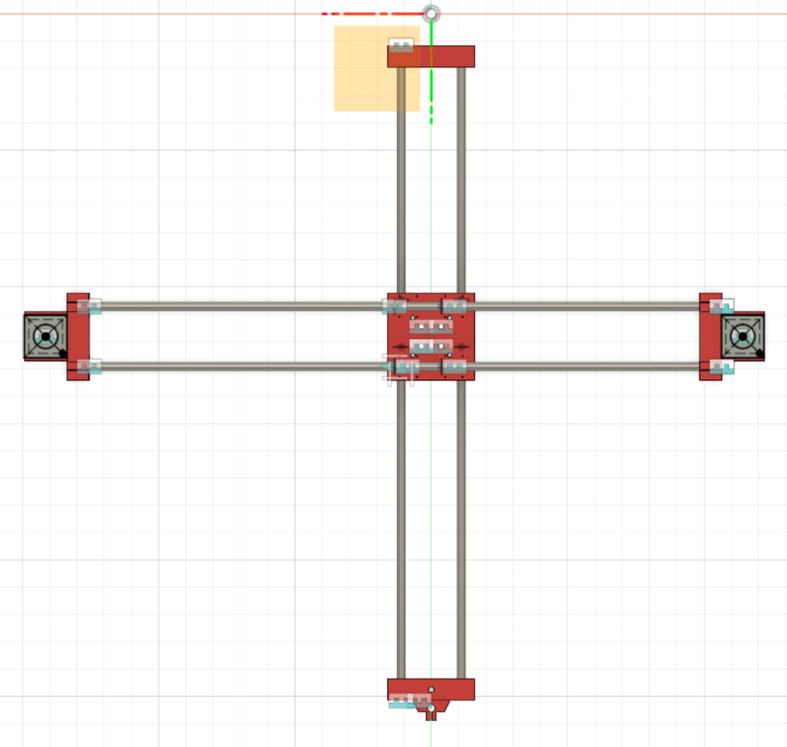
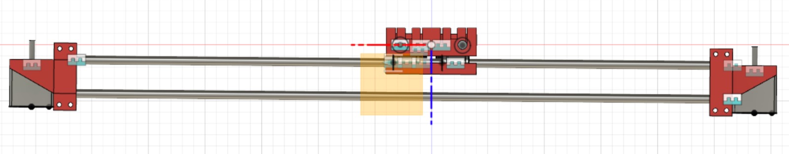
Using the assembly tools in Fusion 360, I assebled the components previously modelled. Paying attention to the intesection.
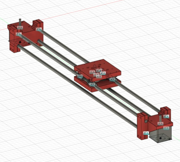
Here there is the machine fully assembled.