WEEK09. Output devices
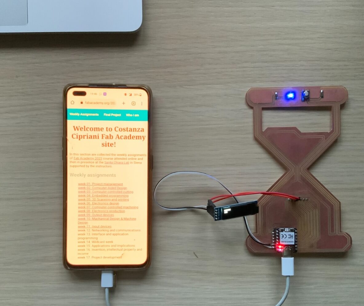
This week I programmed my glass hour PCB to run tomato timer cycles of work and pause, in order to efficient my working cycles time.
Assignments
- individual assignment: add an output device to a microcontroller board you've designed, and program it to do something
- group assignment: measure the power consumption of an output device
Output devices chosen:Oled Display and leds
For this week as output devices I chose two led, one implemented on the PCB and one other is the RGB led present on the Seeeduino XIAO RP-2040.
Additionally, according with the requisites of my final project, I decided to implement a small Oled display. On the display it is shown the conuntdown of the tomato timer and some interface messages.
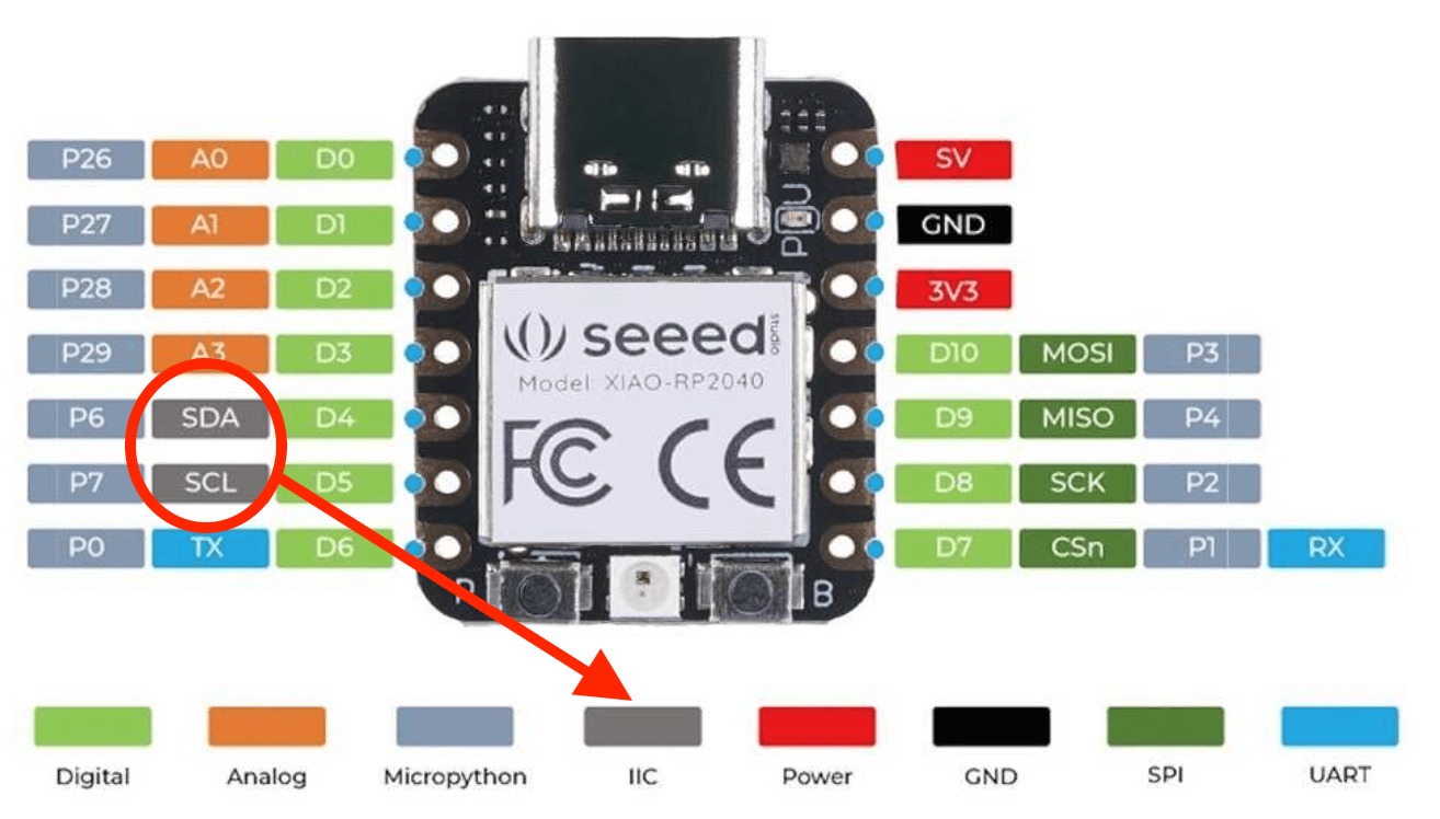
To connect the Oled display the apposite pin of the microcontroller XIAO-RP2040 must have the ICC protocol. If any pin has this protocol you have to create a new PCB with the output sensor and the IIC protocol.

Progamming the PCB in Micropython
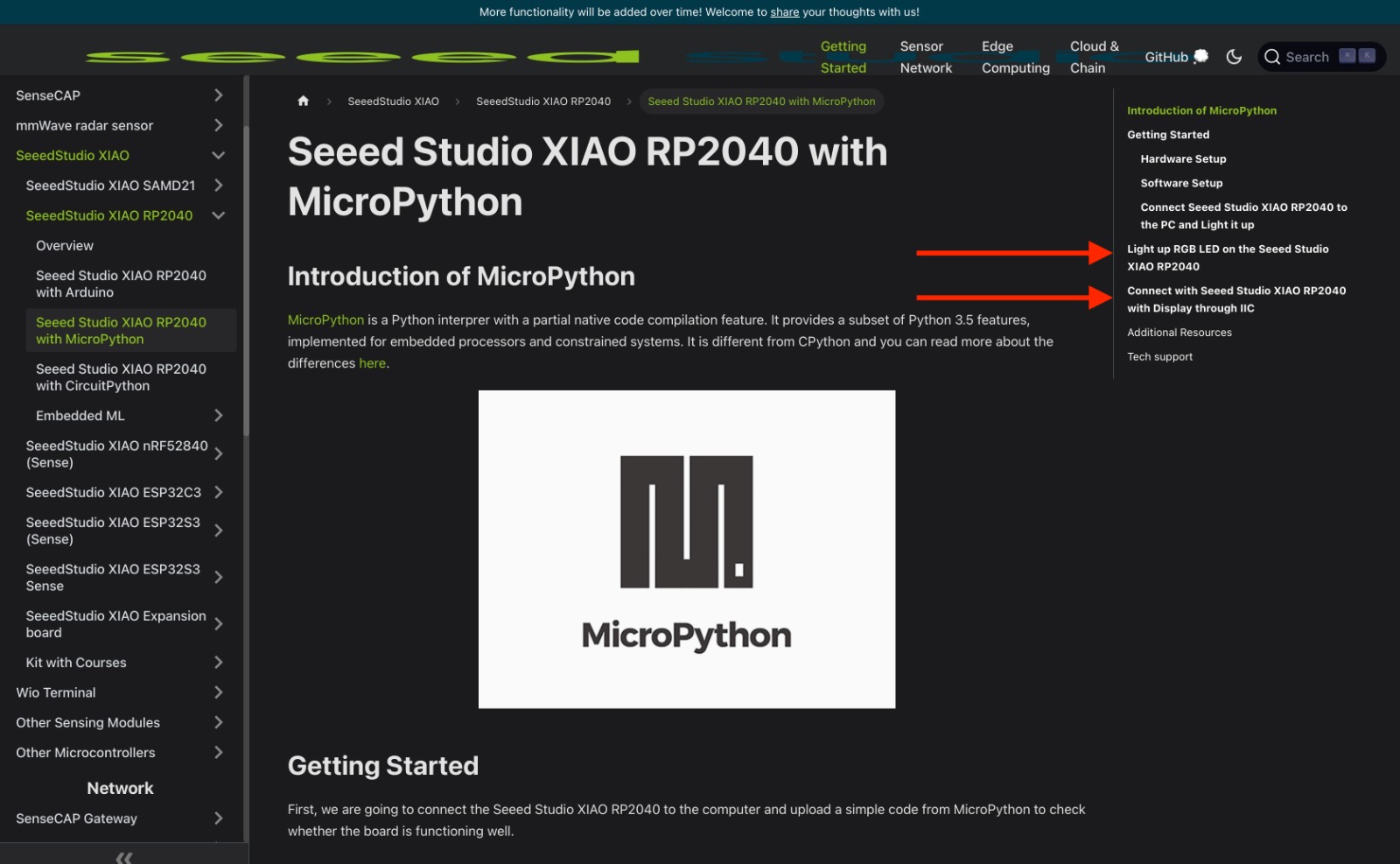
The documentations on Seeeduino official page
 help me a lot in programming the RGB led and in programming the Oled display.
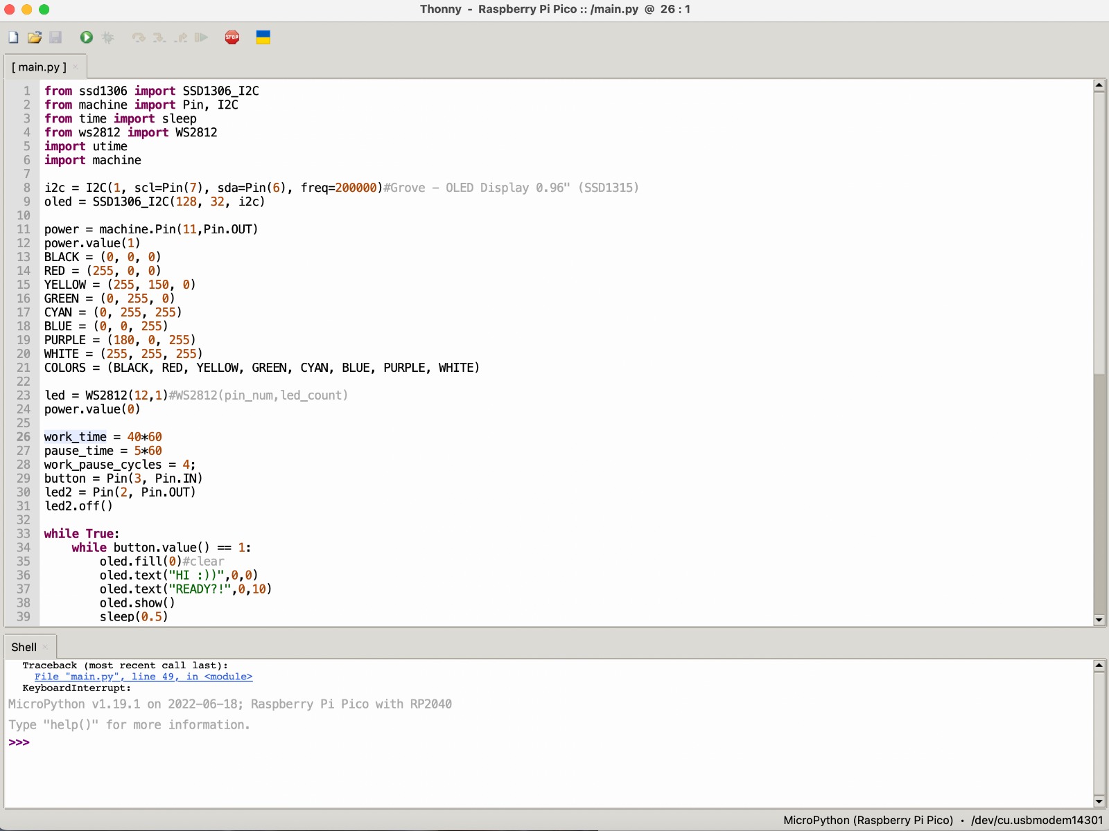
So, in Thonny, I used the Micropython libraries time, machine, ssd1306 and ws2812 I programmed the messages on the diplay.

In order to be more comfortable, I started programming the led to blik if the button is pressed.
I can use my PCB directly from the battery of my smartphone or from my mostly used devices.

Then, I started programming some guiding messages on the display to give to the user information on the coundown status and about the time left to the end of each phase.
Moreover the phases of the timer cycle are visually understandable from which led and color is turn on. Blue led means working time, white led pause and blinking RGB led means that one pause minute was gone.