Eletronics output
Assignment
Table of Content
- Group-Assigniment
- UALT&I2C ,SPI comunication
- PCB DESING IN KICARD &FILE PREPARATION TO GENERATE G -CODE, pcb printing
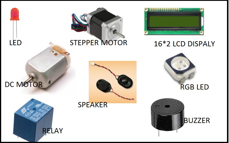
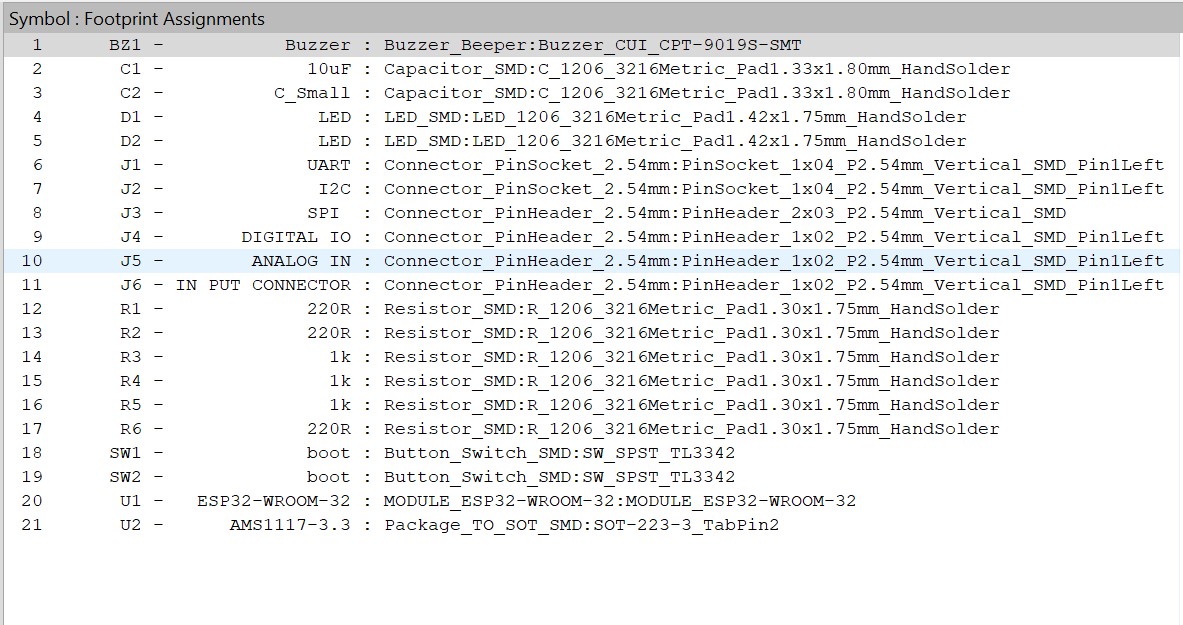
- list of component to be solderded
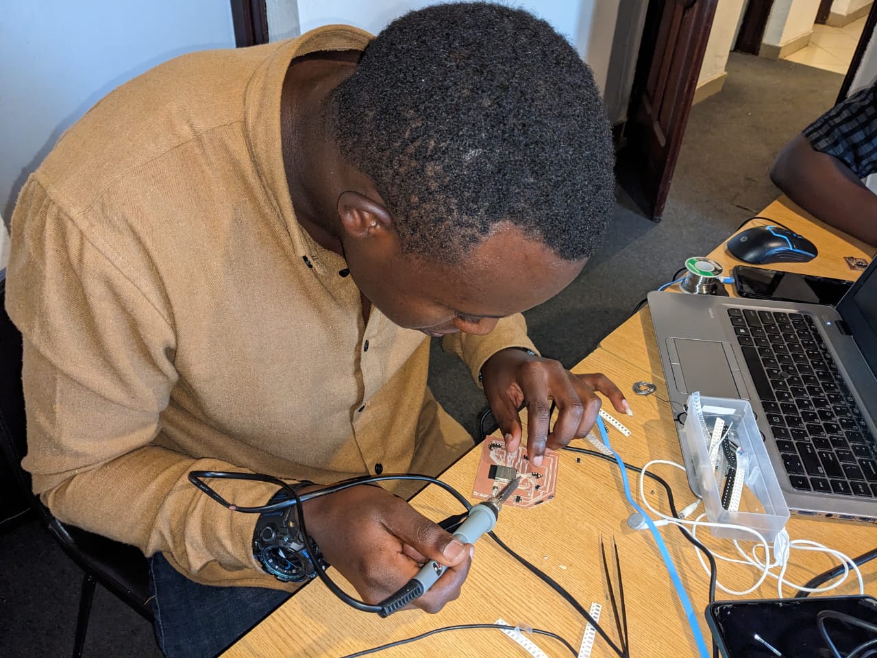
- PCB HAND SOLDELING AND TESTING
- DESCRIPTION OF OUTPUTS DEVICES AND PROGRAMING PROCEDURE
- servor motor
- Display with oleds
- work explanation
group assignmment
here we used to measure the voltage consumed with ic bellow you can find the link for more detail in group pageMaking an in-circuit programmer
DESIGN PROCEDURE OF MY DESIGN of my development board and circuit programmer
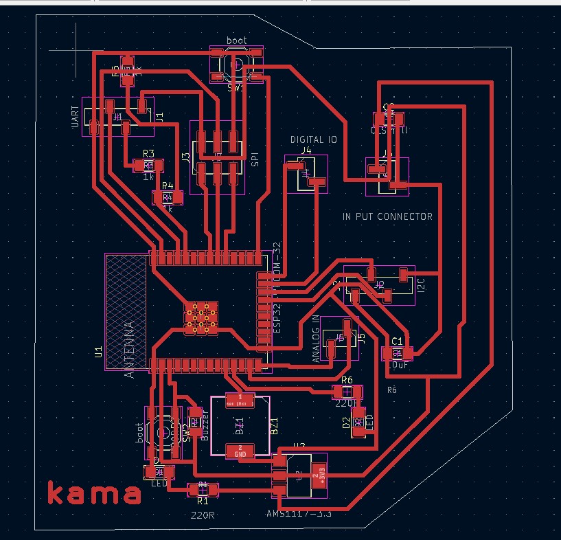
design procedure of my pcb board
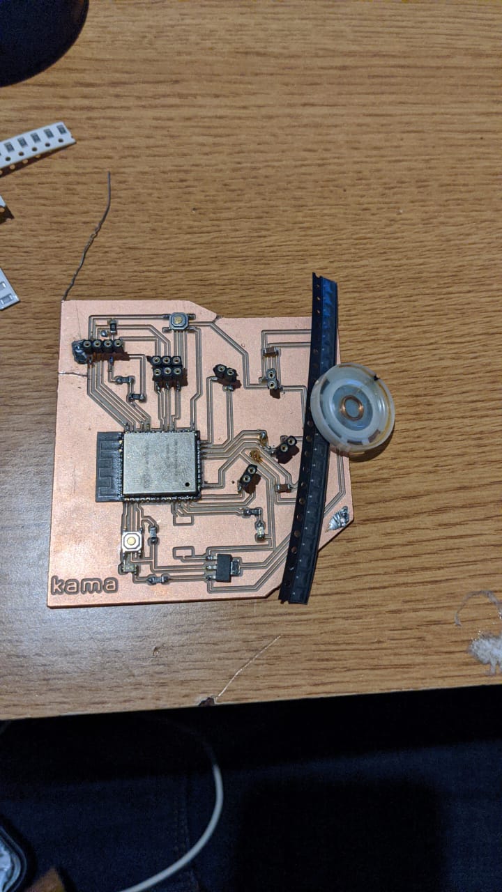
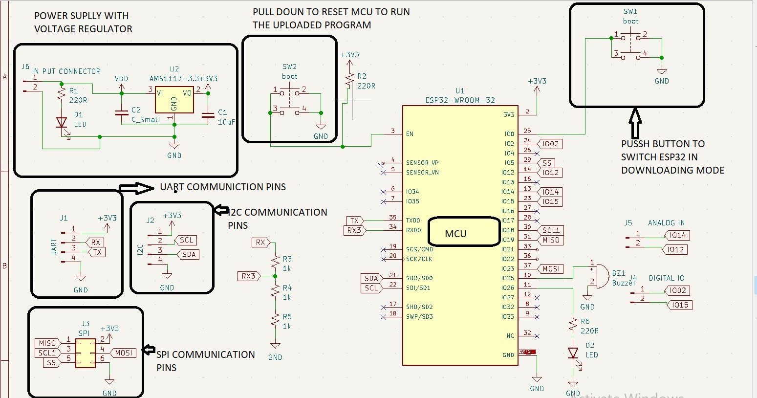
description circuit bord
here i would like to use esp32 microcontroller on my development board in order to interact with my out put (servor motor).there for my programmer designed before will convert the USB signal from your PC into UART communication so that i can program the ESP32 on the development board. This will allow me to send code and configuration information from your PC to the ESP32 using the chosen communication protocol of the microcontroller. The programmer will act as an interface between your PC and the ESP32, ensuring that the data is properly formatted and transmitted for successful programming.
Here you can find the procedure i used to design my dev-b
Design procedure of my programer
List of components
- esp32 MCU
- AMS1117 voltage regulator
- USB connector
- LED
- Capacitor (10uF)
- Resistor (optional)
my development board components list and thier foot prints
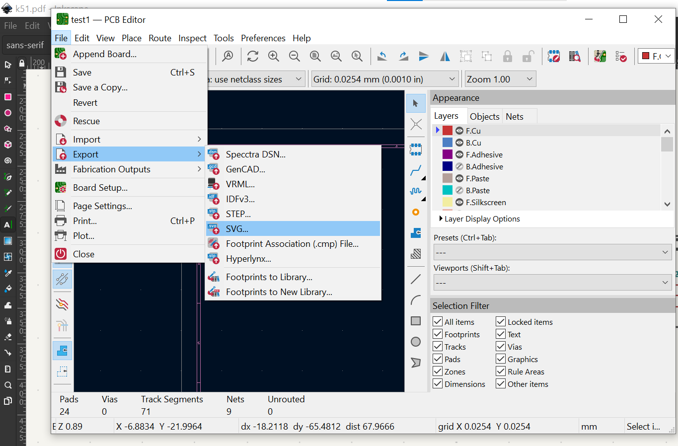
Exporting My PCB BOARD IN SVG FORMAT
- esp32 MCU
- AMS1117 voltage regulator
- USB connector
- LED
- Capacitor (10uF)
- Resistor (optional)
List of components
Exporting My PCB BOARD IN SVG FORMAT
Exporting your PCB board design in SVG (Scalable Vector Graphics) format can be useful for sharing your design with others who may not have access to KiCad software or including the design in a document or presentation. To export your PCB design in SVG format from KiCad, you can open the PCB layout editor, select "Export" from the File menu and choose "Export SVG." You can then customize the output file name, layers to be exported, and scale before generating the SVG file. Once exported, you can open the SVG file in a web browser or vector graphics editor for viewing and editing as needed.
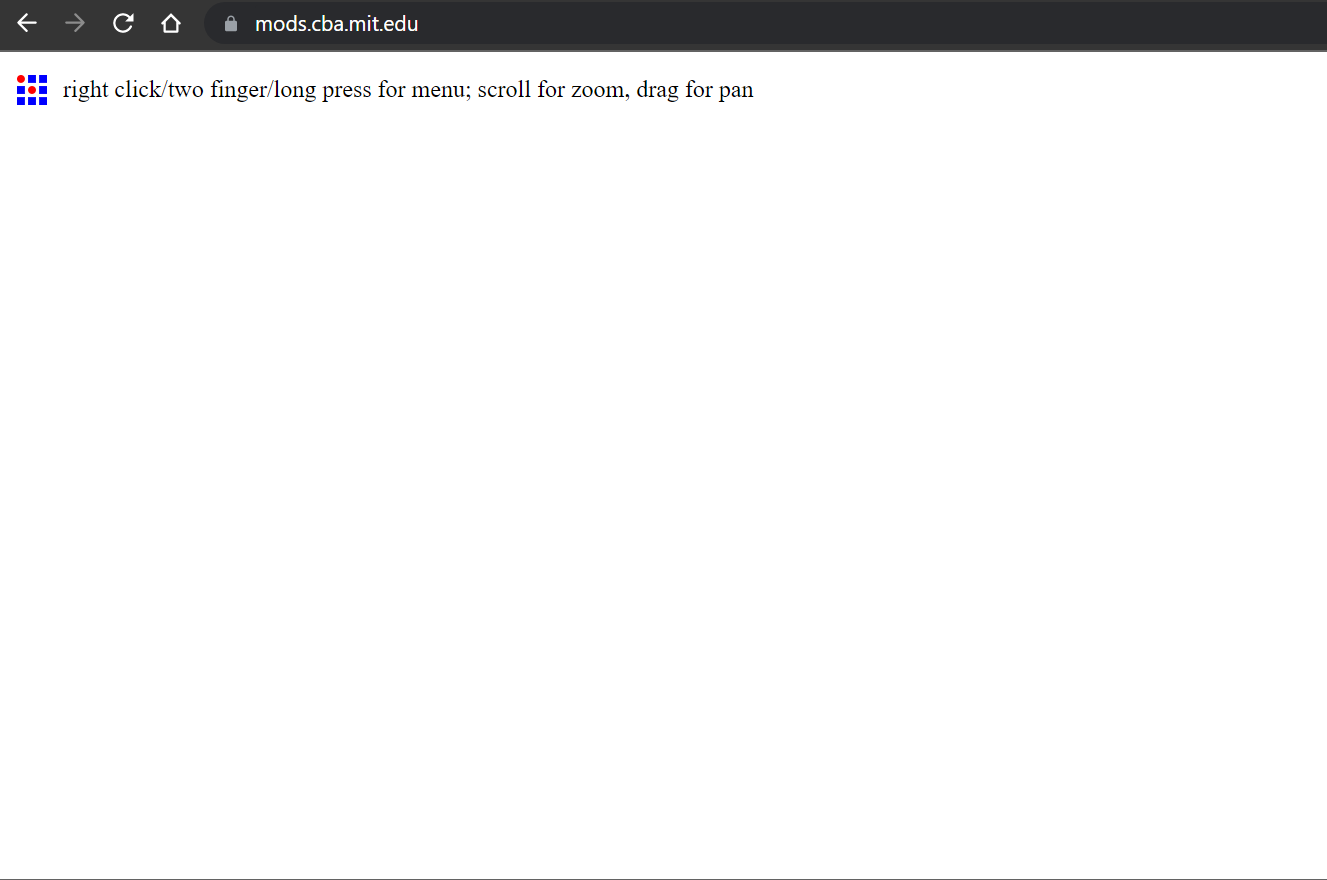
- Open your web browser and go tohttps://mods.cba.mit.edu/. This is the website for the Massachusetts Institute of Technology (MIT) Center for Bits and Atoms (CBA) Modular Machines program.
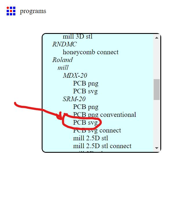
- Click on the "Mods" button on the top right corner of the screen, and then select "Roland" from the drop-down menu. Roland is a type of milling machine that uses G-code to operate.
- Once you've selected Roland , you'll be taken to the Roland module page. Click on the "Open Roland " button to open the Roland software.
- In the Roland software, click on the "File" menu and select "Import." Choose your SVG file from your computer and click "Open." Your SVG file will now be loaded into the Roland software.
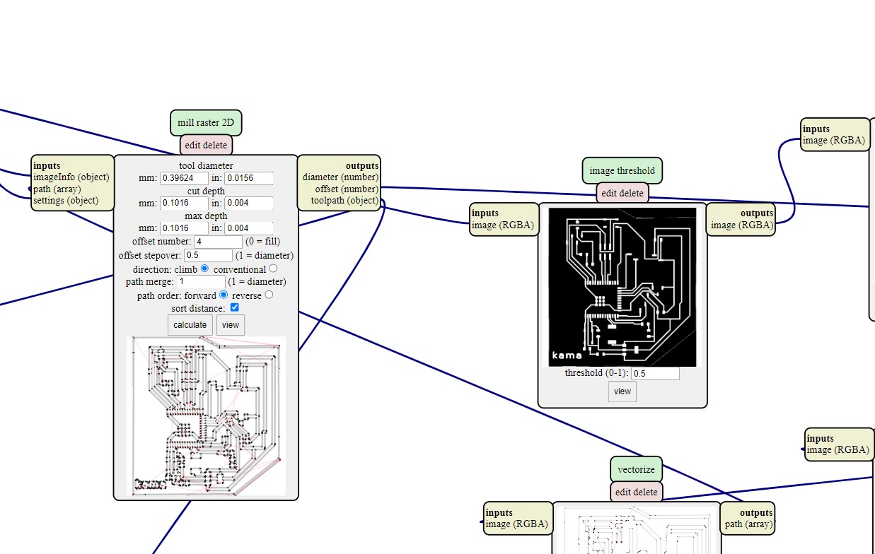
- after satisfied with my settings, click on the "Post" button to generate the G-code for your milling job. The G-code will be displayed in a new window.
- Copy the G-code and save it as a text file on your computer.
- Connect your Roland SRM-20 milling machine to your computer using a USB cable.and set the pcb work piece.
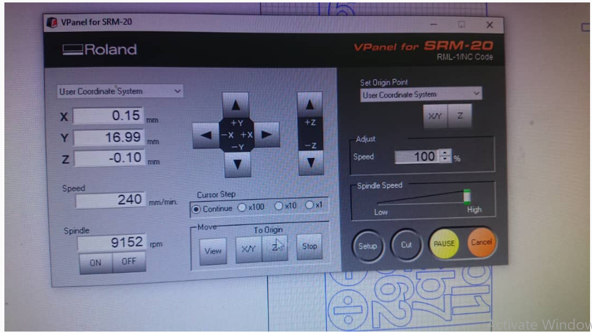
- Open the Roland SRM-20 software and click on the "File" menu. Select "Open" and choose the G-code file you just saved.
- Click on the "Send" button to send the G-code to your milling machine. The Roland SRM-20 will now start milling your design. and eletronic components soldering on designed pcb
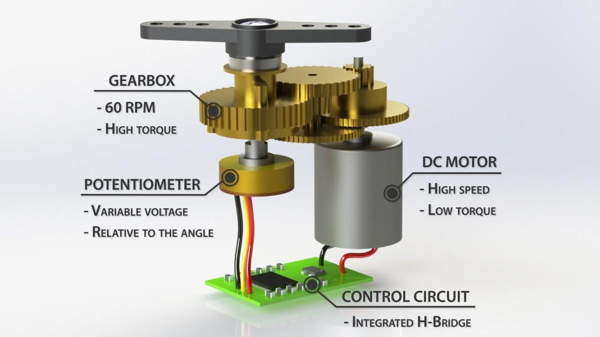
- servor motor:A Servo is a small device that has an output shaft. This shaft can be positioned to specific angular positions by sending the servo a coded signal.
As long as the coded signal exists on the input line,
the servo will maintain the angular position of the shaft.
As the coded signal changes, the angular position of the shaft changes
source: we reffered to this link https://archive.seattlerobotics.org/guide/servos.htmlimage source:
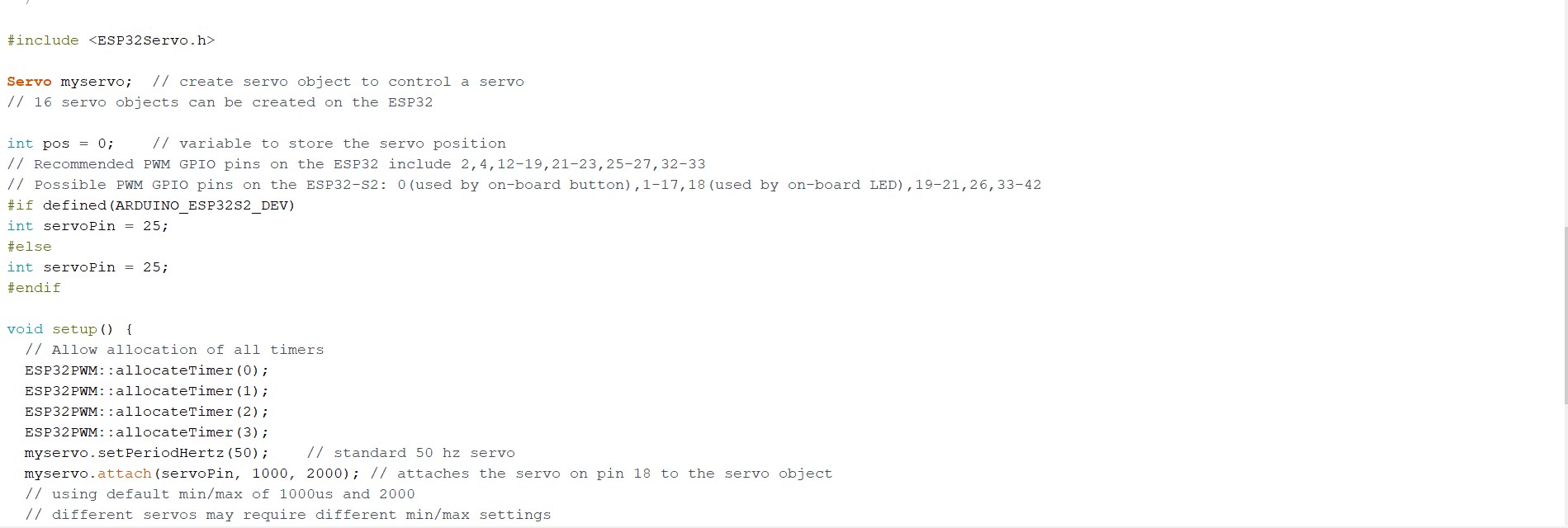
PROGRAMING SECTION
here you can find the code used to run servor mortor by using arduino
 here you can find the video which shows
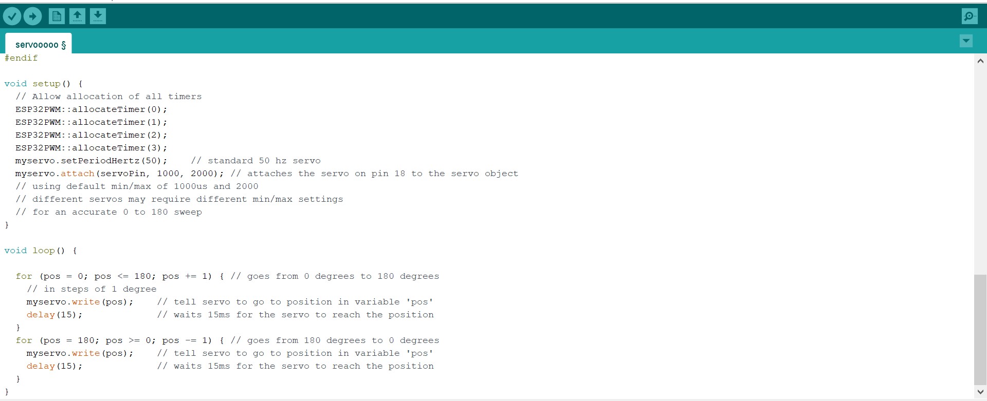
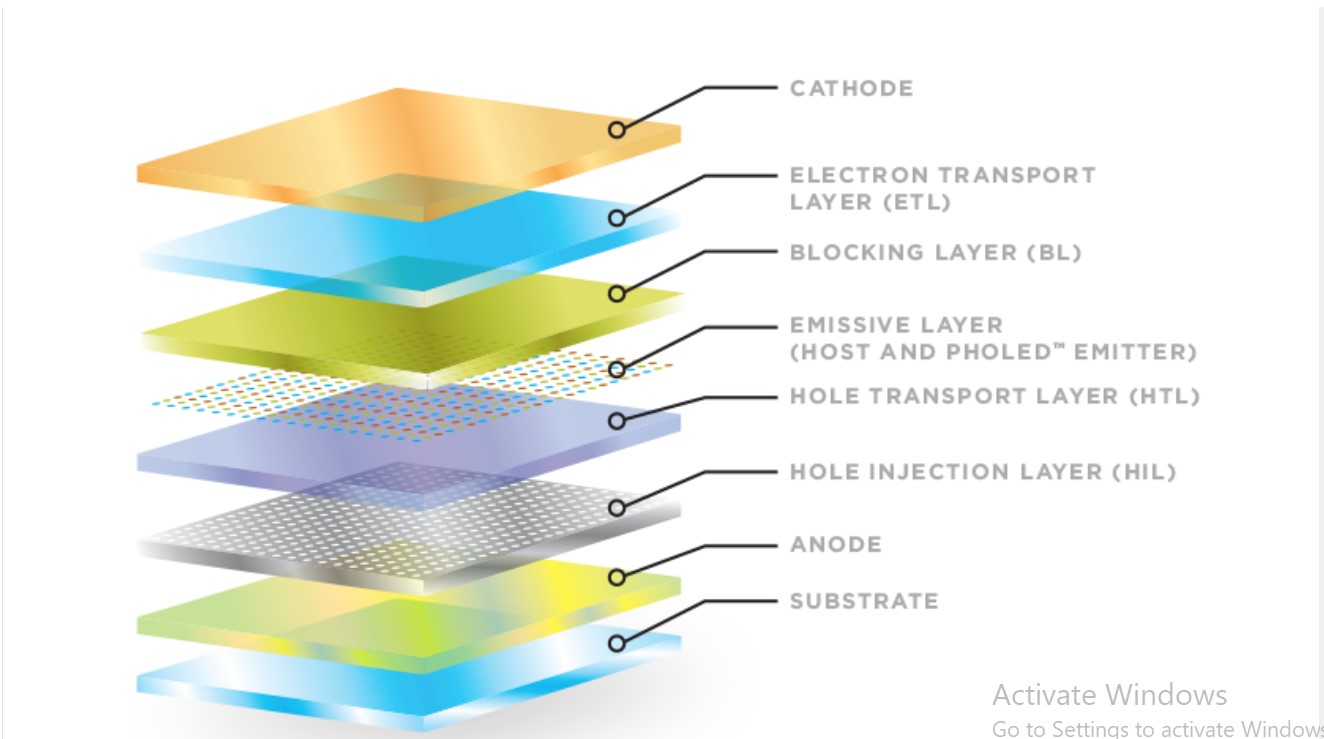
using ORGANIC LIGHT EMITTING DIODES (OLEDS)
Organic light emitting diodes (devices) or OLEDs are monolithic, solid-state devices that typically consist of a series of organic thin films sandwiched between two thin-film conductive electrodes. When electricity is applied to an OLED, under the influence of an electrical field, charge carriers (holes and electrons) migrate from the electrodes into the organic thin films until they recombine in the emissive zone forming excitons. Once formed, these excitons, or excited states, relax to a lower energy level by giving off light (electroluminescence) and/or unwanted heat.
working principle of oleds
the referrence of all information is here :
https://oled.com/oleds/configuration of my circuit with oled display integrated my dev board
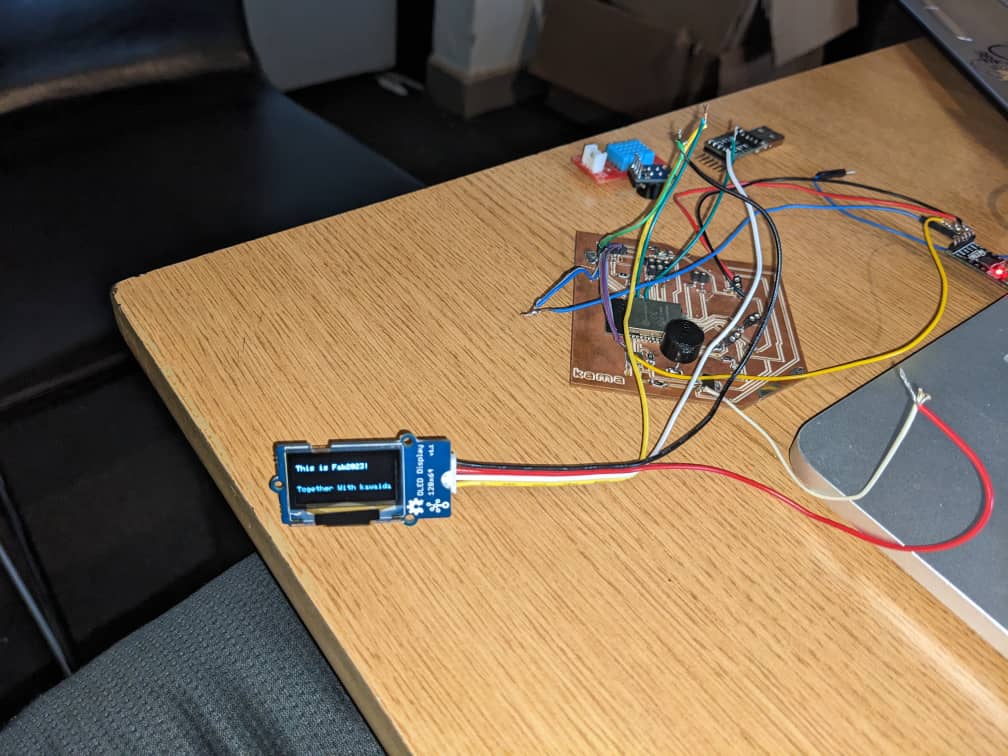
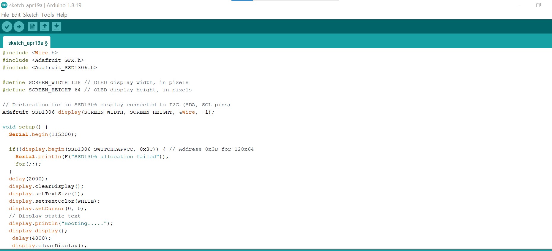
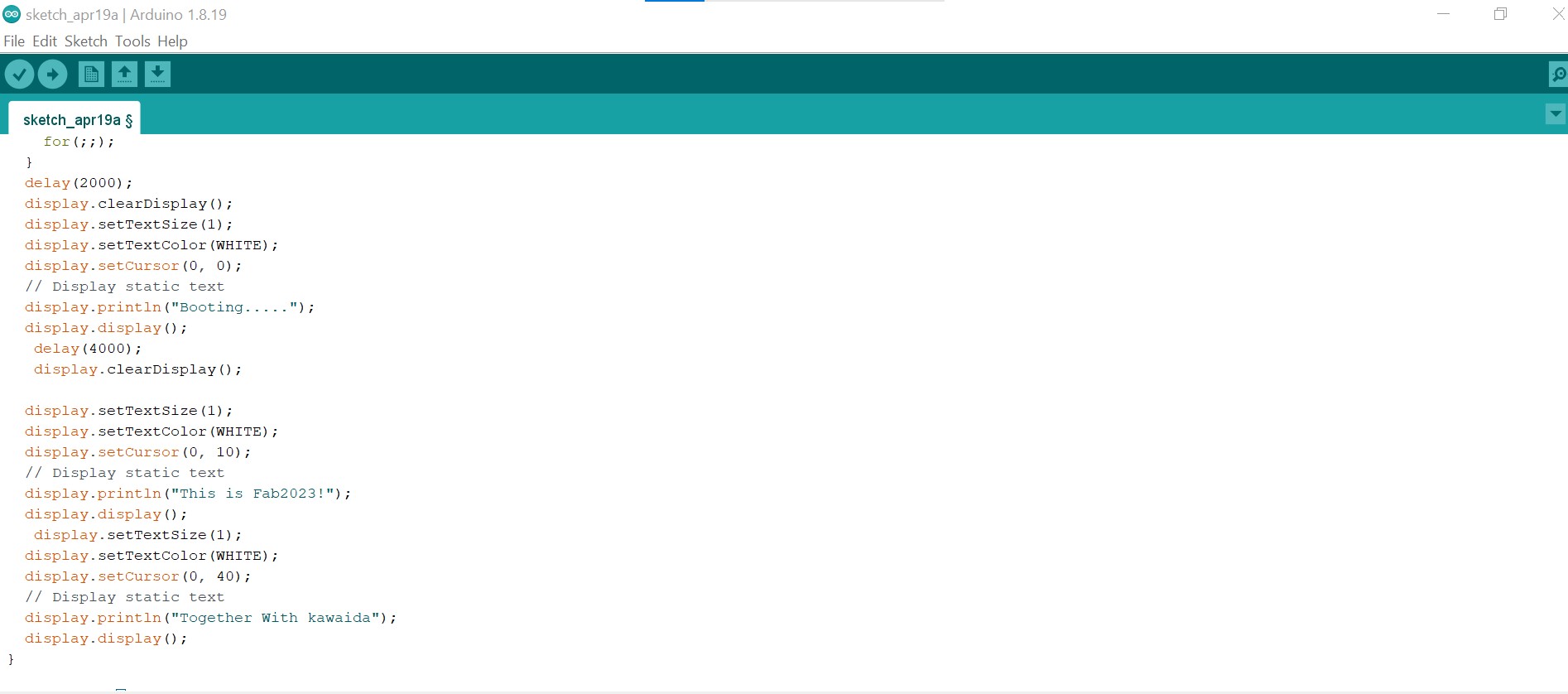
program used for displaying somethings
the description of this out put is mentioned in this video
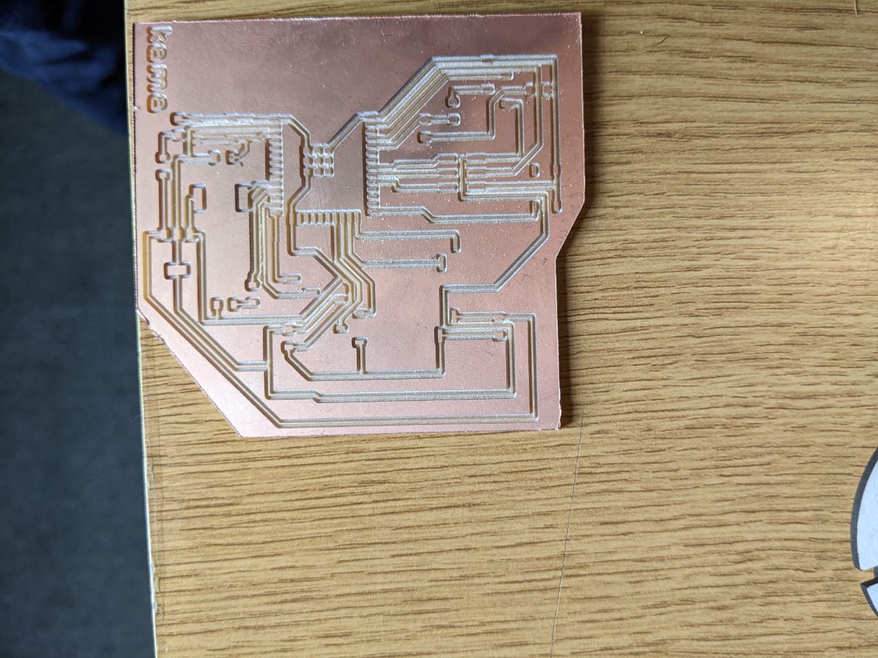
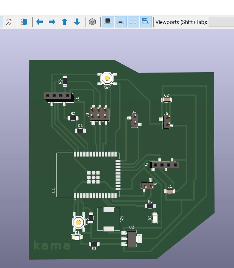
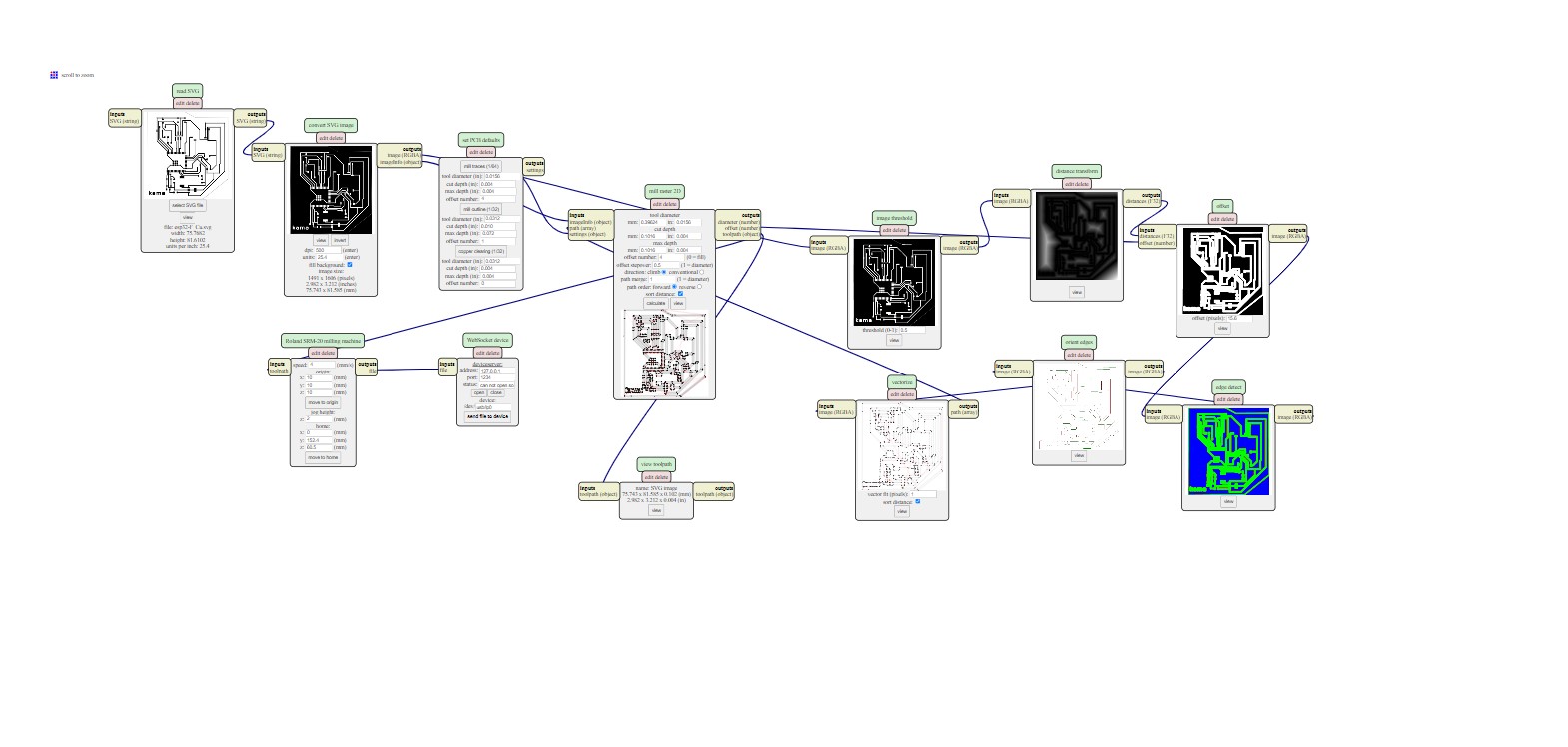
afte exporting my pcb board in svg format the is a process used to convert svg into G-CODE
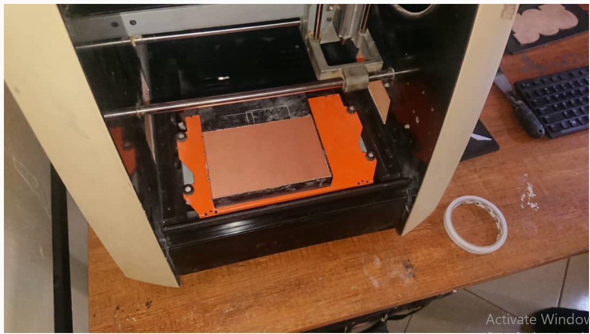
this is a picture of DELELOPMENT BOARD AFTER PRINTING