Eletronics Design
Assignment
more detail will shown on class link
IN our lab the instructor explains the major fator to Characterize the design rules for your in-house PCB production process: feeds, speeds, plunge rate, depth of cut (traces and outline) and tooling.

Individual assignment
Table of Content
- Testing the compact milling machine (Group-Assigniment)
- Detailed aspecs of the machine(Group-Assigniment)
- Making an in-circuit programmer(Individual work)
- UALT&I2C ,SPI comunication
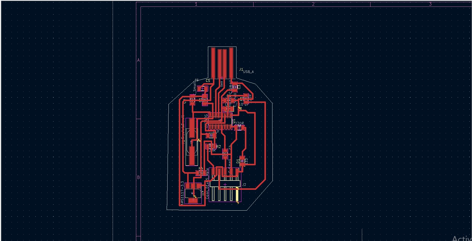
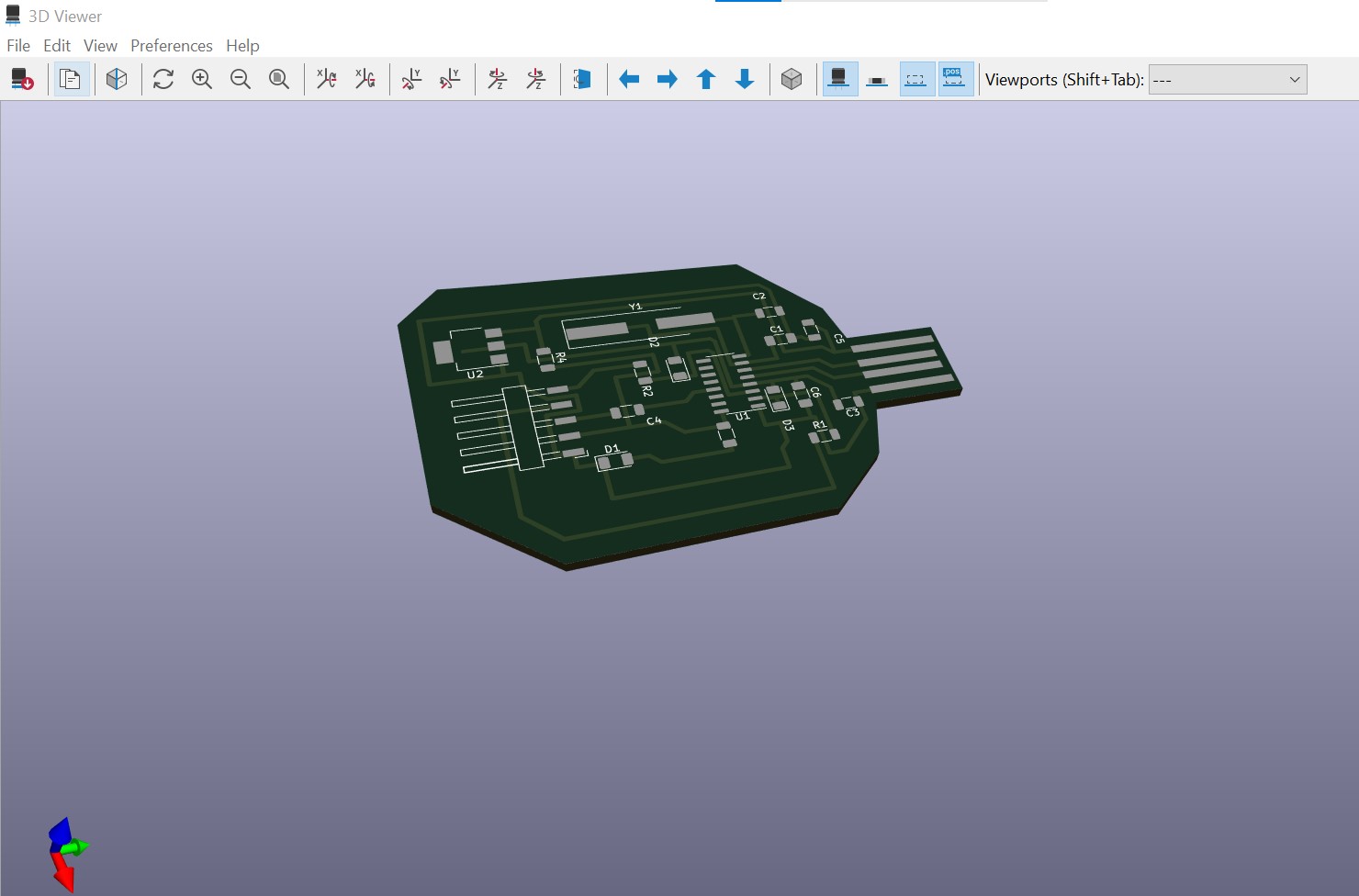
- PCB DESING IN KICARD
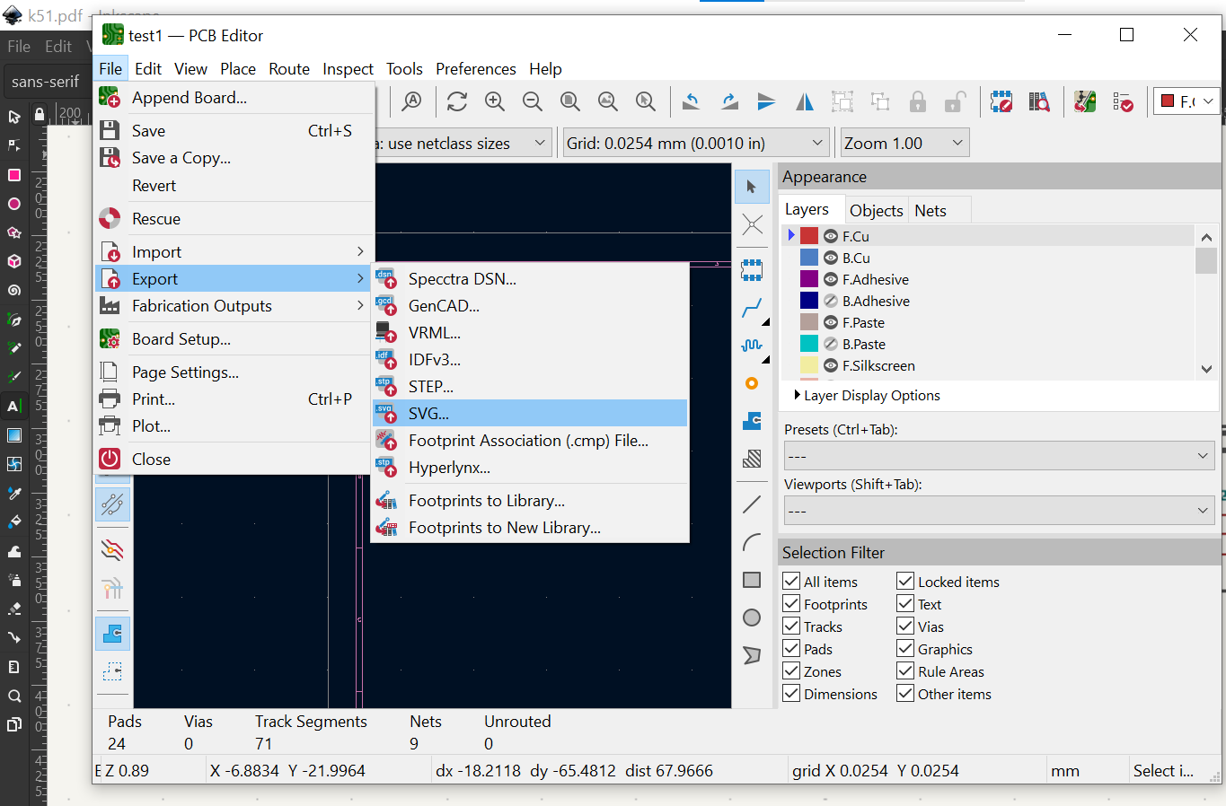
- FILE PREPARATION TO GENERATE G -CODE
- MACHINE SETTING FOR PCB PRINTING/li>
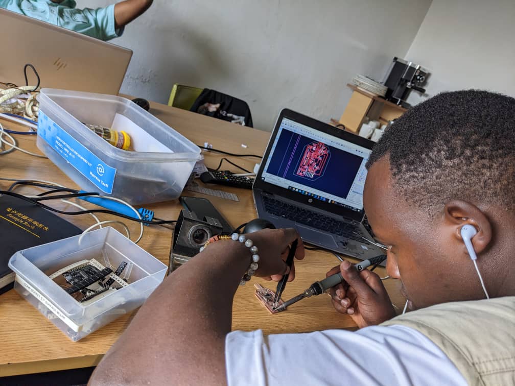
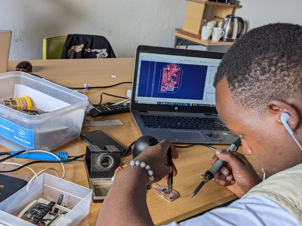
- PCB HAND SOLDELING AND TESTING
Making an in-circuit programmer
DESIGN PROCEDURE OF MY DESIGN of my development board and circuit programmer
UALT&I2C ,SPI comunication

UART, which stands for Universal Asynchronous Receiver-Transmitter, is a simple and widely used communication protocol for serial data transmission. It uses two wires to transmit data, one for sending and one for receiving, and does not require a clock signal. UART is often used to communicate between a microcontroller and a peripheral device, such as a sensor or motor. The communication is asynchronous, meaning that data is transmitted without a fixed timing relationship between the sender and receiver
I2C, or Inter-Integrated Circuit, is a synchronous communication protocol commonly used to connect multiple devices on a single bus. It uses two wires, one for data and one for clock, to transmit data between devices. I2C allows multiple devices to share the same communication bus, and each device is identified by a unique address. The communication is also synchronous, meaning that the sender and receiver are synchronized to a common clock signal.
SPI, or Serial Peripheral Interface, is a synchronous communication protocol commonly used to communicate between microcontrollers and peripheral devices such as sensors, LCD displays, and flash memory. It uses four wires to transmit data, including a clock signal, a data signal, and two control signals. The communication is synchronous, meaning that the sender and receiver are synchronized to a common clock signal. SPI allows for high-speed data transmission and is often used for applications that require fast and reliable communication
UALT&I2C ,SPI comunication table of defference

design procedure of my circuit programer
reason why to design its programer
bleifly ,my programmer will convert the USB signal from your PC into UART communication so that i can program the ESP32 on the development board. This will allow me to send code and configuration information from your PC to the ESP32 using the chosen communication protocol of the microcontroller. The programmer will act as an interface between your PC and the ESP32, ensuring that the data is properly formatted and transmitted for successful programming.
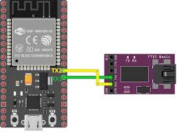
Here you can find the procedure i used to design programmer board
Design procedure of my programer
List of components
- CH340C programmer
- AMS1117 voltage regulator
- USB connector
- LED
- Capacitor (10uF)
- Resistor (optional)
schematic diagram of programer
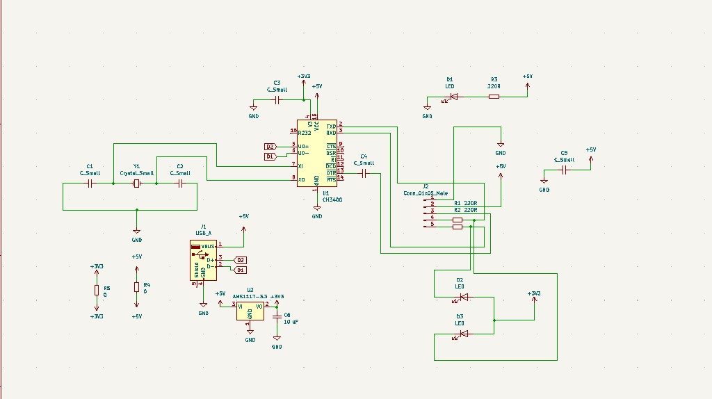
- CH340C programmer
- AMS1117 voltage regulator
- USB connector
- LED
- Capacitor (10uF)
- Resistor (optional)
List of components

