Embedded Programming
Assignment
- Group-Assigniment
- The instructor exprains deeply the difference between microcontroller and microprocessor which is explained bellow
- Microprocessor consists of only a Central Processing Unit, whereas Micro Controller contains a CPU, Memory, I/O all integrated into one chip.
- Microprocessor is used in Personal Computers whereas Micro Controller is used in an embedded system.
- Microprocessor uses an external bus to interface to RAM, ROM, and other peripherals, on the other hand, Microcontroller uses an internal controlling bus.
- Microprocessors are based on Von Neumann model Micro controllers are based on Harvard architecture for more detail you can refer's to link bellow = MICRO PROCESSER VS MICRO CONTROLLER
- Internal SRAM: The ESP32 has 520KB of internal SRAM memory, divided into different banks. The clock speed of the internal SRAM is up to 240 MHz.
- Internal Flash Memory: The ESP32 has up to 4MB of internal flash memory for storing program code and other data. The clock speed of the internal flash memory is up to 80 MHz.
- External SPI Flash Memory: The ESP32 can also be connected to an external SPI flash memory, which can provide additional storage for program code, data, and other files. The clock speed of the external SPI flash memory can be up to 80 MHz.
- PSRAM: Some ESP32 modules also include an external PSRAM chip, which can provide additional high-speed memory for data and other purposes. The clock speed of the PSRAM is up to 80 MHz.
- 36 GPIO pins, which can be used for both digital and analog I/O functions.
- Some of these GPIO pins are also connected to other hardware peripherals, such as the SPI and I2C interfaces, UART, and PWM outputs.
- General Purpose Input / Output Interface (GPIO).
ESP32 has 34 GPIO pins which can be assigned various functions by programming the appropriate registers. There are several kinds of GPIOs: digital-only, analog-enabled, capacitive-touch-enabled, etc. Analog-enabled GPIOs and Capacitive-touch-enabled GPIOs can be configured as digital GPIOs. - Analog-to-Digital Converter (ADC).
ESP32 integrates 12-bit SAR ADCs and supports measurements on 18 channels (analog-enabled pins). The ULP coprocessor in ESP32 is also designed to measure voltage, while operating in the sleep mode, which enables low-power consumption. The CPU can be woken up by a threshold setting and/or via other triggers. With appropriate settings, the ADCs can be configured to measure voltage on 18 pins maximum. - Ethernet MAC Interface.
An IEEE-802.3-2008-compliant Media Access Controller (MAC) is provided for Ethernet LAN communications. ESP32 requires an external physical interface device (PHY) to connect to the physical LAN bus (twisted-pair, fiber, etc.). The PHY is connected to ESP32 through 17 signals of MII or nine signals of RMII. The following features are supported on the Ethernet MAC (EMAC) interface: - Universal Asynchronous Receiver Transmitter (UART).
ESP32 has three UART interfaces, i.e., UART0, UART1 and UART2, which provide asynchronous communication (RS232 and RS485) and IrDA support, communicating at a speed of up to 5 Mbps. UART provides hardware management of the CTS and RTS signals and software flow control (XON and XOFF). All of the interfaces can be accessed by the DMA controller or directly by the CPU. - Wi-Fi: The ESP32 has built-in Wi-Fi connectivity, which allows it to connect to wireless networks and communicate with other devices over the internet. The Wi-Fi protocol is used for wireless networking and is based on the IEEE 802.11 standards.
- Bluetooth: The ESP32 also supports Bluetooth communication, which allows it to connect to other Bluetooth-enabled devices such as smartphones, tablets, and laptops. The Bluetooth protocol is used for short-range wireless communication and is based on the Bluetooth standard.
- Serial: The ESP32 has several UART interfaces, which can be used for serial communication with other devices. Serial communication involves sending and receiving data one bit at a time over a wired or wireless connection.
- I2C: The ESP32 also supports the I2C protocol, which is a popular protocol for communication between microcontrollers and sensors or other devices. I2C is a two-wire interface that allows multiple devices to be connected to the same bus, which can simplify wiring and reduce the number of pins required.
- SPI: The ESP32 also supports the SPI protocol, which is another popular protocol for communication between microcontrollers and other devices. SPI is a high-speed synchronous interface that is commonly used for communication with sensors, memory devices, and other peripherals.
- Install the Arduino IDE: If you haven't already, download and install the Arduino IDE from the official website: dounload arduino ide Make sure you download the correct version for your operating system.
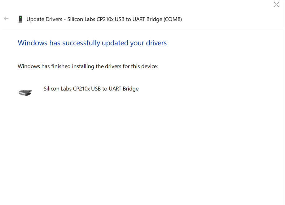
- after apdating the port drives in my pc with the help of devise manager then port search for
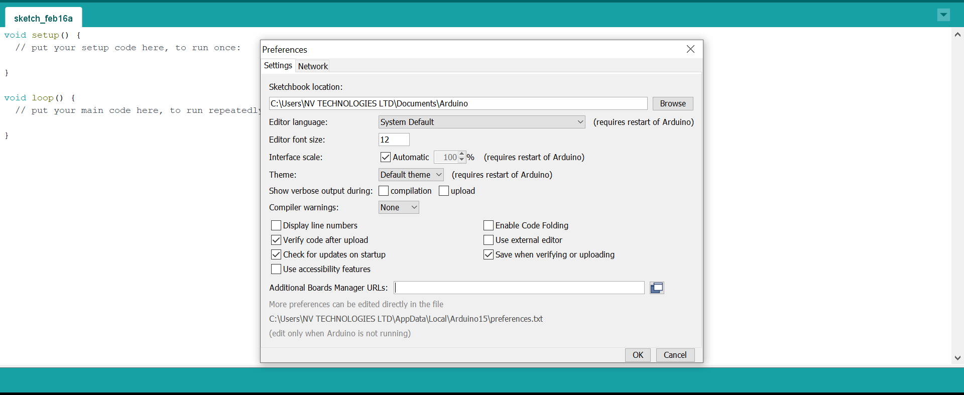
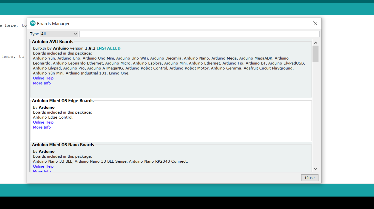
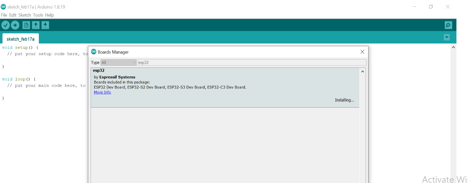
Install the ESP32 Board Package: Open the Arduino IDE and go to "File" > "Preferences". In the "Additional Board Managers URLs" field, enter the following URL and click "OK": link arduino ide and esp32 board . Then go to "Tools" > "Board" > "Boards Manager...", search for "esp32" and install the "ESP32" board package. - Select the ESP32 Board: After installing the board package, go to "Tools" > "Board" and select the appropriate ESP32 board from the list.
- Connect the ESP32 Board: Connect your ESP32 board to your computer using a USB cable. If necessary, install any drivers that may be required for your specific board.
- Upload Your Sketch: Write your sketch code in the Arduino IDE and click the "Upload" button to upload the code to the ESP32 board. If all goes well, the code will be compiled and uploaded to the board, and you should see the output in the Serial Monitor.
- ESP32 development board
- Breadboard
- 220 ohm resistor
- Push button switch
- Jumper wires
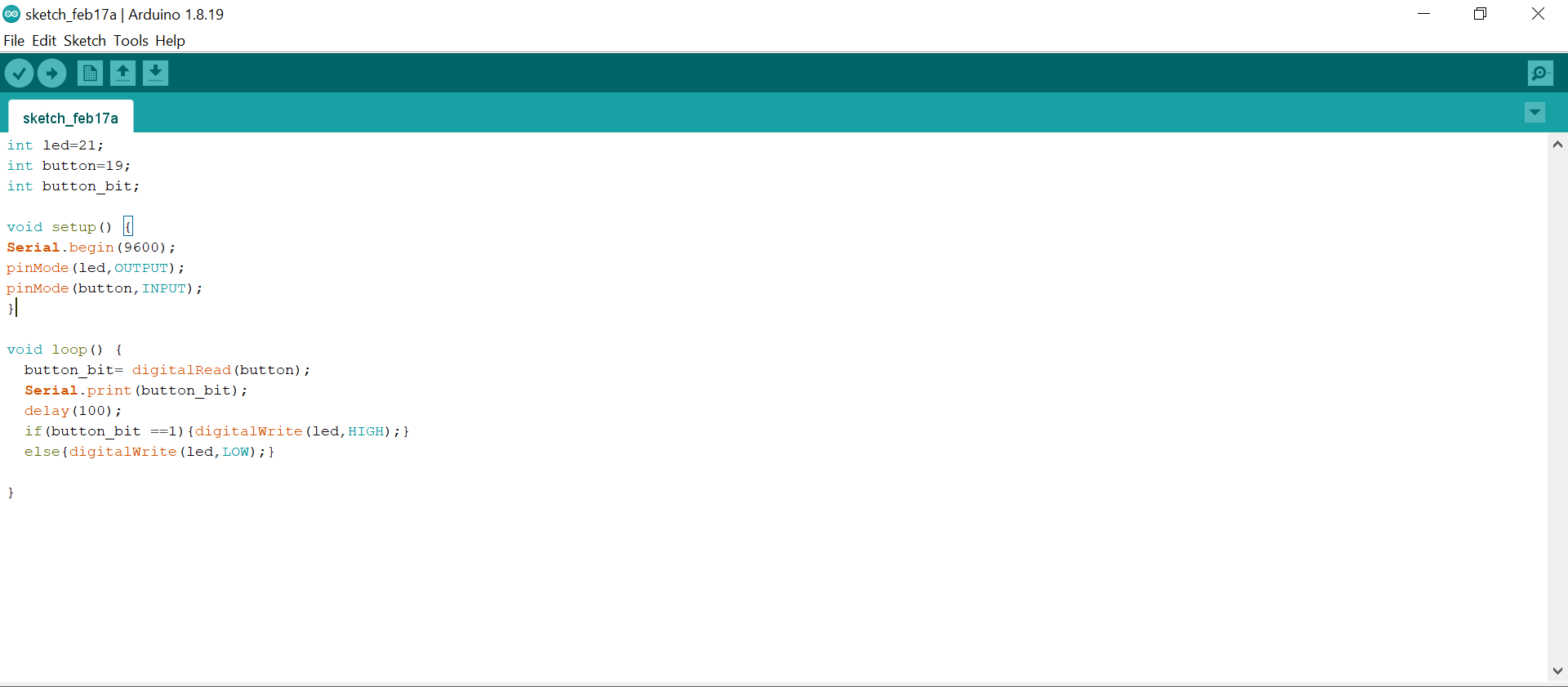
- Connect the positive leg of the LED to pin 21 of the ESP32, and the negative leg to ground through a 220 ohm resistor.
- Connect one pin of the push button switch to ground, and the other pin to pin 19 of the ESP32
- Connect a pull-up resistor (e.g. 10k ohm) between pin 12 and 3.3V to ensure that the input is pulled high when the switch is not pressed.
- Upload the following code to the ESP32:
- After uploading the code, press the push button switch to turn the LED on and off. This code sets up the LED and switch pins as inputs and outputs, respectively. It then reads the state of the switch and compares it to the previous state to check if the button has been pressed or released. If the button has been pressed, the code toggles the state of the LED by inverting the current state using the "!" (not) operator. Finally, a small delay is added to debounce the switch and prevent it from registering multiple presses.
- Connect the lamp to a relay module, and connect the relay module to the ESP32 using a suitable pins5 ,pin 4
- Set up your ESP32 as a web server by including the following
libraries at the beginning of your
code:
#include
#include
- Set up the WiFi connection by including the following code in your setup() function:
- Define the web server by creating a WebServer object and specifying the port number
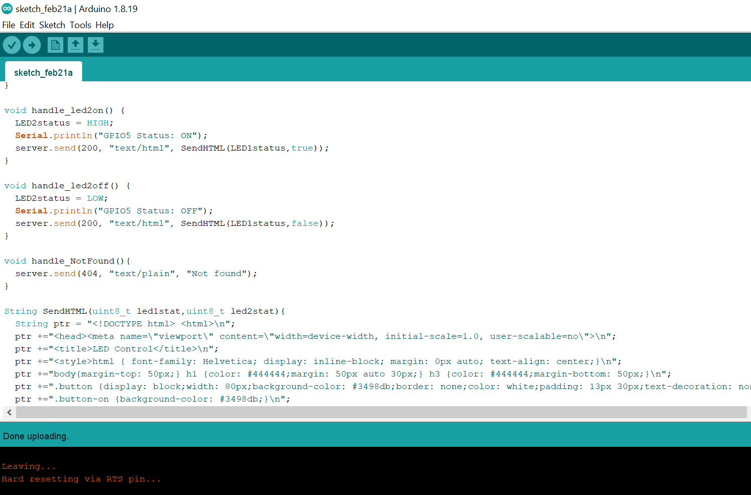
- In your setup() function, add a handler for the root URL ("/") that serves a basic HTML page with a button to control the lamp
- Add handlers for the "/on" and "/off" URLs that toggle the state of the lamp and Replace "relayPin" with the pin number that is connected to the relay module.
- Start the server in your setup() function:
- Add the following code to your loop() function to handle incoming requests:
- Upload the code to your ESP32 and open the Serial Monitor to see the ESP32's IP address. Type this address into a web browser to access the web server
more detail will shown on class link
IN our lab the instructor advice as to use one of microcontroller type colled esp32 becouse of it advantage of having bruetooth and weif which the user to access data and monitoring remotely.
Individual assignment
data sheet learning out come.
name of micro controler
Esp32 is the name of micro controller used. After reading data sheet we fund more detail conserns the name of manufcctuer , the operating frequancy and micro controller performance capabillity even other parmeters which is going to be mationed bellow .ESP32 is a single 2.4 GHz Wi-Fi-and-Bluetooth combo chip designed with the TSMC ultra-low-power 40 nm technology. It is designed to achieve the best power and RF performance, showing robustness, versatility and reliability in a wide variety of applications and power scenarios. futhermore, there are chips mounted inside such us ESP32-D0WDQ6, ESP32-D0WD, ESP32-D2WD, and ESP32-S0WD for its more detail here you can find the link Esp32 data sheet
ESP32 architecture
The ESP32 is a dual-core microcontroller with a Xtensa LX6 CPU architecture. It features two Tensilica Xtensa LX6 cores, which can be clocked up to 240 MHz, and has a variety of on-board peripherals, including Wi-Fi, Bluetooth, and various other digital and analog interfaces. The architecture is designed to provide a balance of performance and power efficiency, making it well-suited for a wide range of applications, from IoT devices to industrial automation and beyond.
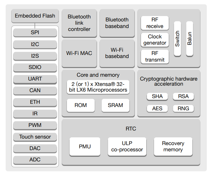
ESP32 Functional Block Diagram
Esp32 memories types and its clock speed
regarding to the esp32 datasheet this microcontroller contains four type of memories which its faction and clock speed describede bellow
It's important to note that the clock speeds of these different types of memory can vary depending on the specific implementation and configuration of the ESP32 module being used.
ESP32 Pins and its classifications
The number of digital and analog pins on an ESP32 module can vary depending on the specific implementation and configuration of the module, but most commonly used ESP32 development boards have the following pin configuration:
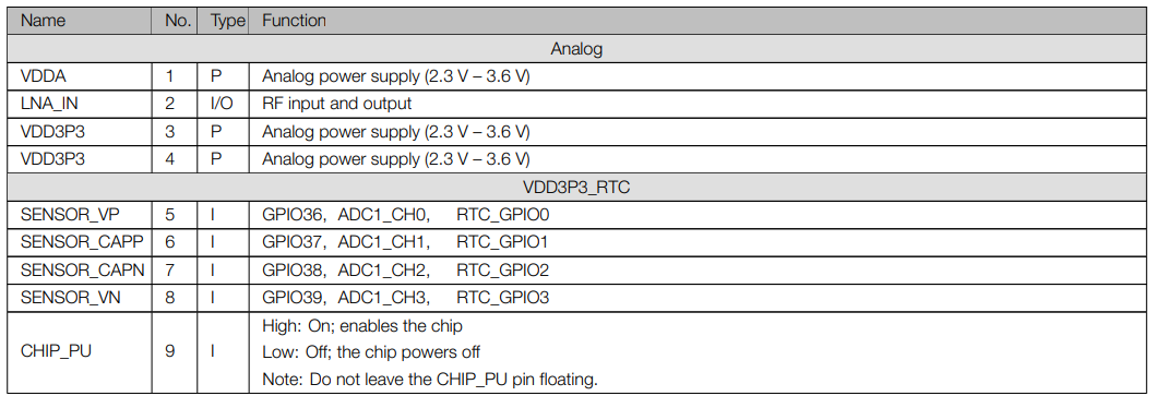
MCU pins and its meaning
The exact number of pins available on an ESP32 module may vary depending on the specific implementation and configuration of the module, but most commonly used ESP32 development boards have 34 GPIO pins.
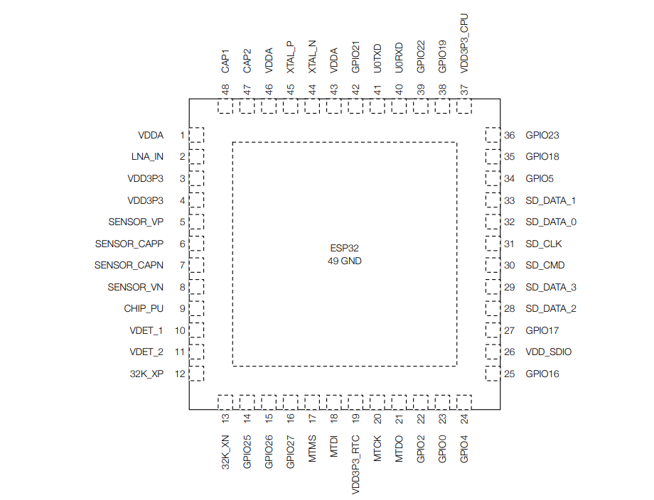
microcontroller have 48 pins on it, where by you are expected to attach power connections, input and output connections, and communications connections. esp32 microcontroller has different configurations for its pins as shown above. one pin can have more than one functionhere you can determine the number of pins as it matione bellow from data sheet
2. Peripherals and Sensors
ESPE32 COMMUNICATION PROTOCAL
he ESP32 microcontroller supports a wide range of communication protocols, making it well-suited for a variety of IoT and embedded applications. Here are a few examples of commonly used communication protocols with the ESP32:
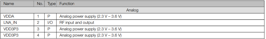
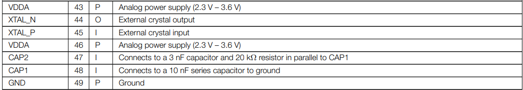
1.MICRO CONTROLLER ELETRICITY CHARACTERISTIC (POWER SUPLLY)
the main issue you have to focus on is to know the voltage your micro controller is operating with and voltage needed for supply. on esp32 the supply voltage on specified pin is shown below there is table from data sheet.
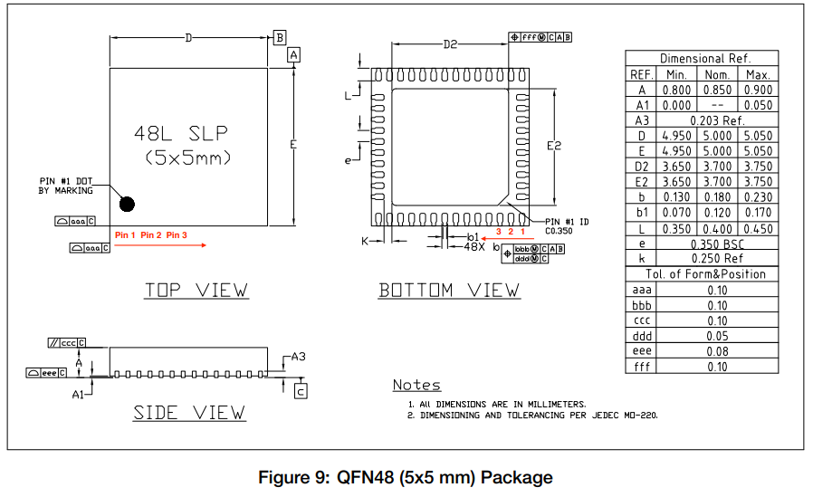
Package Information
Confuguration of my esp32 develpment bord for interation and comunication between arduino ide and board.
introdution on aruduino
Arduino is an open-source electronics platform that consists of a programmable microcontroller board, software development environment, and a community of users and developers. The platform is designed to make it easy for anyone, including beginners, to create interactive electronic projects. The Arduino board itself is typically a small, inexpensive computer that can be connected to various electronic components such as sensors, LEDs, motors, and other devices. The board can be programmed using a simplified version of the C++ programming language, which allows users to control the behavior of their electronic projects. The Arduino platform has gained popularity among hobbyists, educators, and professionals due to its ease of use, low cost, and versatility. It has been used in a wide variety of projects, ranging from simple LED displays to complex robots and automation systems.
on this stage the job is interestin , it was my first use srduino in my computer the process usede to install arduino IDE and connecting it with esp32 development board are mationed bellow.

first exercises
after gathered all the required materials, i follow these steps to wire up the circuit and program the ESP32:
second exercises
To use ESP32 as a web server to control my room lamps, here you can follow these process to control yours

Replace "your_SSID_here" and "your_PASSWORD_here" with your own WiFi credentials.
web interface
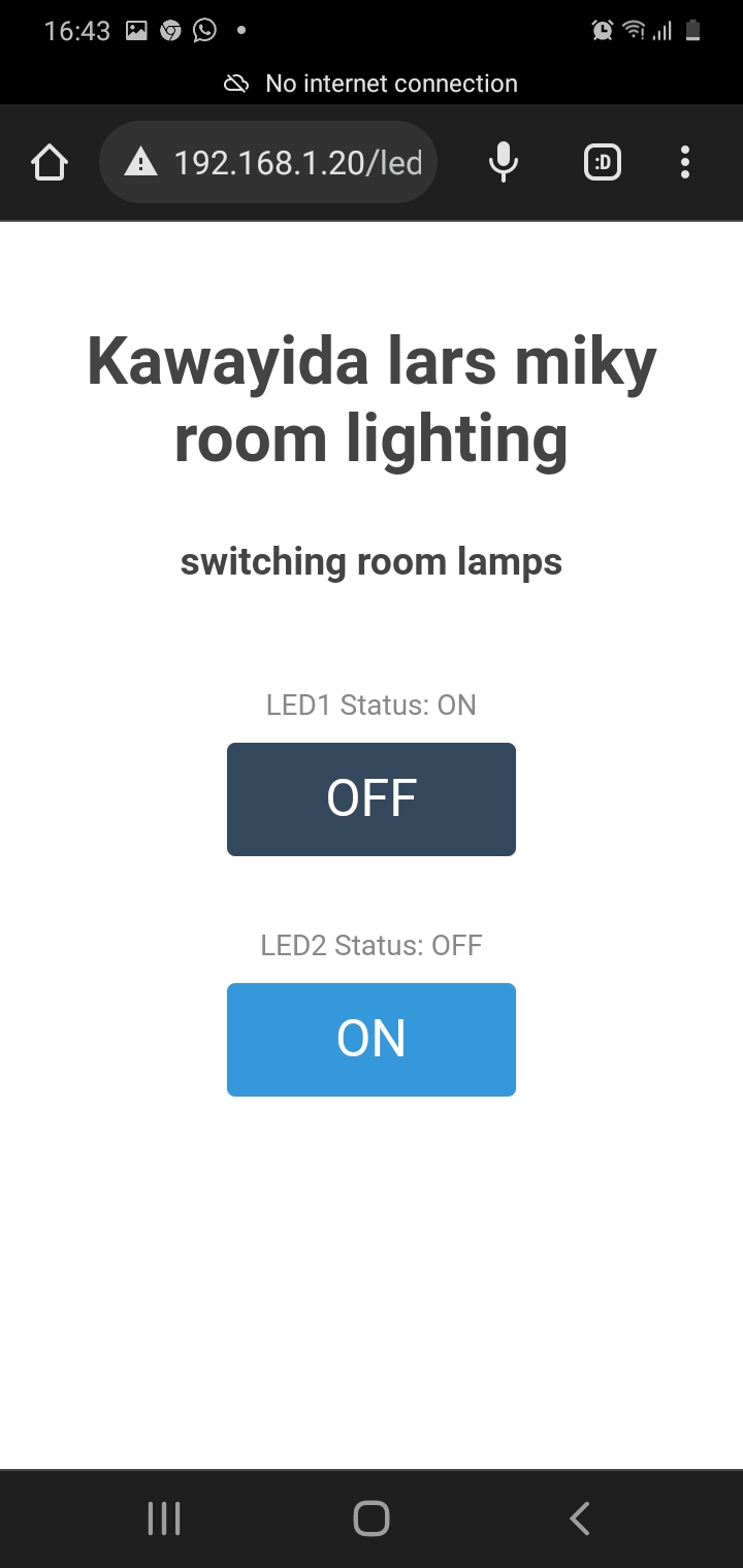
here you folow the video of more detail of how i used esp as web server to switvh my room ligthings