Embedded microcontroller interfacing and programming
System integration and packaging
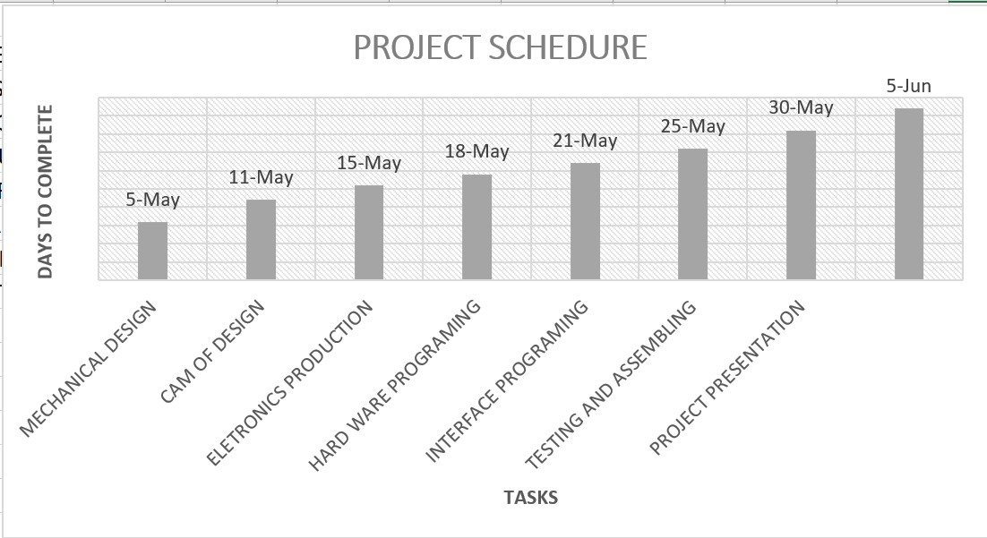
tasks
system design.
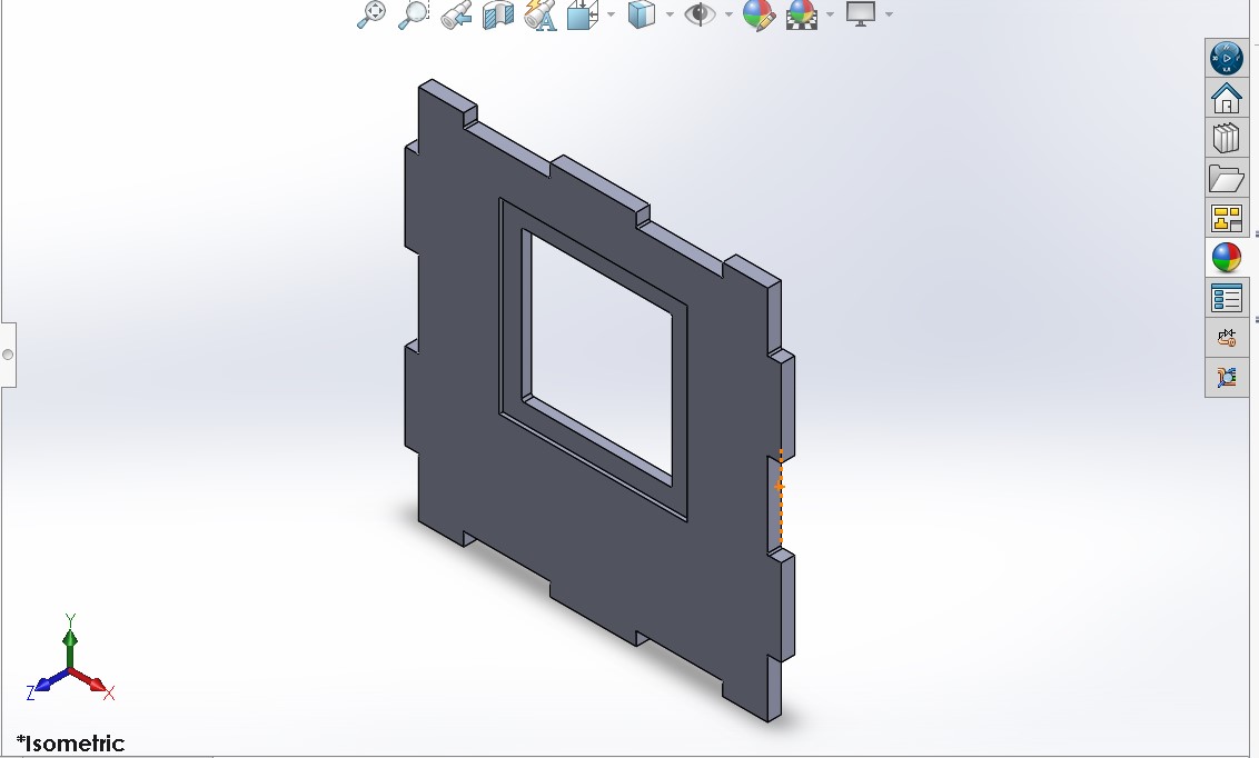
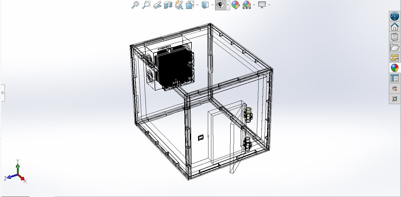
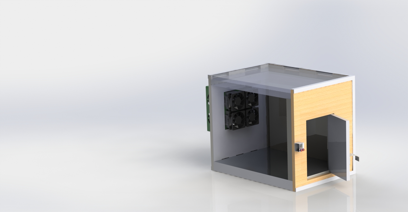
Full assembly of the 3D system DESIGN
cooler System design and assembly
THERMAL SYSTEM
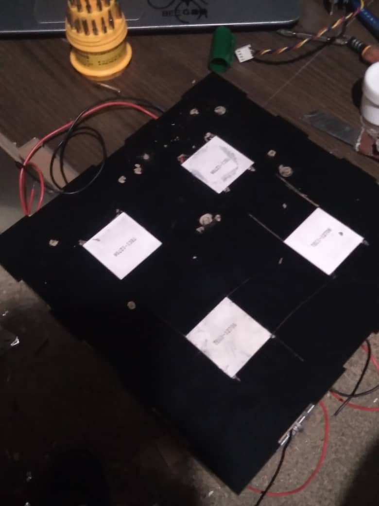
Thermal system configuration On my system.
core device of my cooling system (I used 4 pieces)
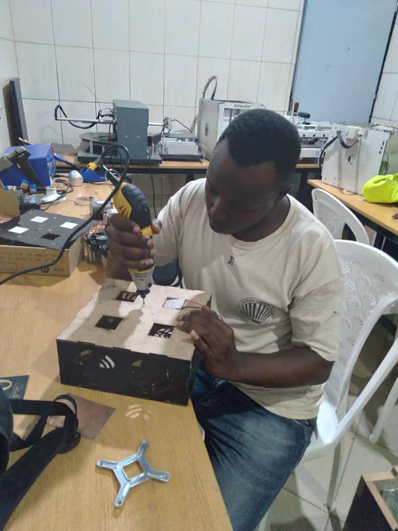
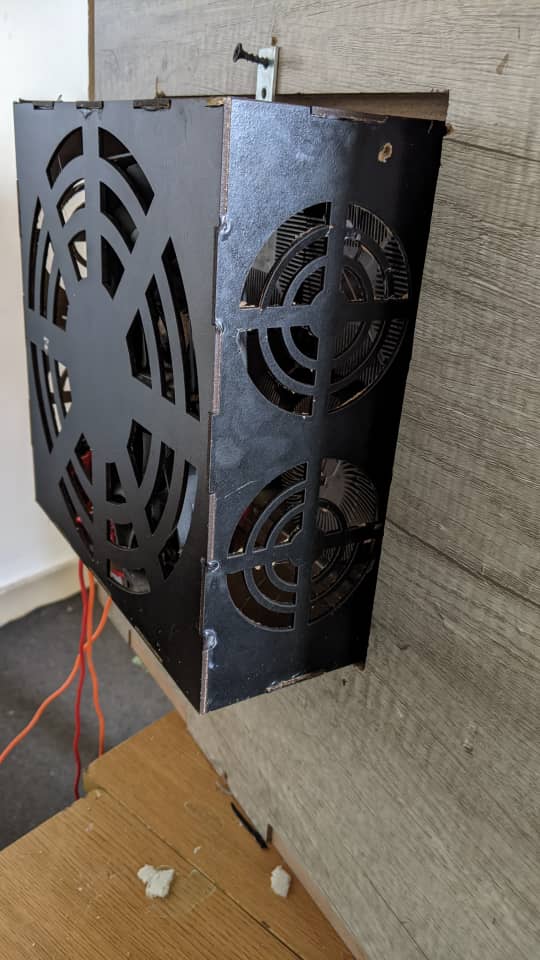
Assembly of cooling systen for my cold room.
implemantation of cooling system
Assembly of cooling systen for my cold room.
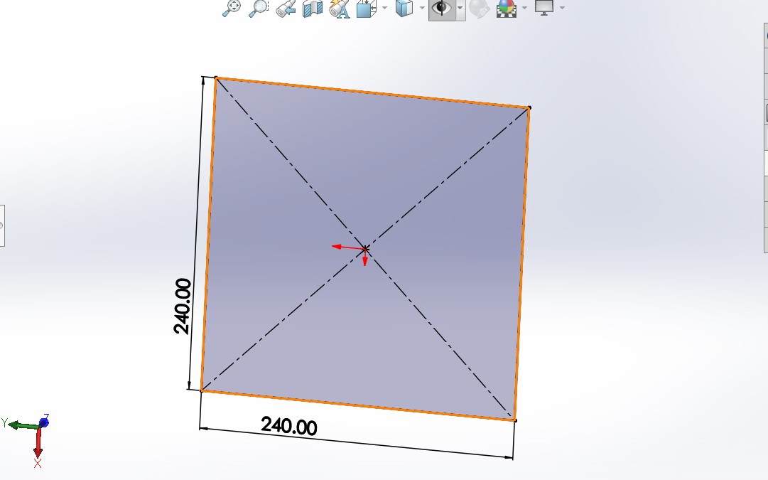
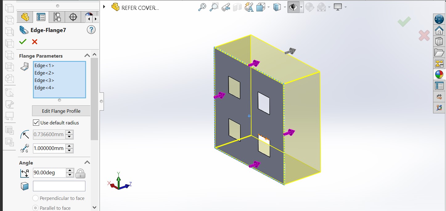
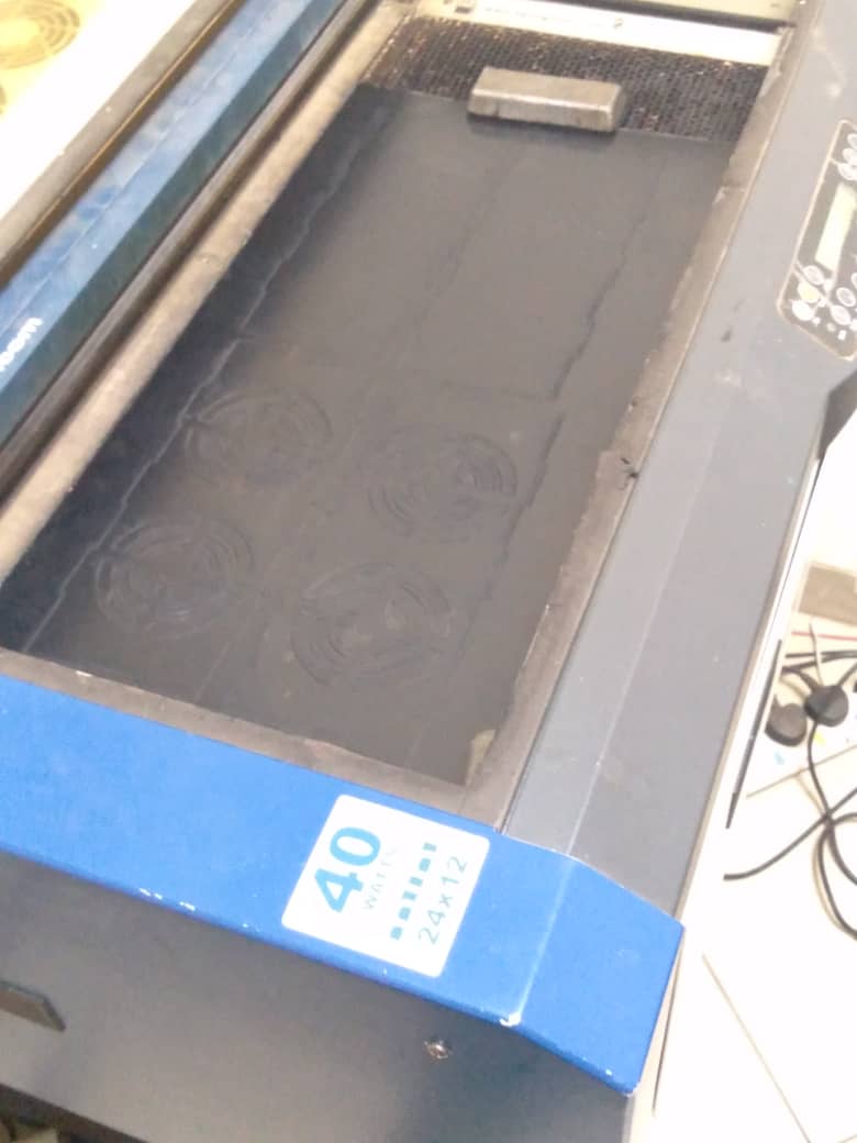
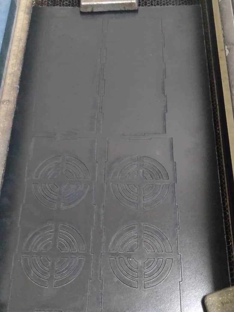
laser cuter of cooler housing
laser cutting
laser cuting,
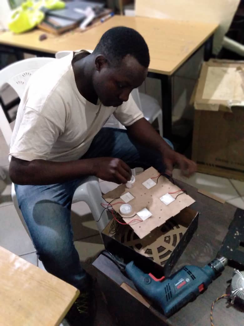
cooler assembling
peltier devices assembly of my cooling system (I used 4 pieces)
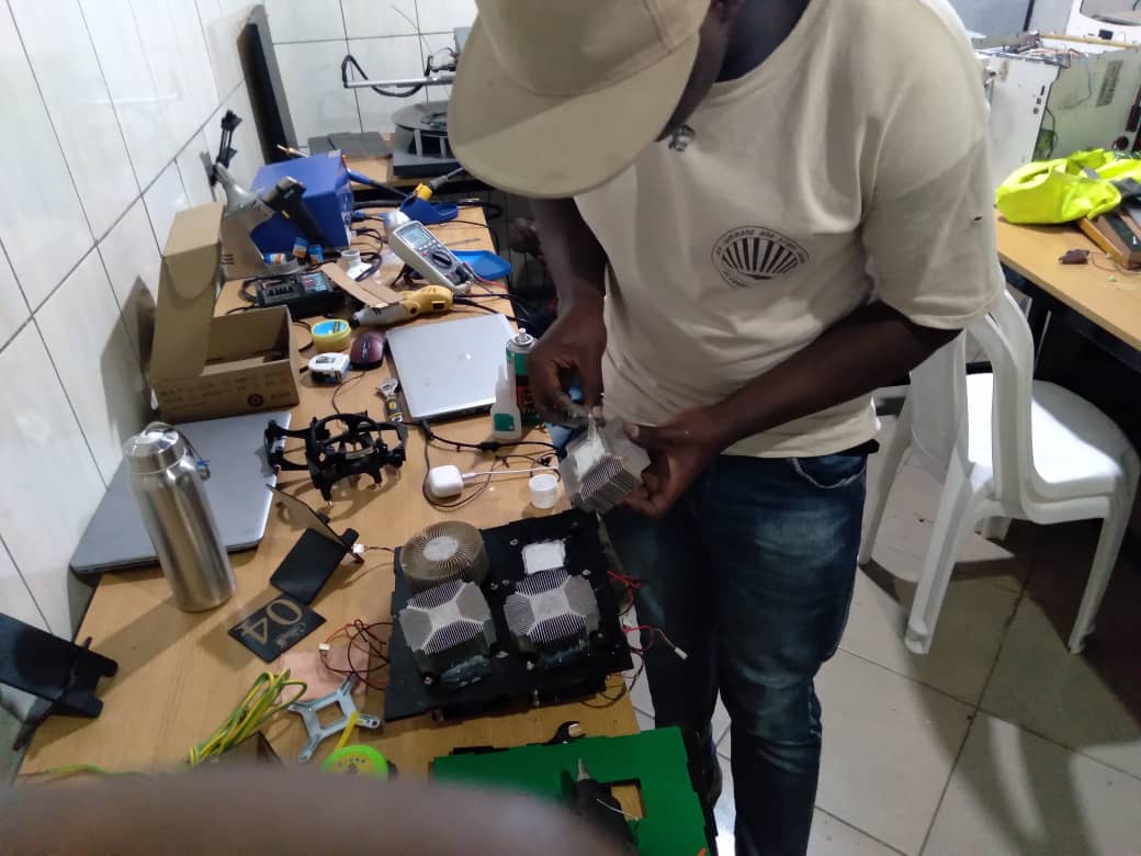
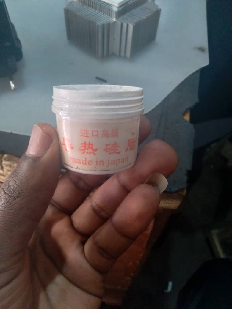
heat sink attachment on peltier plate with thermal paste.
this is thermal paste to easier the heat transfer between peltier plate and heatsink.
how cooling system is attached on cold room
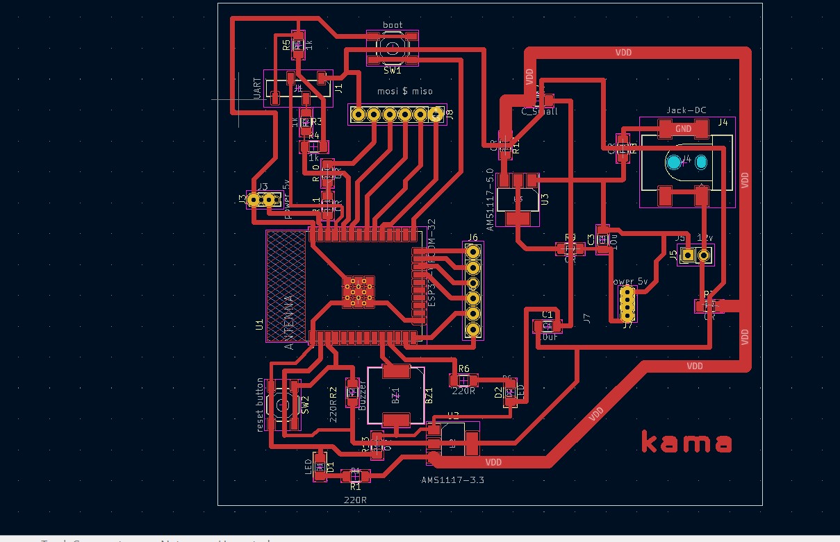
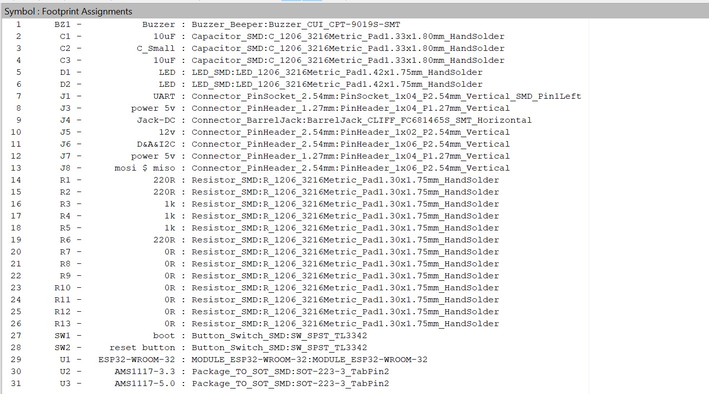
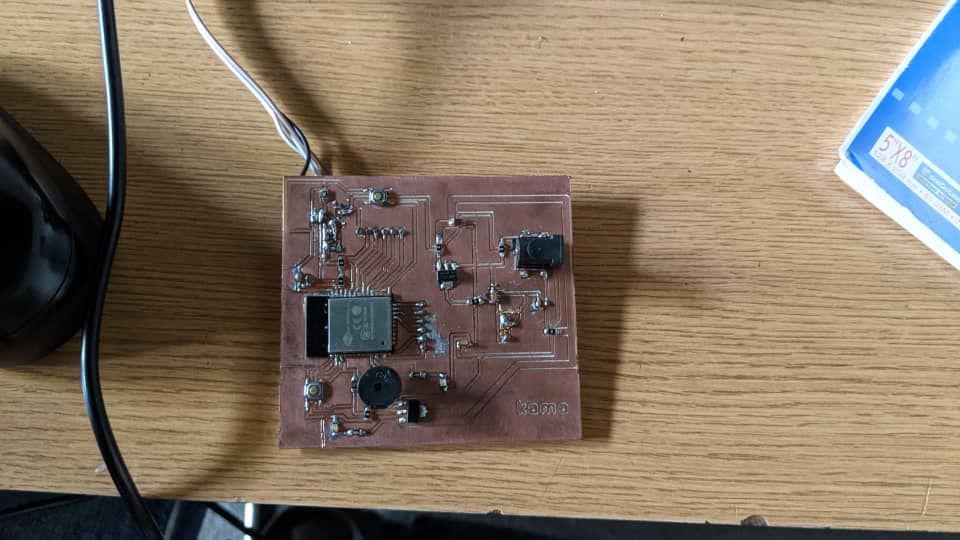
Electronics design and production
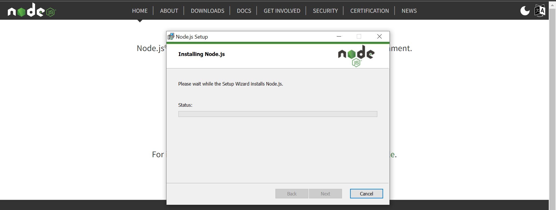
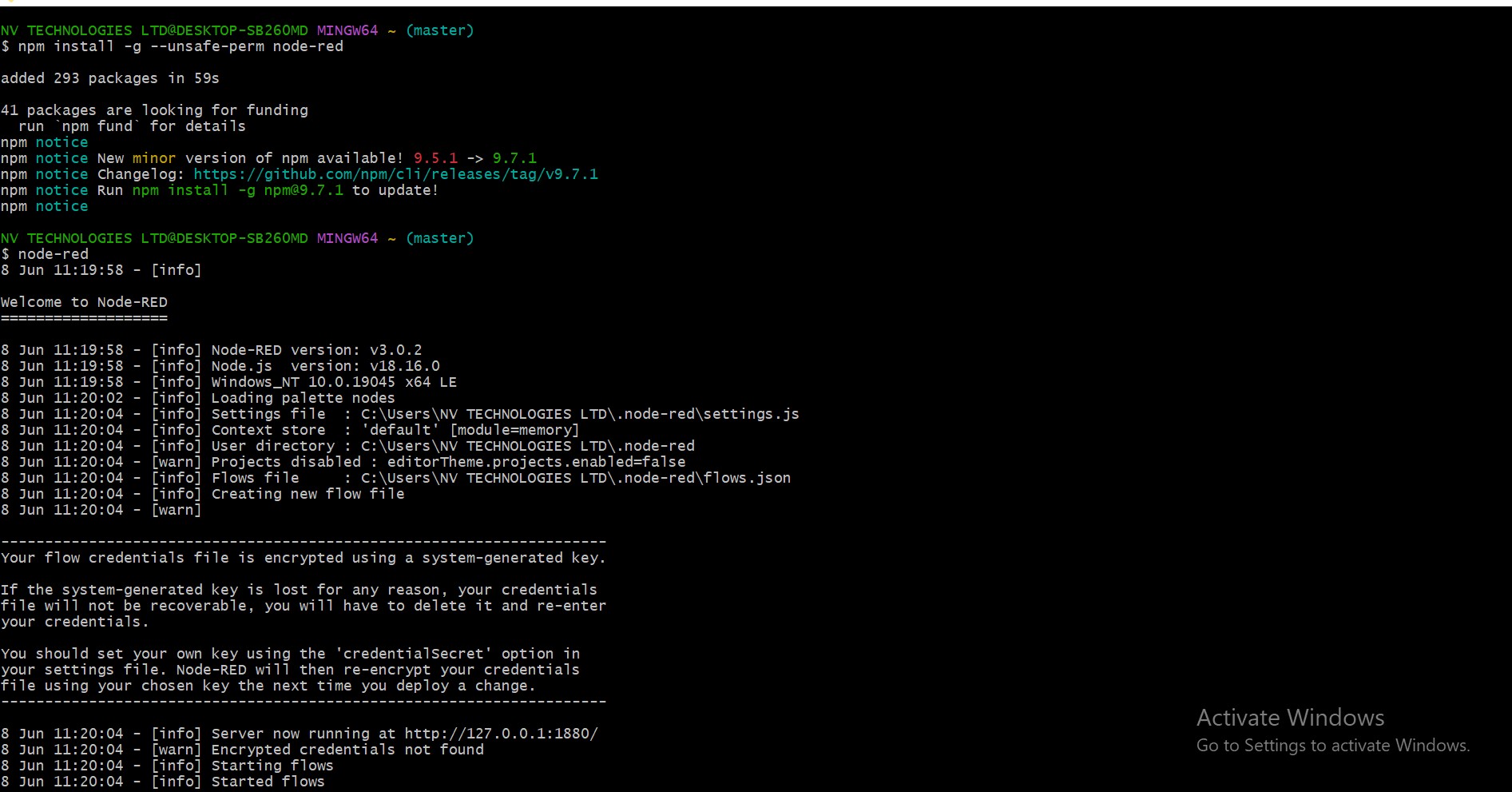
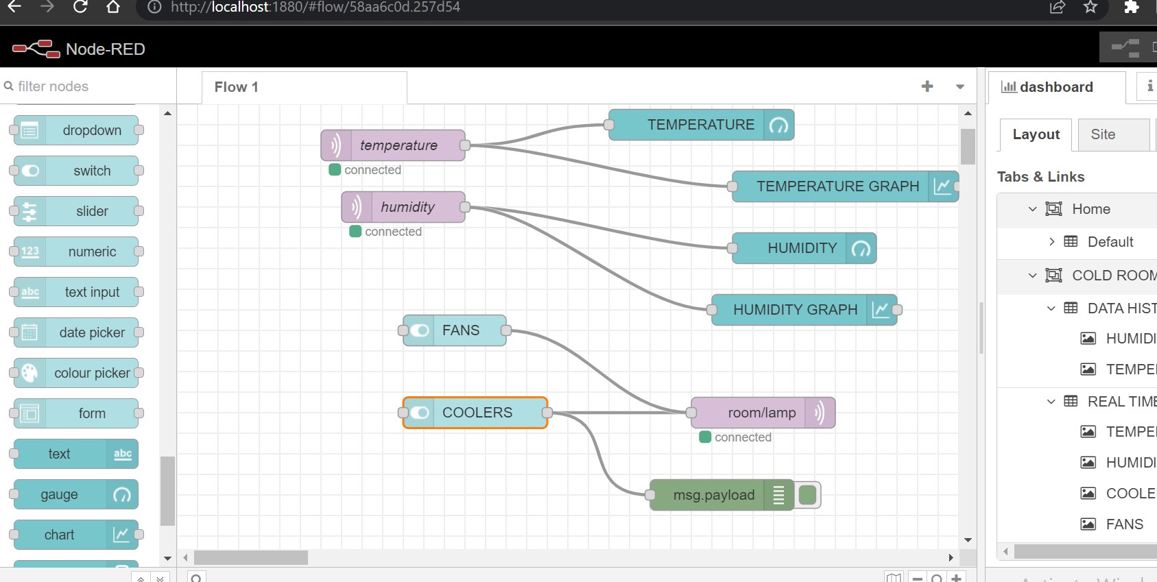
Embedded microcontroller interfacing and programming
CODE FOR INTERFACE AND CONTROL OF COLD ROOM
 #include
  #include
  #include "DHT.h"
  #include

  // Uncomment one of the lines bellow for whatever DHT sensor type you're using!
  #define DHTTYPE DHT11   // DHT 11
  //#define DHTTYPE DHT21   // DHT 21 (AM2301)
  //#define DHTTYPE DHT22   // DHT 22  (AM2302), AM2321


  LCD_I2C lcd(0x27, 16, 2);
  // Change the credentials below, so your ESP8266 connects to your router
  const char* ssid = "Kama";
  const char* password = "12345678";

  // Change the variable to your Raspberry Pi IP address, so it connects to your MQTT broker
  const char* mqtt_server = "192.168.204.250";

  // Initializes the espClient. You should change the espClient name if you have multiple ESPs running in your home automation system
  WiFiClient espClient;
  PubSubClient client(espClient);

  // DHT Sensor - GPIO 5 = D1 on ESP-12E NodeMCU board
  const int DHTPin = 15;

  // Lamp - LED - GPIO 4 = D2 on ESP-12E NodeMCU board
  const int lamp = 18;
  const int lamp1 = 19;
  const int lamp2 = 15;

  // Initialize DHT sensor.
  DHT dht(DHTPin, DHTTYPE);

  // Timers auxiliar variables
  long now = millis();
  long lastMeasure = 0;

  // Don't change the function below. This functions connects your ESP8266 to your router
  void setup_wifi() {

    delay(10);
    // We start by connecting to a WiFi network
    Serial.println();
    Serial.print("Connecting to ");
    Serial.println(ssid);
    WiFi.begin(ssid, password);
    while (WiFi.status() != WL_CONNECTED) {
      delay(500);
      Serial.print(".");
    }
    Serial.println("");
    Serial.print("WiFi connected - ESP IP address: ");
    Serial.println(WiFi.localIP());
  }

  // This functions is executed when some device publishes a message to a topic that your ESP8266 is subscribed to
  // Change the function below to add logic to your program, so when a device publishes a message to a topic that
  // your ESP8266 is subscribed you can actually do something
  void callback(String topic, byte* message, unsigned int length) {
    Serial.print("Message arrived on topic: ");
    Serial.print(topic);
    Serial.print(". Message: ");
    String messageTemp;

    for (int i = 0; i < length; i++) {
      Serial.print((char)message[i]);
      messageTemp += (char)message[i];
    }
    Serial.println();

    // Feel free to add more if statements to control more GPIOs with MQTT

    // If a message is received on the topic room/lamp, you check if the message is either on or off. Turns the lamp GPIO according to the message
    if(topic=="room/lamp"){
        Serial.print("Changing Room lamp to ");
        if(messageTemp == "on"){
          digitalWrite(lamp, LOW);
          Serial.print("On");
        }
        else if(messageTemp == "off"){
          digitalWrite(lamp, HIGH);
          Serial.print("Off");
        }
          if(messageTemp == "on1"){
          digitalWrite(lamp1, LOW);
          Serial.print("On");
        }
        else if(messageTemp == "off1"){
          digitalWrite(lamp1, HIGH);
          Serial.print("Off");
        }
          if(messageTemp == "on2"){
          digitalWrite(lamp2, LOW);
          Serial.print("On");
        }
        else if(messageTemp == "off2"){
          digitalWrite(lamp2, HIGH);
          Serial.print("Off");
        }
    }
    Serial.println();
  }

  // This functions reconnects your ESP8266 to your MQTT broker
  // Change the function below if you want to subscribe to more topics with your ESP8266
  void reconnect() {
    // Loop until we're reconnected
    while (!client.connected()) {
      Serial.print("Attempting MQTT connection...");
      // Attempt to connect
      /*
       YOU MIGHT NEED TO CHANGE THIS LINE, IF YOU'RE HAVING PROBLEMS WITH MQTT MULTIPLE CONNECTIONS
       To change the ESP device ID, you will have to give a new name to the ESP8266.
       Here's how it looks:
         if (client.connect("ESP8266Client")) {
       You can do it like this:
         if (client.connect("ESP1_Office")) {
       Then, for the other ESP:
         if (client.connect("ESP2_Garage")) {
        That should solve your MQTT multiple connections problem
      */
      if (client.connect("ESP8266Client")) {
        Serial.println("connected");
        // Subscribe or resubscribe to a topic
        // You can subscribe to more topics (to control more LEDs in this example)
        client.subscribe("room/lamp");
      } else {
        Serial.print("failed, rc=");
        Serial.print(client.state());
        Serial.println(" try again in 5 seconds");
        // Wait 5 seconds before retrying
        delay(5000);
      }
    }
  }

  // The setup function sets your ESP GPIOs to Outputs, starts the serial communication at a baud rate of 115200
  // Sets your mqtt broker and sets the callback function
  // The callback function is what receives messages and actually controls the LEDs
  void setup() {
      lcd. begin ();
       lcd. backlight ();
    pinMode(lamp, OUTPUT);
    pinMode(lamp1, OUTPUT);
    pinMode(lamp2, OUTPUT);
    dht.begin();
     digitalWrite(lamp, HIGH);
      digitalWrite(lamp1, HIGH);
    Serial.begin(115200);
    setup_wifi();
    client.setServer(mqtt_server, 1883);
    client.setCallback(callback);

  }

  // For this project, you don't need to change anything in the loop function. Basically it ensures that you ESP is connected to your broker
  void loop() {

    if (!client.connected()) {
      reconnect();
    }
    if(!client.loop())
      client.connect("ESP8266Client");

    now = millis();
    // Publishes new temperature and humidity every 10 seconds
    if (now - lastMeasure > 10000) {
      lastMeasure = now;
      // Sensor readings may also be up to 2 seconds 'old' (its a very slow sensor)
      float h = dht.readHumidity();
      // Read temperature as Celsius (the default)
      float t = dht.readTemperature();
      // Read temperature as Fahrenheit (isFahrenheit = true)
      float f = dht.readTemperature(true);

      // Check if any reads failed and exit early (to try again).
      if (isnan(h) || isnan(t) || isnan(f)) {
        Serial.println("Failed to read from DHT sensor!");
        return;
      }

      // Computes temperature values in Celsius
      float hic = dht.computeHeatIndex(t, h, false);
      static char temperatureTemp[7];
      dtostrf(hic, 6, 2, temperatureTemp);

      // Uncomment to compute temperature values in Fahrenheit
      // float hif = dht.computeHeatIndex(f, h);
      // static char temperatureTemp[7];
      // dtostrf(hif, 6, 2, temperatureTemp);

      static char humidityTemp[7];
      dtostrf(h, 6, 2, humidityTemp);
      static char heatindex[7];
      dtostrf(hic, 6, 2, heatindex);

      // Publishes Temperature and Humidity values
      client.publish("room/temperature", temperatureTemp);
      client.publish("room/humidity", humidityTemp);
      //client.publish("room/heat", heatindex);
      lcd.setCursor(0,0);
      lcd.print("hum");
      lcd.setCursor(5,0);
      lcd.print(h);
      lcd.setCursor(0,1);
      lcd.print("temp");
      lcd.setCursor(5,1);
      lcd.print(t);
      Serial.print("Humidity: ");
      Serial.print(h);
      Serial.print(" %\t Temperature: ");
      Serial.print(t);
      Serial.print(" *C ");
      Serial.print(f);
      Serial.print(" *F\t Heat index: ");
      Serial.print(hic);
      Serial.println(" *C ");
      // Serial.print(hif);
      // Serial.println(" *F");
    }
  }
System integration and packaging
my system integration concerns with relay and pcb embeded with esp32 for controlling the cold room remotely.
project assembling final model.
this pictures mationed above show the assembling of the system with is insullation
bellow you can read my project fuctionalities ,scope of my project and how my project will be evaluatede,currently all system done are working perfectly like cooling system , and control system with nodred interface.
what does it do
The remote-controlled cold room I'm working on will provide a controlled environment for keeping perishable food items, like fruits and vegetables, at a temperature between 25 and 5 degrees Celsius. At temperatures ranging from 5 to –20 degrees Celsius, it also offers storage for meats and vaccines. By allowing for exact temperature control, this system creates the ideal environment for maintaining the quality and security of the stored goods.
Who has done what beforehand
many researchers and manufacteres have done the same concept of using the peltier to provide the coldness in specif room regarding to the degree of coldness required.
through that allow me to presante this coleague called "Silvio Pietro Monticelli"who done "Gene Freezz which is the prototype of a portable cooler, with an embedded freezer, to support DANA barcoding activities in the field."
here you can find more detail on the project even if he did'nt controlled the cold room remotely.click here:References
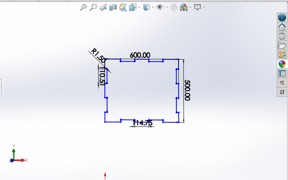
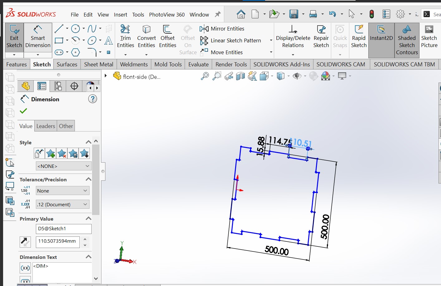
What will you design
the design of my project will concerns with mechanical structure design and eletronic circuit design and cooling system design
The materials and components used are listed below including loacation & price and
MATERIALS USED
No
ITEM NAMES
SPECIFICATIONS
QUANTITY
UNIT PRICE(Rwf)
TOTAL PRICE(Rwf)
location source of material
1.
Microcontroller
ESP-wrom-32
1
15000
15000
2.
DHT11 SENSOR
15.5mm x 12mm x 5.5mm.
1
8000
8000
3.
FOUR CHANEL RELAY
DC 5V
4
4500
18000
4.
OLED
96'
1
3500
3500
5.
FANS
12V
8
5000
40000
6.
POWER Supply
12V ,30A
1
25000
25000
7.
Voltage Regulator
5V AMS1117
1
500
500
8.
HEAT SINK
20×4
8
5000
40000
9.
Copper PCB
single side 7x10cm
1
2000
2000
10.
Jumper Wires and others
Male,Female
1
6000
6000
11.
Acrylic
40x40x3
1
80000
80000
12.
PELTIA COOLER
12V 5A
4
5000
20000
13.
Thermal conductor oil
Super conductor greese
1 cap
4000
4000
14.
Capacitors
Small
3
1000
3000
15.
LED
Small
3
1000
3000
16.
Button_Switch
Small
3
1000
3000
17.
Buzzer
5V
1
500
500
18.
Voltage Regulator IC
3V
1
500
500
19.
polystelen insullator
30mm of thicknes
1 sheet
30000
30000
20.
Aluminium sheet
0.25 of thicknes
1 sheet
6000
6000
TOTAL
N/A
29
154,800
162,800
What parts and systems will be made and processes which will be used.
my system is contains two parts
MECHANICAL PART
,
ELETRONIC PART
The process used for mechanical part
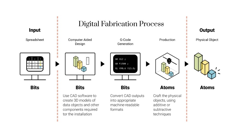
AS we are doing digital fabrication and how to make any thing almost , i started with cad which is computer ided design of my structure and then genarate g-code of my design in CAM process which is computer aide manufucturing .
Process used for eletronics
eletronic part of my project also concerns with CAD and CAM the same with mechanical but the soft ware used and machine used for manufacturing are difference.there for pcb design was designed in kicard and printed with roland machine.
What questions need to be answered?
the quastion to be answered are how can we controll the cold rooms remotetly to reduce the post haverst loss?
and What role does effective crop preservation play in reducing post-harvest losses and conserving perishable food in remote-controlled cool rooms?
both quastion will be answered by this paragraph of In order to reduce
post-harvest losses and preserve perishable food in remotely controlled cool rooms,
effective crop preservation is essential. It is simpler to guarantee ideal storage conditions
for crops by putting advanced monitoring and control systems in place, like the culminating project in the Fab Academy program here in Rwanda. Real-time temperature and humidity monitoring made possible by this technology enables prompt adjustments to maintain perfect conditions. Perishable food's shelf life can be increased by lowering temperature variations and environmental control, which also lowers spoilage and
post-harvest losses and ultimately promotes sustainability and food security.
one of global challenge to be answered.
How will it be evaluated: here we there is a scope of my project which will guide in evaluation process.
my project will reflect on fab academy courses such us
Input/output devices: temperature sensors, LCDs, Peltier devices, case fans
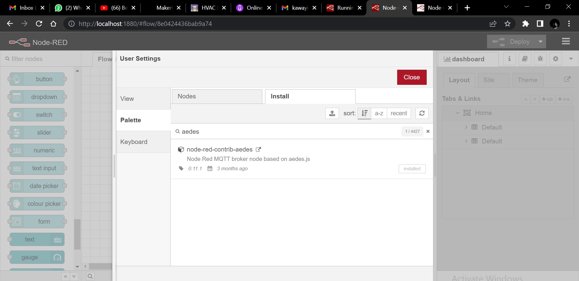
Networking and communications: control board ↔ users ↔ cooler board;
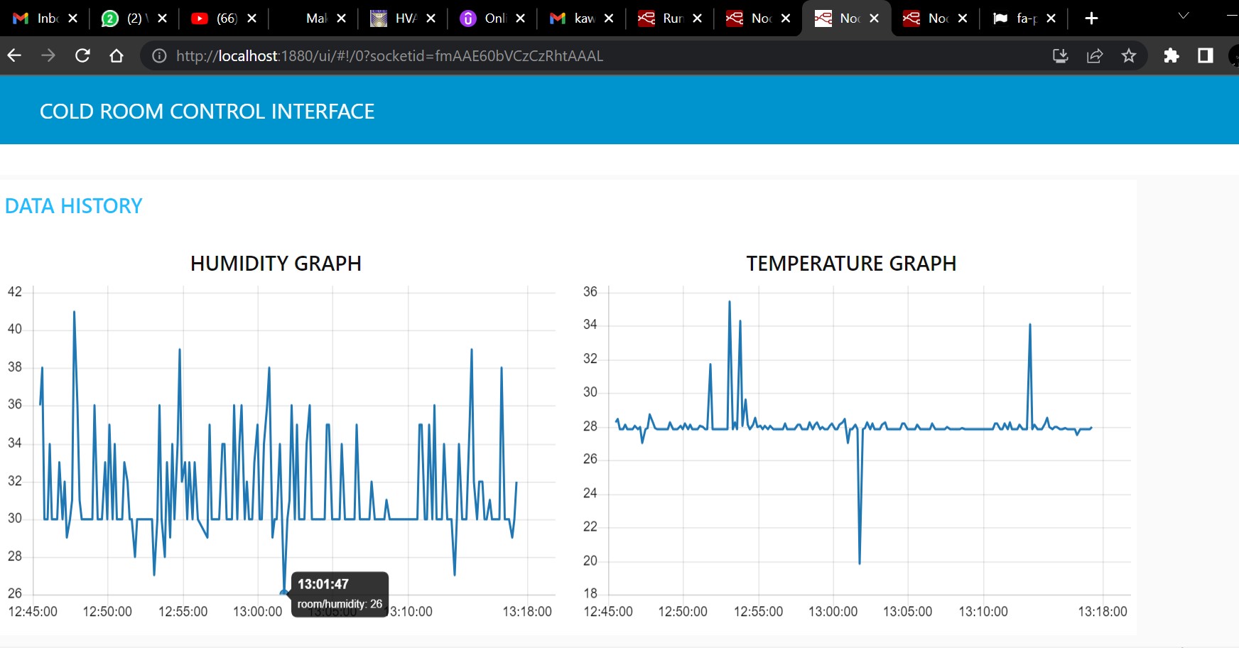
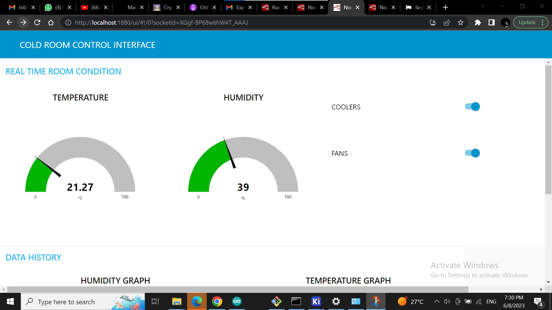
Interfaces and application programming: temperature application interface.
Regarding to the course and to pic covered in fab academy program my project scope are
Modular design which will provide the storage area
The system reacts to ambient ambient temperature variations, according to growth cycle (hot, warm, fresh, cold):
absolute and differential temperature readings → moves away from locol to grobal whenever the internet is available .
The system will indicate to ambient moisture (relative humidity) variations:
The system records the time spent in the same pot. Sends alert after a set period;
The system can perform ambient check over a period of time
the system will have the capability of controlling the actuator remotly and monutering remotely.
honestly i will delived the following thangible and intergible asset created and procured by me for the sucess of the project
Modular wooden stand with height modules and cables rod
Electronics
Multiple set of sensors: moisture and temperature,
Electronic board for comparing input signals (sensors) and reference data (database) and triggering actions: output signals to funs switches (peltier plate, and fun),

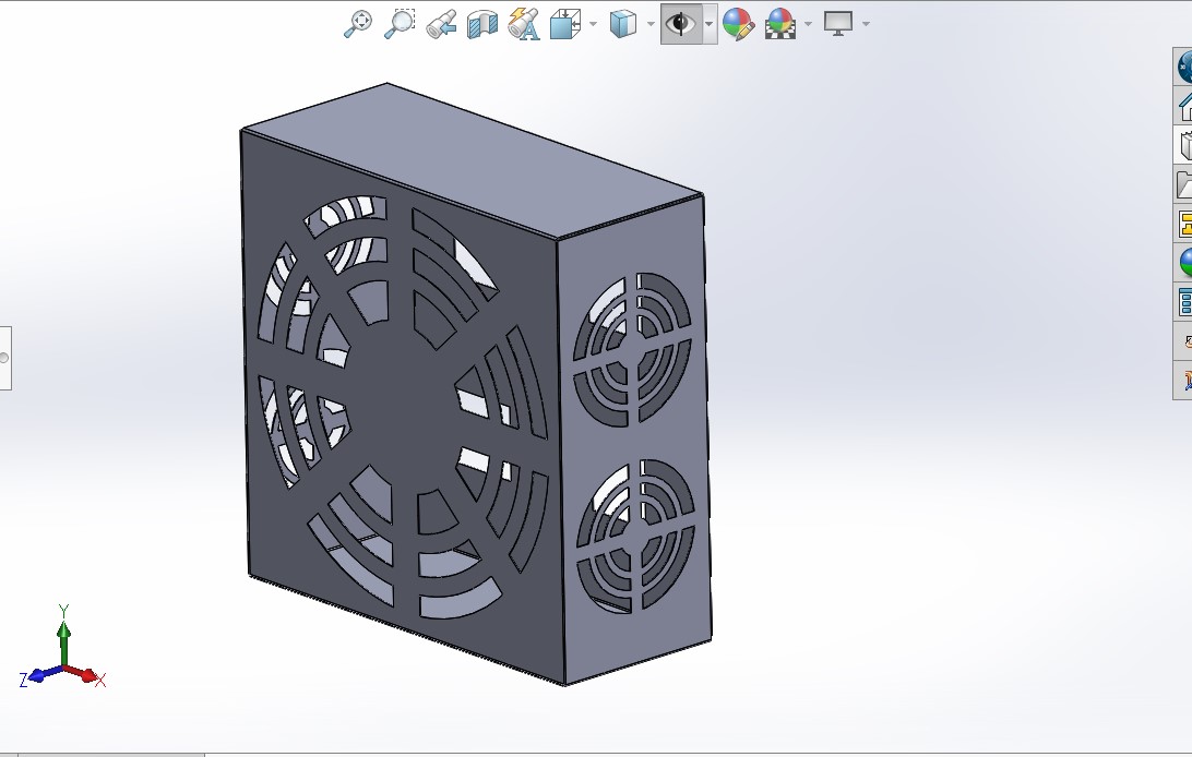
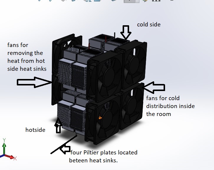 Thermal system configuration On my system.
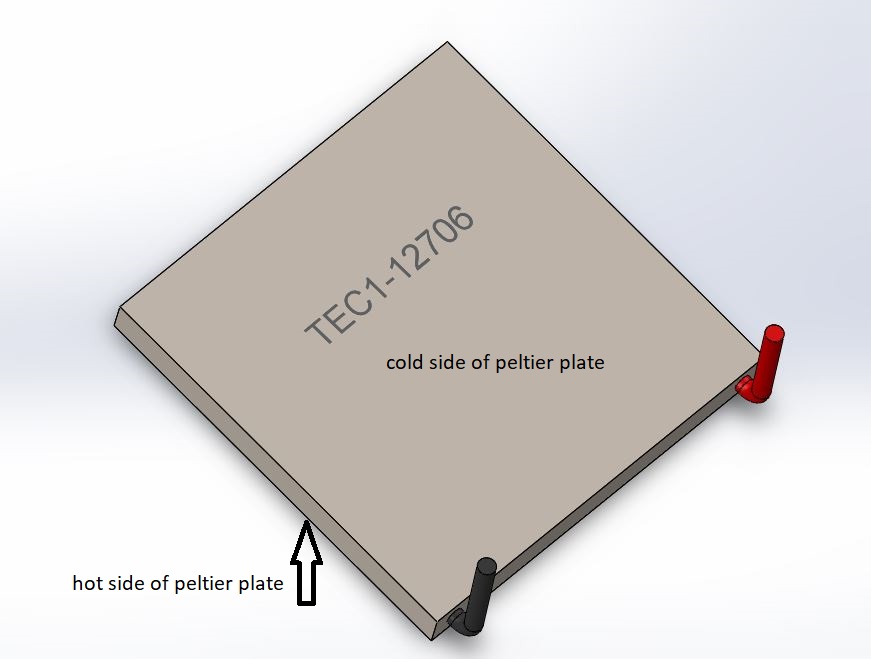 core device of my cooling system (I used 4 pieces)
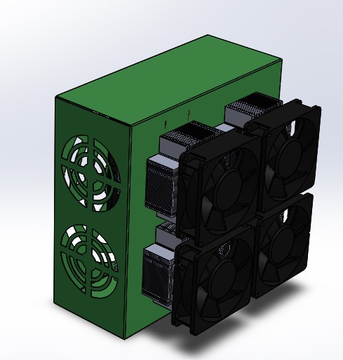 Assembly of cooling systen for my cold room.
 laser cutting
 laser cuting,