Out put devices
Assignment
Group-Assigniment
- Probe an input device(s)'s analog and digital signals
- Document your work on the group work page and reflect on your individual page what you learned
here there is more description on work on this group web page:Group work description is on here
Individual assignment
- Probe an input device(s)'s analog and digital signals
- Document your work on the group work page and reflect on your individual page what you learned
Individual assignment
Measure something: add a sensor to a microcontroller board that you have designed and read it
Table of Content
- designed dev board
- Confguration and integration of sensor on my designed board
DESIGN PROCEDURE OF MY DESIGN of my development board
p class="text-start">DESIGN PROCEDURE OF MY DESIGN of my development board and circuit programmer
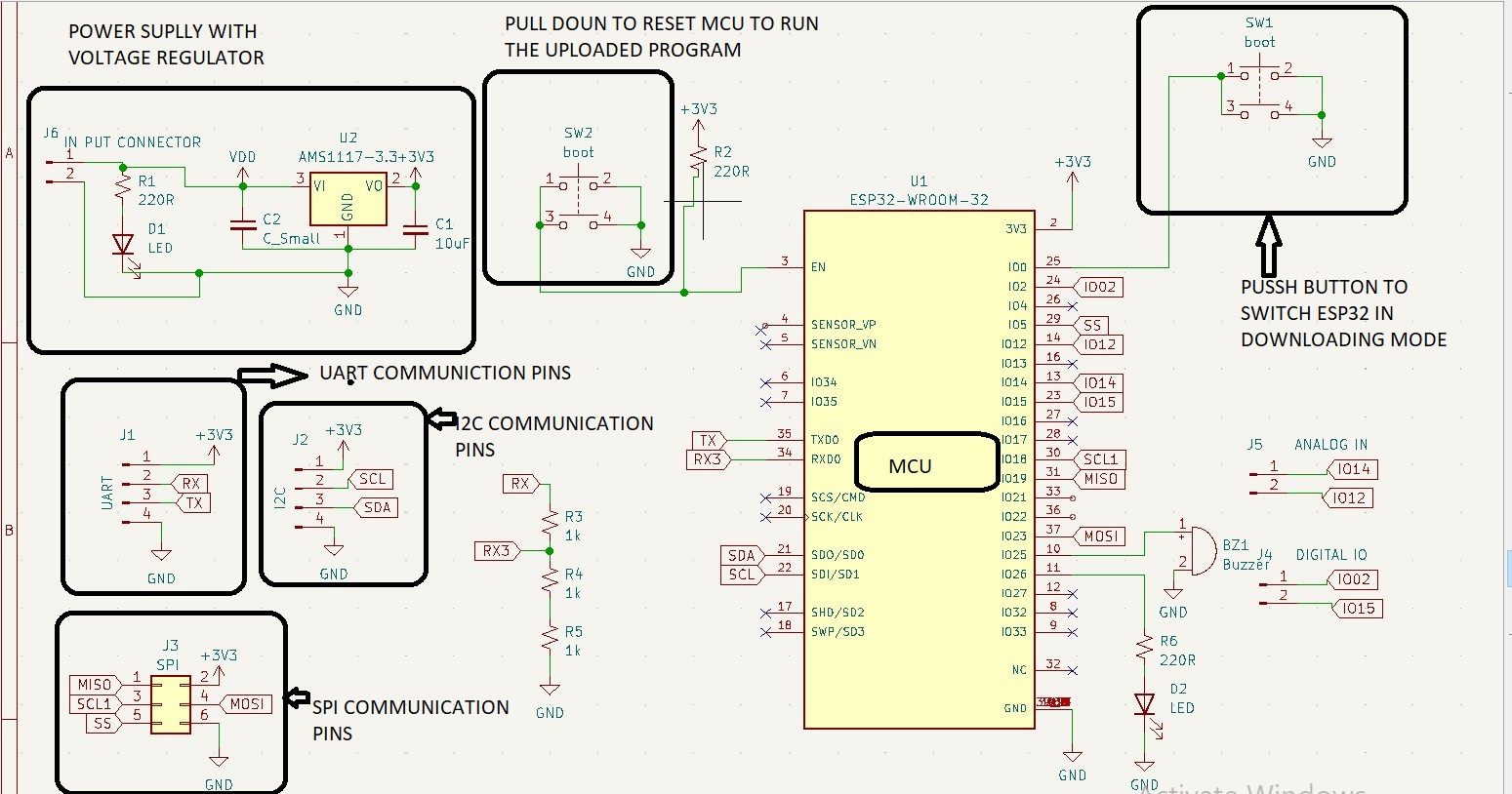
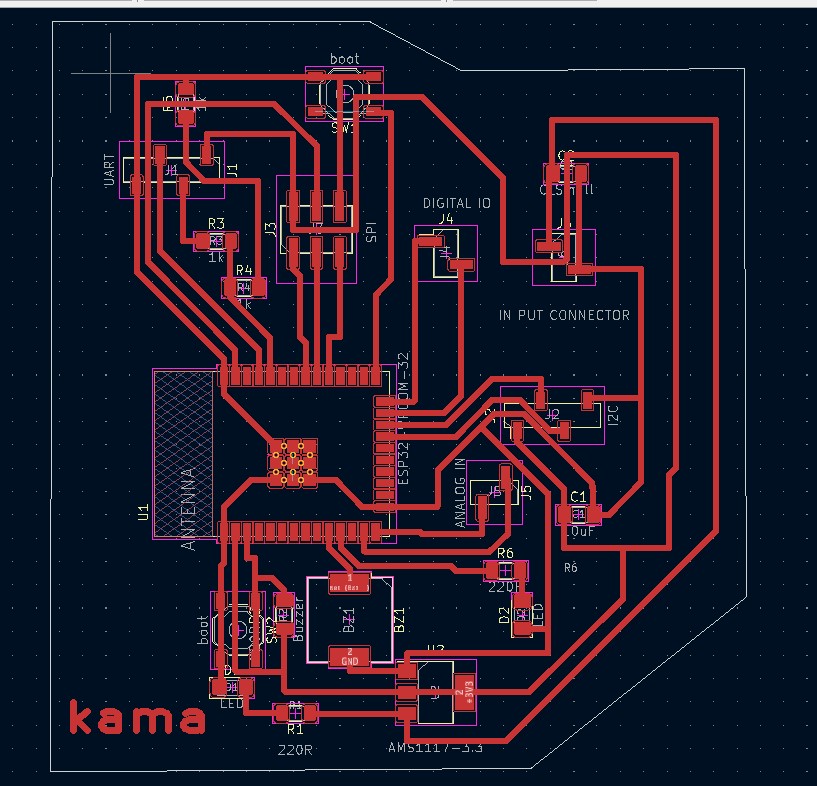
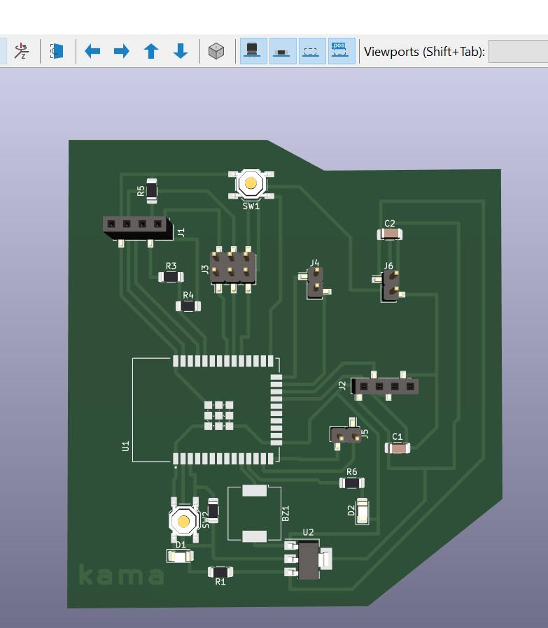
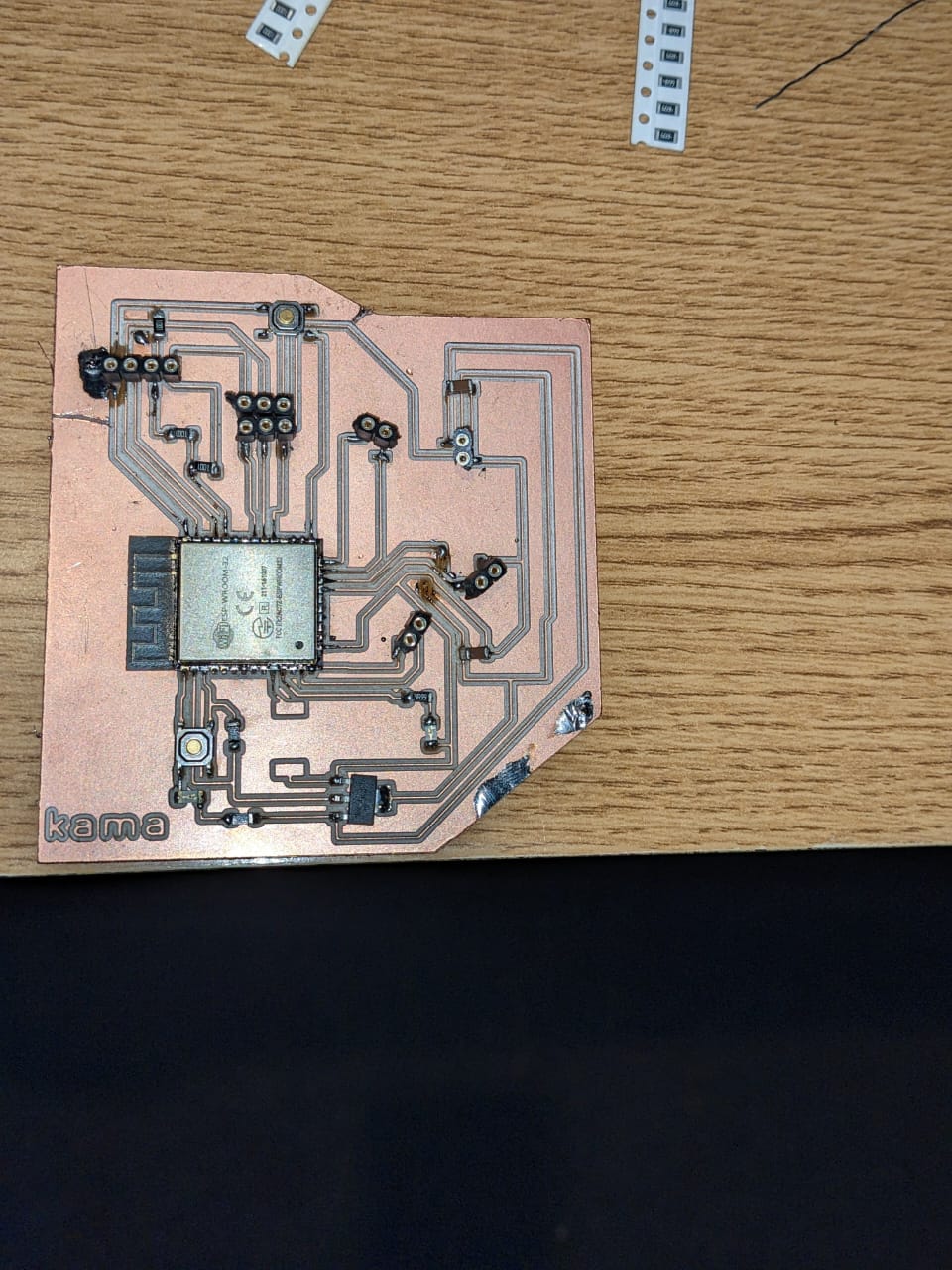
design procedure of my pcb board
description circuit bord
here i would like to use esp32 microcontroller on my development board in order to interact with my out put (servor motor).there for my programmer designed before will convert the USB signal from your PC into UART communication so that i can program the ESP32 on the development board. This will allow me to send code and configuration information from your PC to the ESP32 using the chosen communication protocol of the microcontroller. The programmer will act as an interface between your PC and the ESP32, ensuring that the data is properly formatted and transmitted for successful programming.
Here you can find the procedure i used to design my dev-b
Design procedure of my programer
List of components
- esp32 MCU
- AMS1117 voltage regulator
- USB connector
- LED
- Capacitor (10uF)
- Resistor (optional)
my development board components list and thier foot prints
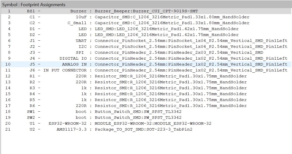
- esp32 MCU
- AMS1117 voltage regulator
- USB connector
- LED
- Capacitor (10uF)
- Resistor (optional)
List of components
DHT11 Sensor DATA SHEET
DHT11 can measure temperature from 0°C to 50°C with a ±2.0°C accuracy, and humidity from 20 to 80% with a 5% accuracy.

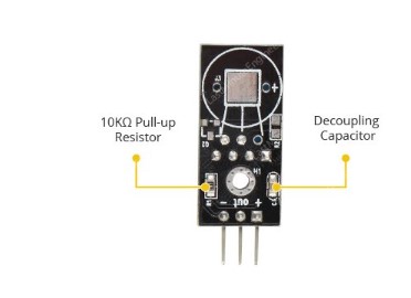
AS mentioned in data sheet the DHT11 sensoe has a sampling rate of 1Hz, which means it can provide new data once every second.and also DHT11 sensors typically require an external 10K pull-up resistor on the output pin for proper communication between the sensor and the Arduino. However, because the module already includes a pull-up resistor, you do not need to add one. The module also includes a decoupling capacitor for filtering power supply noise.
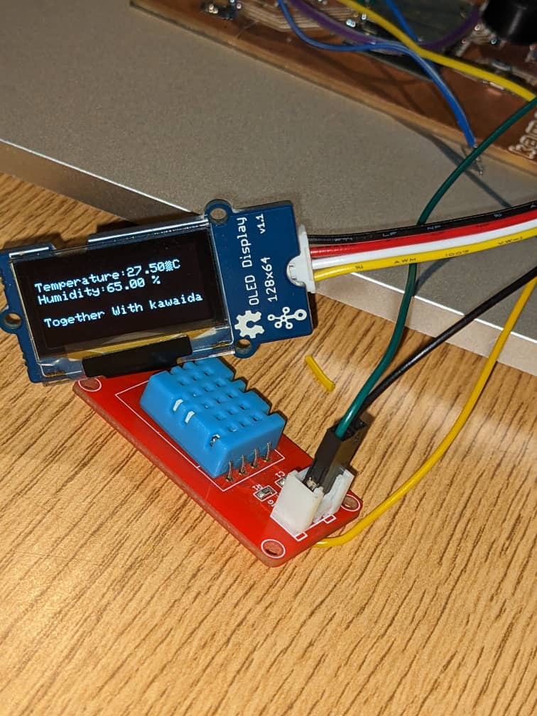
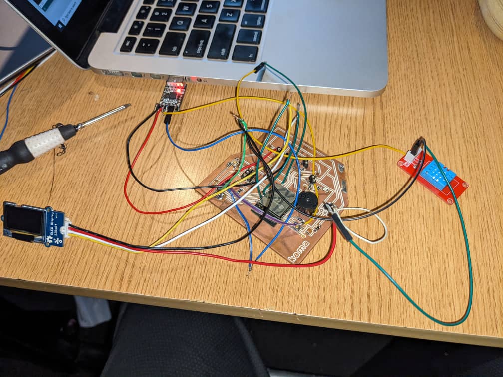
The DHT11 module is relatively simple to connect. There are only three pins.
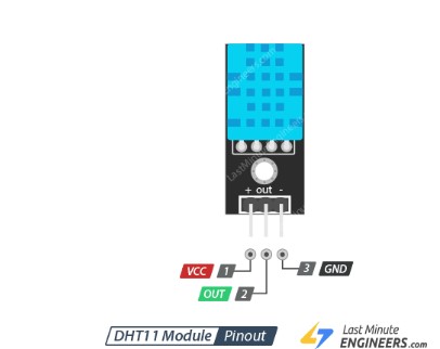
connection
programing section
the first things is to install libraly in arduino ide becouse The DHT sensors has their own proprietary single-wire data transfer protocol. This protocol requires precise timing. We don’t have to worry too much about this, though, because we’ll be using the DHTlib library, which handles almost everything.here you there is the link used to get library:libraly
program
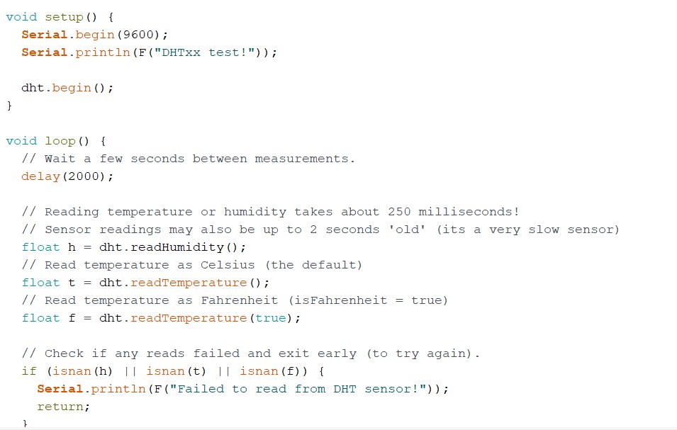
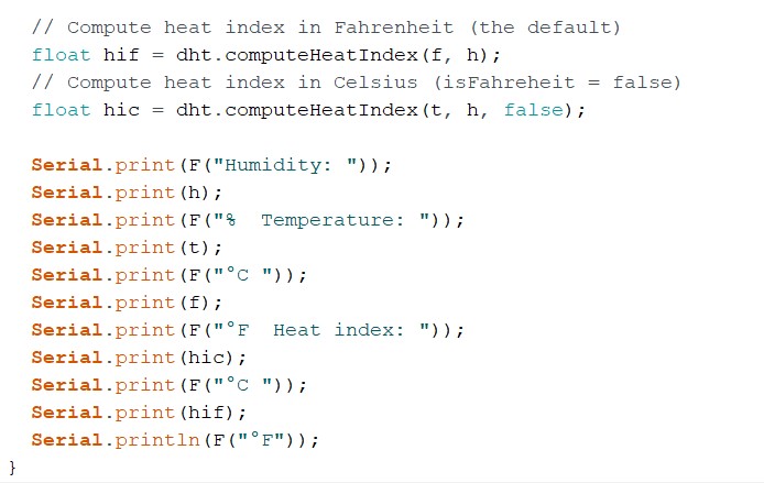
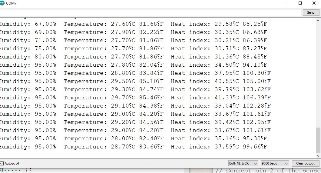
sensor readings