My FINAL PROJECT "Smart cold room"
Project Background
My idea of final project is to design ,fabricate and code the control monitoring system of COLD rooms In addition this coldroom will composed with software part and hardware part for the aim of creating artificial environment in order to conserve the perishable food.
Problem statement
In recent years, various United Nations reports have stressed the growing constraint of food supply for Earth's growing human population. most of fruits and other perishable food ,


Project Sketch
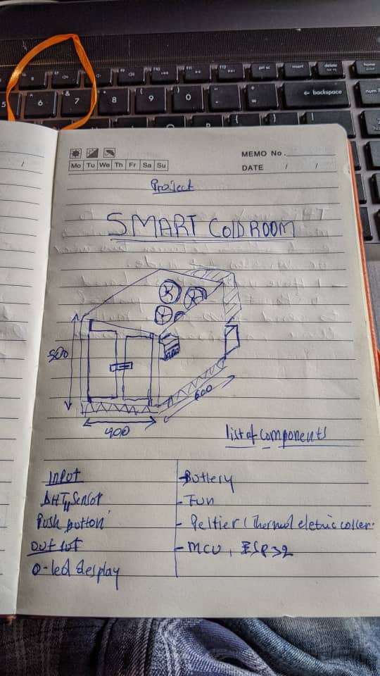

Project users
THE User of the project will be fermer and seller By preventing post-harvest losses in food systems, we can increase the availability of food worldwide without requiring additional resources or placing additional burden on the environment. Food losses happen at every stage of the supply chain, as commodities become damaged, spoiled or lost while harvested, handled, processed, stored and transported. To over come this we I decided to develop smart cold room
project development
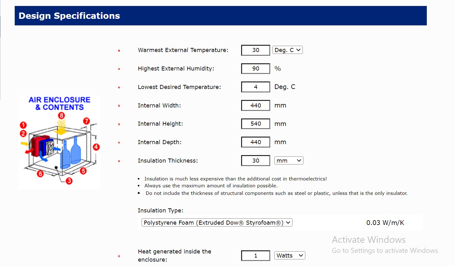
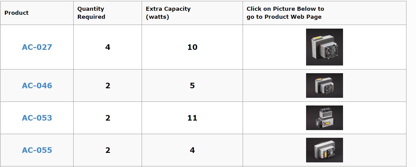
system sizing
- DESIGN
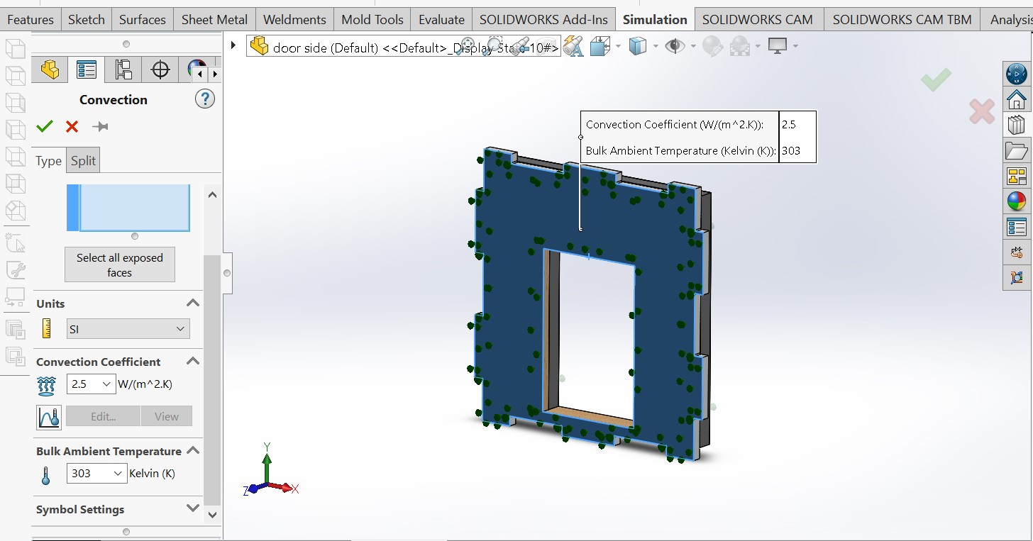
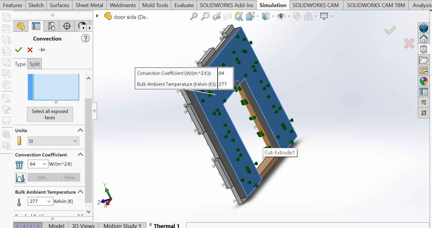
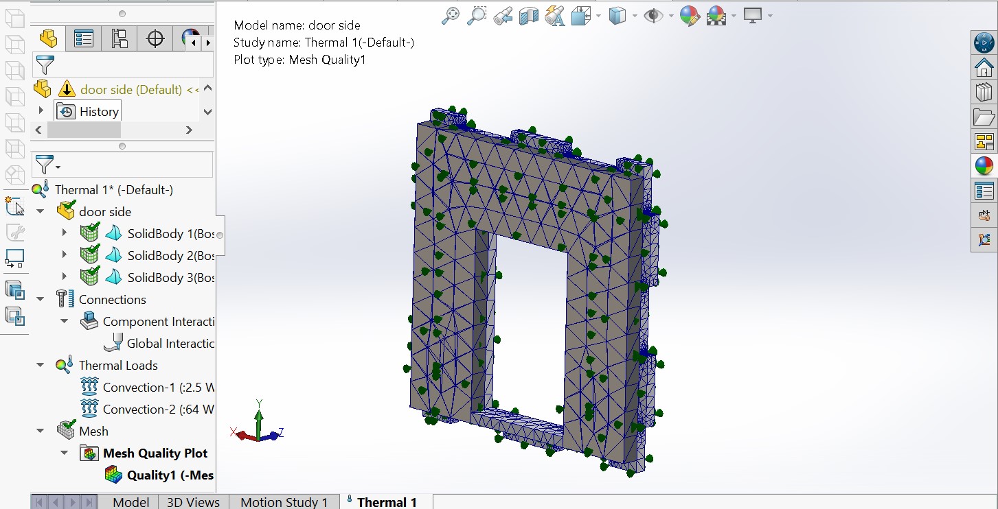
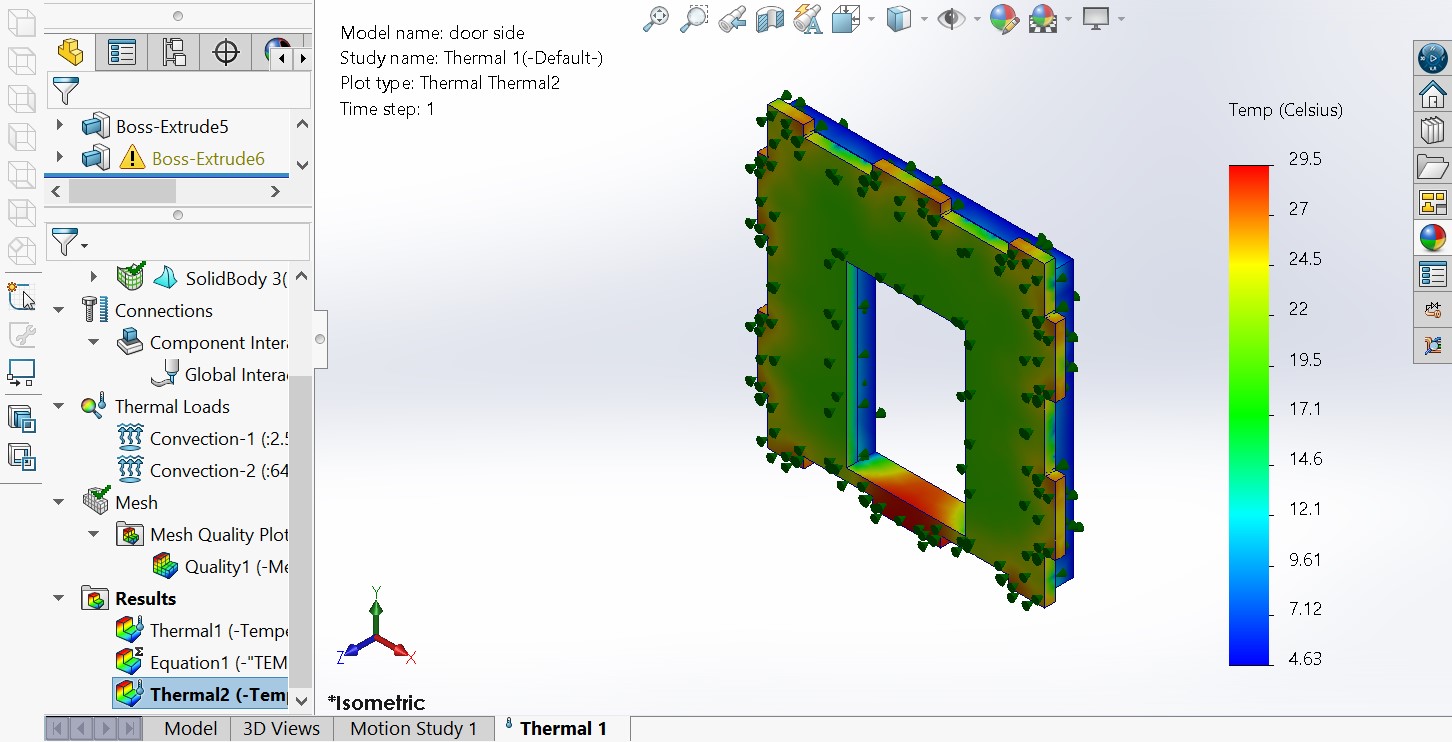
- THERMAL STUDY
- INTERFACE AND COMUNICTIION
- ASSEMBLY OF WHOLE PROJECT COMPONENTS
1.3D MODEL OF PROJECT
the design of my project is composed with two parts which is 3d design and eletronics even software design of interface
3D DESIGN OF MY PROJECT
I USED SOLIDWORKS SOFTWARE TO DESIGN WHOLES OF MY COLDROOM WITH ACTUAL DIMENSIONS , BELLOW A FLOW OF PROCESS OF DESIGNING JOURNEY IS ENDICATED
COLD ROOM HOUSING


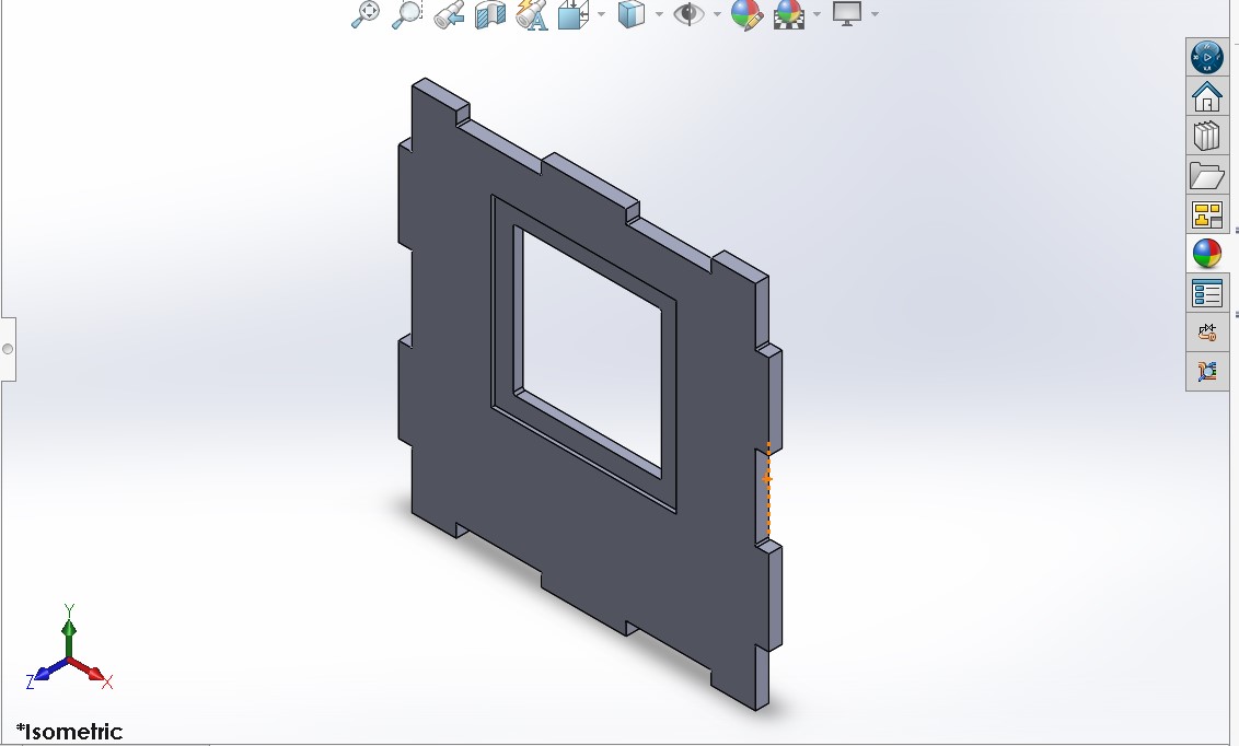
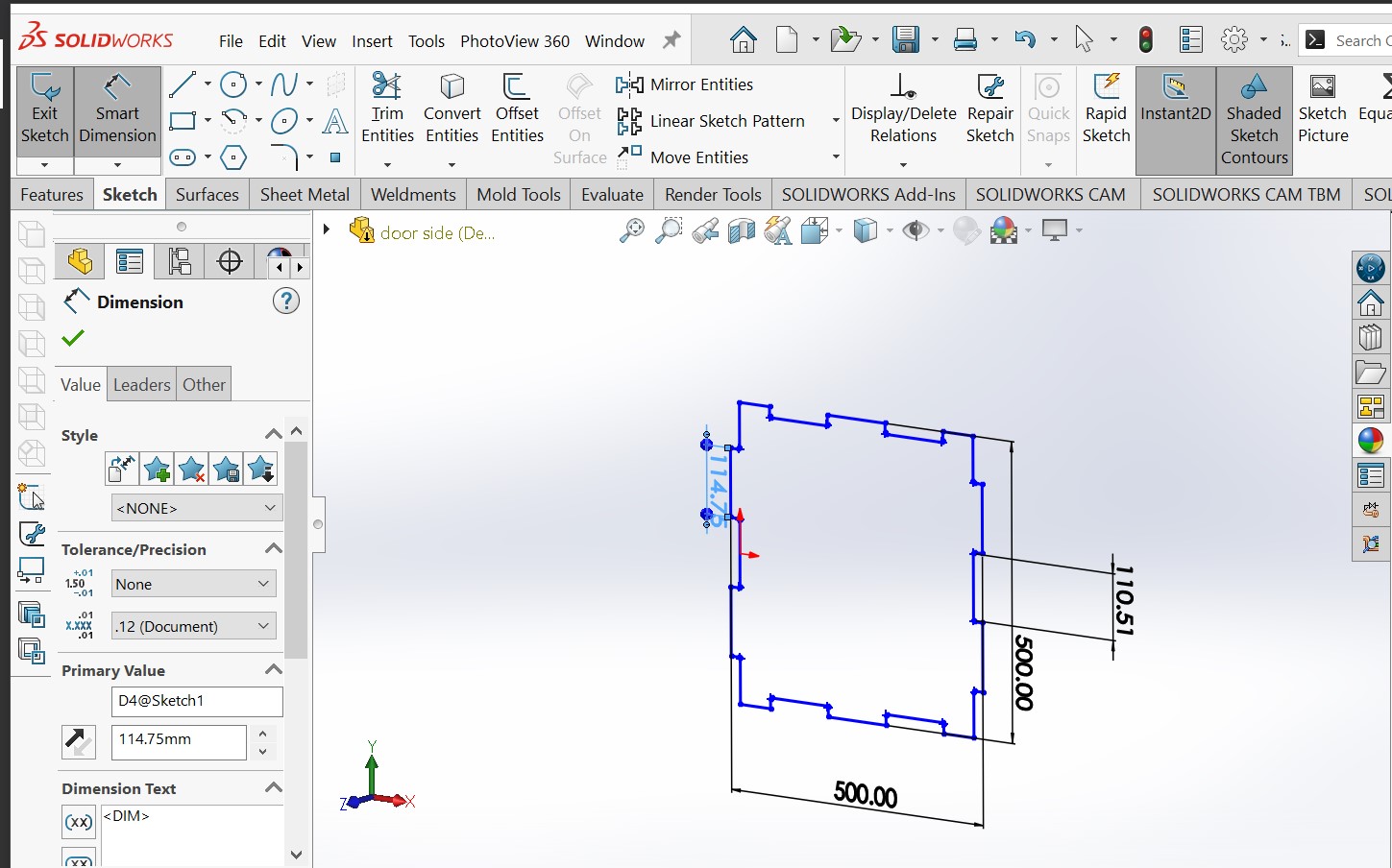
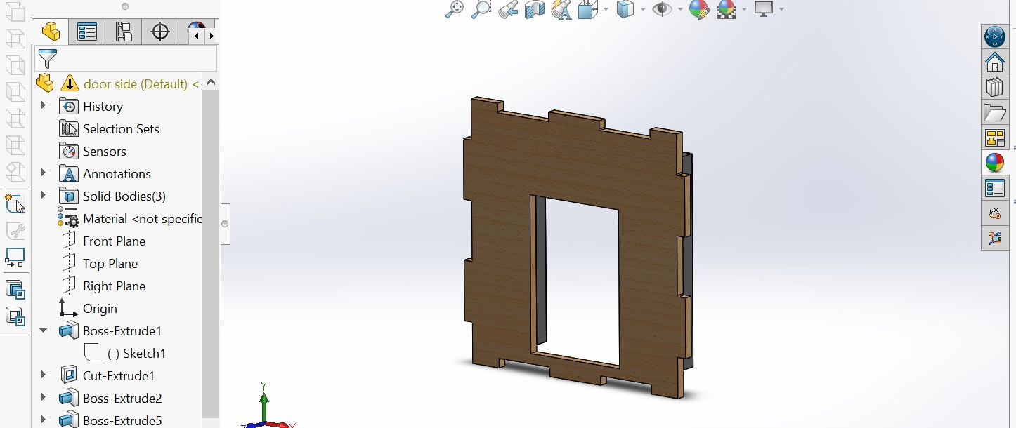
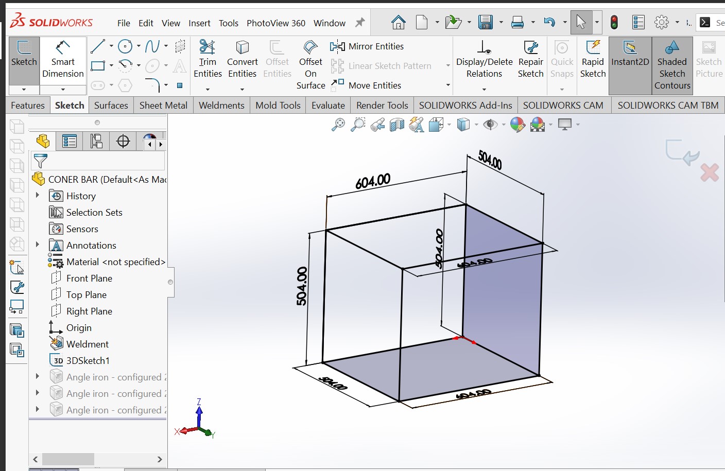
ALUMINIUM CONNER BAR FOR support
HERE i decide to use solidworks feature called weld mate in order to use standard size of coner bar wich is alll ready exist on the market
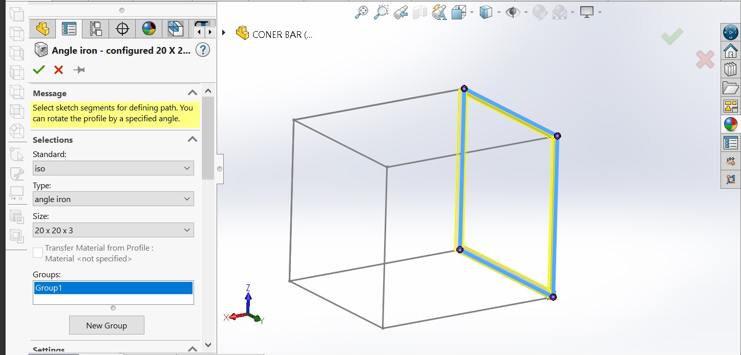
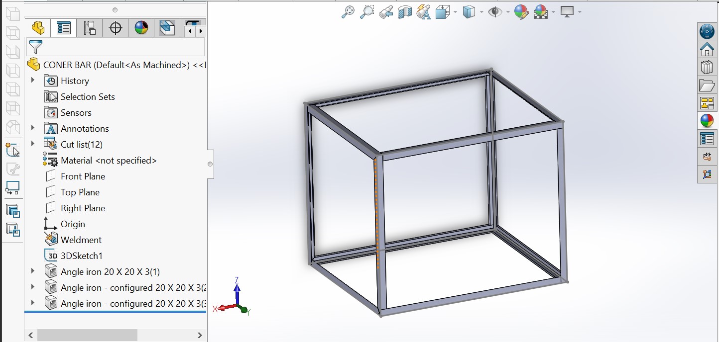
coolling unit cover
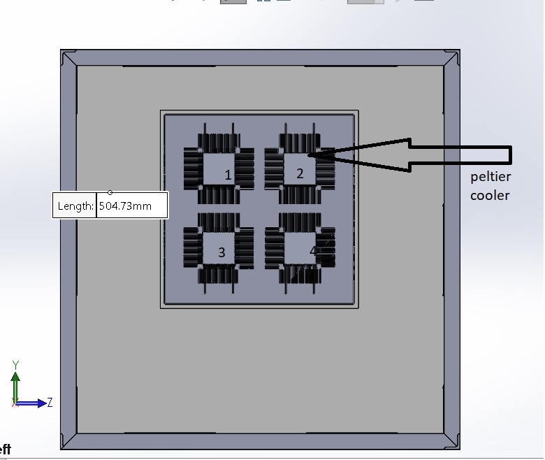
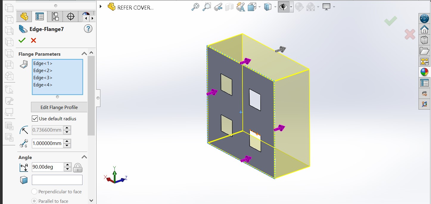
Interesting ,I used SOLIDWORKS SHEET METAL FOR DESING THE SHEET COVER WHICH WILL HOLDS FUNS AND PELTIA PLATE AND HEAT SINKS
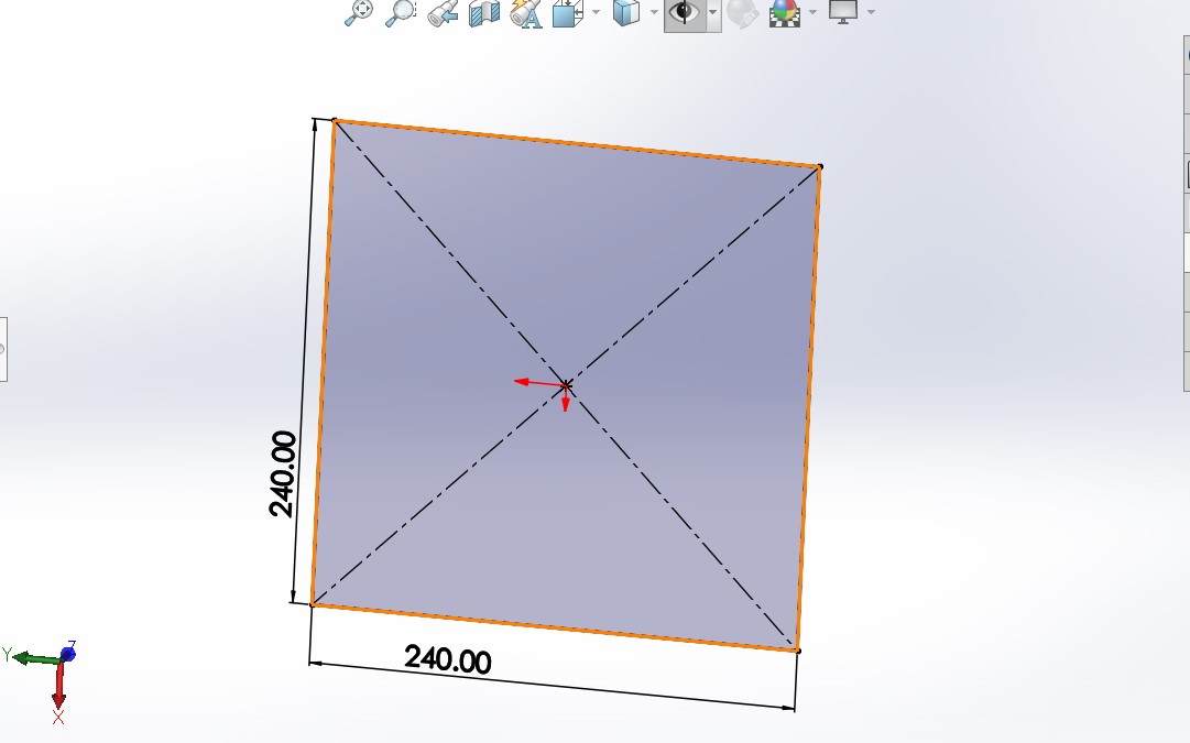
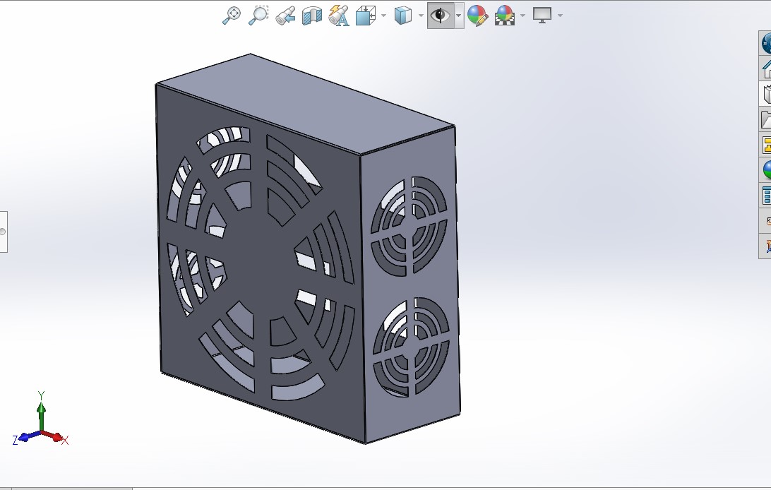
Heat sink
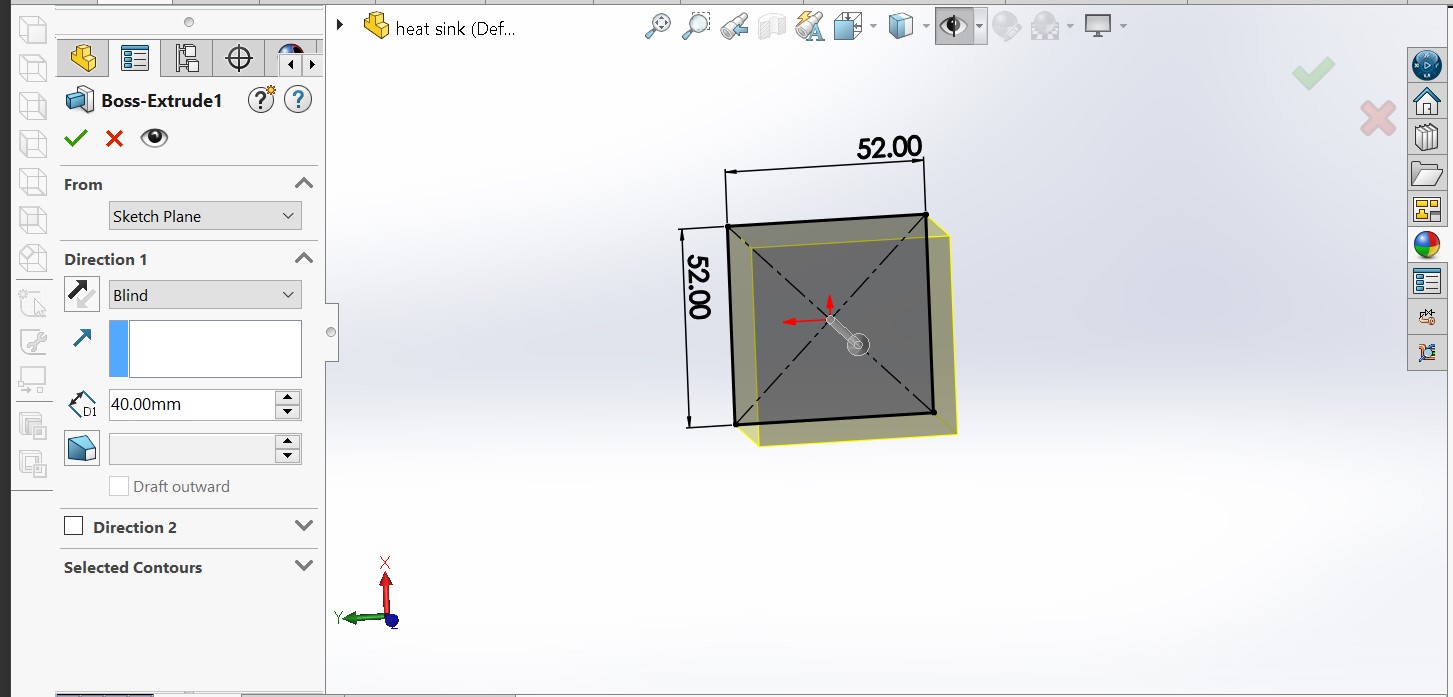
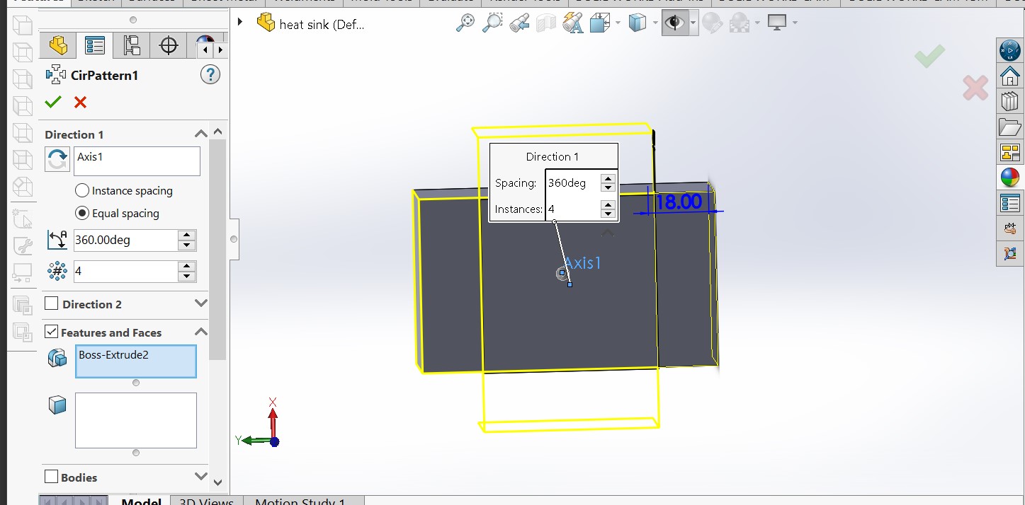
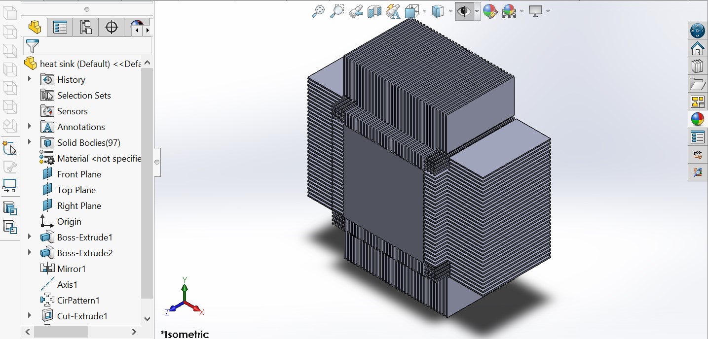
the model of heat sink is designed based on the raal product form second hand markets. I decided to to design heat sink to ensure the dimensions and disposition of heat sink to assembled with heat sinks in the cold rooom.
Full ASSEMBLY Project (3D FINAL MODEL)
I tried capture all view of the model in order to callify more detail
Manufacturing process of model of project
after design of full medel of the project export part by part as dxf for those which will be manufactured by substructive manufacturing process on CNC mchine. below there dxf file in vcarve pro software.


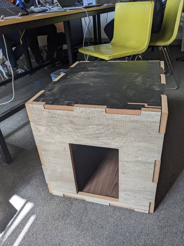
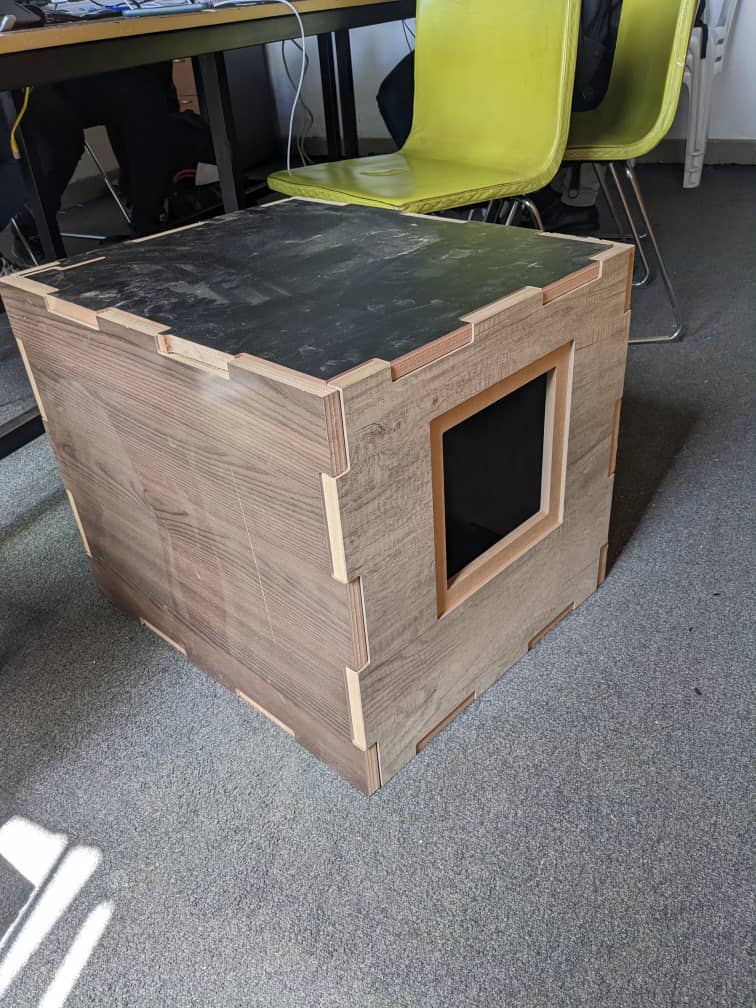
FINAL HOUSING MANUFACTED ON CNC OF COLDROOM
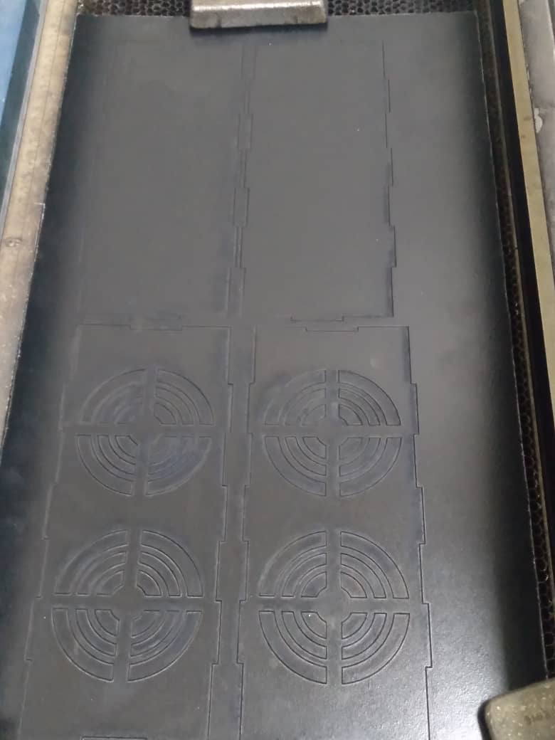
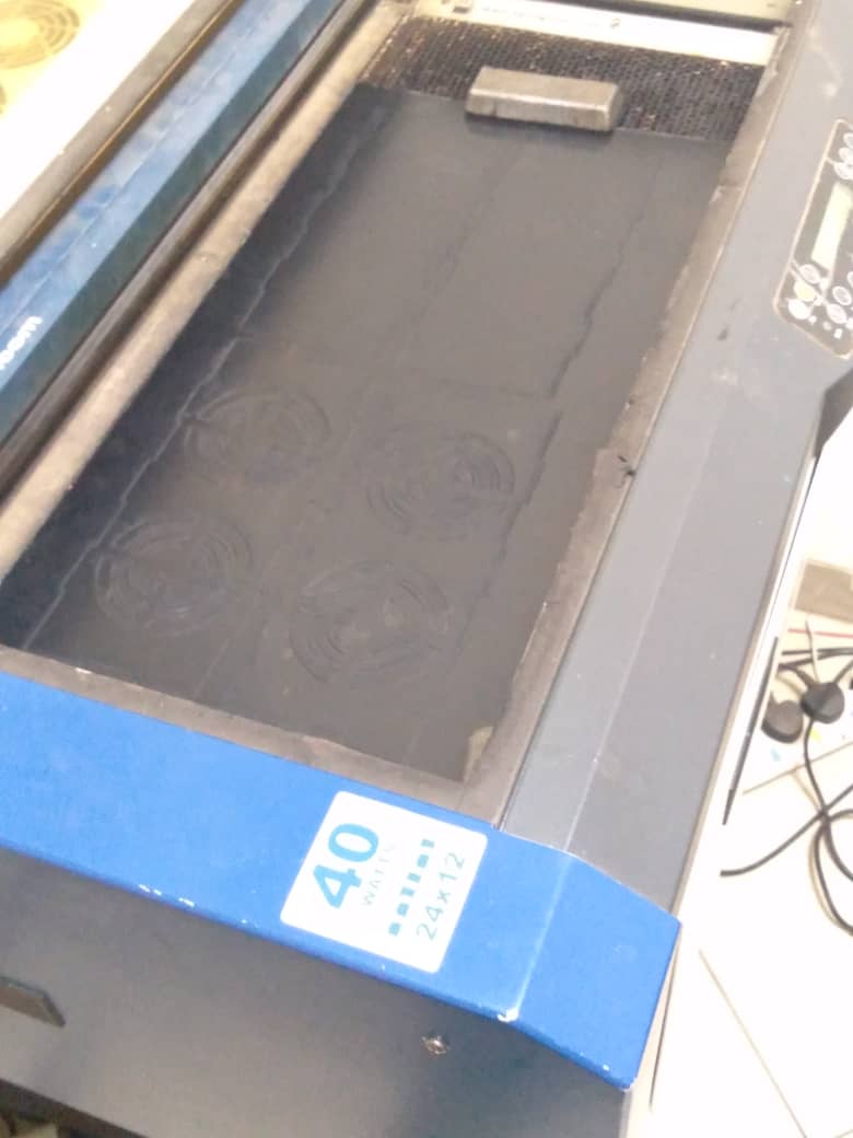
cooler manufacturing process on laser cuter.
laser cutter helps me in cutting small componets with high precision. bellow the attached photo shows dxf of cooller cover and its printing on laser cutter
.png)
.png)
