OUTPUT DEVICES
Assignment
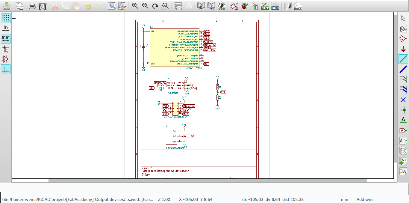
In this assignment we have to add an output device to a microcontroller board and program it to do something. For this work I worked with LCD display as an output device and I want to controll it. I designed a circuit to use in controlling the LCD display as shown in the image below.
Meaning of output device
An output device is a piece of hardware or peripheral that is used to display or present information generated by a computer or electronic device. It takes the processed data from the computer and presents it to the user in a human-readable format. The purpose of an output device is to provide visual, auditory, or tactile feedback to the user based on the input and processing performed by the computer.
Example of common output
1.LED (Light-Emitting Diode): LEDs are commonly used as output indicators. They can be programmed to turn on or off, or to display different colors, providing visual feedback.
2.LCD (Liquid Crystal Display): LCD screens can display text, numbers, and graphics. They are commonly used to provide visual information or user interfaces.
3.Buzzer or Speaker: These devices produce sound or tones based on signals from the microcontroller. They can be used for alarms, notifications, or generating audio feedback.
4.Motor: Motors can be controlled by the microcontroller to perform various actions, such as rotating, spinning, or moving objects. They are commonly used in robotics and automation projects.
5.Servo Motor: Servo motors are used for precise control of angular position. They can be used to control robot limbs, steering mechanisms, or any application that requires precise positioning.
6.Display Modules: These include modules like 7-segment displays, OLED displays, or alphanumeric displays. They can show numbers, letters, or characters, and are often used to present data or provide visual feedback.
7.Relay: A relay is an electromechanical switch that can be controlled by the microcontroller to control high-power devices or circuits. It allows the microcontroller to switch on/off external devices, such as lights, motors, or appliances.
8.DAC (Digital-to-Analog Converter): A DAC converts digital signals from the microcontroller into analog signals. It can be used to control analog devices or produce analog output, such as generating varying voltage levels for audio output.
Meaning of output device added to a microcontroller board
When an output device is added to a microcontroller board, it means that the microcontroller is connected to a hardware component that can receive signals from the microcontroller and produce a physical output based on those signals. In the context of microcontrollers, an output device can be any external component or peripheral that converts digital signals from the microcontroller into some form of tangible output. The microcontroller generates specific output signals based on its programming or input conditions, and these signals are used to control the behavior of the connected output device. For example, if an LED (Light-Emitting Diode) is connected to a microcontroller board as an output device, the microcontroller can send signals to the LED to turn it on or off, or even control its brightness or color. Similarly, a motor can be connected as an output device, and the microcontroller can send signals to control the motor's speed or direction. The addition of output devices to a microcontroller board expands its capabilities and allows it to interact with the physical world. It enables the microcontroller to control and manipulate external components, enabling applications such as robotics, home automation, sensor-based systems, and more.
Here are several common challenges or errors that occur in this week assignment.
1.Incorrect Wiring or Connections: One common mistake is to have incorrect wiring or connections between the microcontroller and the output device. This can result in the output device not receiving the correct signals or power, leading to unexpected behavior or no output at all.
2.Power Supply Issues: Insufficient or unstable power supply to the output device can cause problems. If the output device requires a higher voltage or current than the microcontroller can provide, an additional power source or appropriate power management circuitry may be necessary.
3.Incorrect Pin Configuration: Microcontrollers often have multiple pins or ports available for connecting external devices. Selecting the wrong pin or misconfiguring the microcontroller's pins can result in the output device not functioning as intended.
4.Programming Errors: Mistakes in the code or programming of the microcontroller can cause the output device to behave incorrectly or not respond at all. Errors such as incorrect syntax, improper timing, or logical errors in the program can lead to unexpected output or no output.
5.Compatibility Issues: Some output devices may require specific communication protocols, signal levels, or timing requirements. Failing to consider these compatibility factors when connecting and programming the device can result in errors or improper functioning.
6.Lack of Proper Initialization or Setup: Many output devices require specific initialization or setup routines to configure their operating parameters. Neglecting to properly initialize the device or not setting the required parameters can lead to unpredictable behavior or no output.
7.Insufficient Current or Drive Capability: Certain output devices, such as motors or high-power LEDs, may require a higher current or drive capability than what the microcontroller can provide directly. In such cases, additional components like transistors or motor drivers may be needed to properly interface the microcontroller with the output device.
Here are the trouble shooting i do on those errors occur in this assignement
1.Check Connections: Verify that all connections between the microcontroller and the output device are secure and correctly wired. Ensure that the necessary power, ground, and signal lines are properly connected.
2.Review Documentation: Refer to the datasheets, user manuals, or technical documentation for both the microcontroller and the output device. Pay attention to pin configurations, required voltage levels, communication protocols, and any specific initialization or setup instructions.
3.Test Power Supply: Check the power supply to the output device. Ensure that it is receiving the required voltage and current levels. Consider using a multimeter or voltage regulator to verify the power supply's stability.
4.Debugging Tools: Utilize debugging tools available for your microcontroller, such as a serial monitor or debugger. These tools can help monitor the behavior of the microcontroller and identify potential issues in the code or program flow.
5.Code Review: Review your code for any syntax errors, logical errors, or incorrect settings. Double-check variables, pin assignments, and timing requirements. Make sure you have properly initialized the output device and configured the microcontroller's peripherals or registers.
6.Simplify and Test: If you encounter difficulties, simplify your code or isolate specific functionalities. Test each component or feature individually to identify potential problem areas. Gradually add complexity while verifying functionality at each step.
7.Monitor and Debug Output: Use debug statements, print statements, or LEDs to monitor the behavior of your program and verify that it is reaching the desired points in the code. This can help identify where issues may be occurring.
8.Seek Community Support: If you're still encountering issues, seek assistance from online forums, community platforms, or microcontroller-specific communities. Describe your problem and share relevant code or hardware details. Others with similar experiences may offer insights or solutions.
9.Hardware Compatibility: Verify that the microcontroller and output device are compatible in terms of voltage levels, signal protocols, and communication interfaces. Ensure that the microcontroller has sufficient drive capability to handle the requirements of the output device.
10.Test with Known Working Examples: If possible, test the output device with known working examples or sample code provided by the manufacturer or the community. This can help determine if the issue lies with the hardware, connections, or programming.
Here is the process i used in this week assignment
Board design
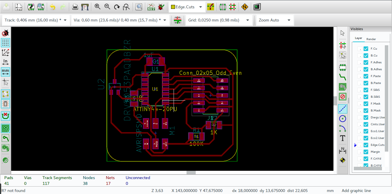
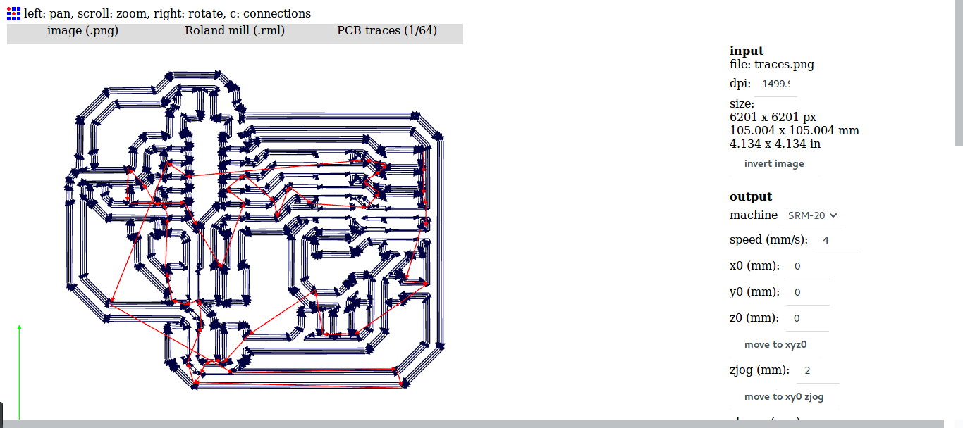
The next step is to trace the PCB for the cirtcuit as shown below
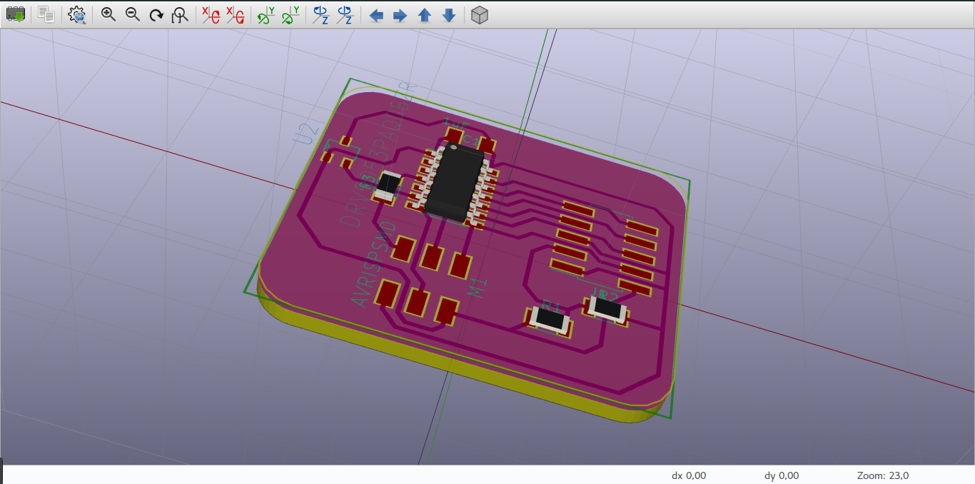
This image shows my circuit in 3d view
I moved on to create and edit RML file for the designed circuit.
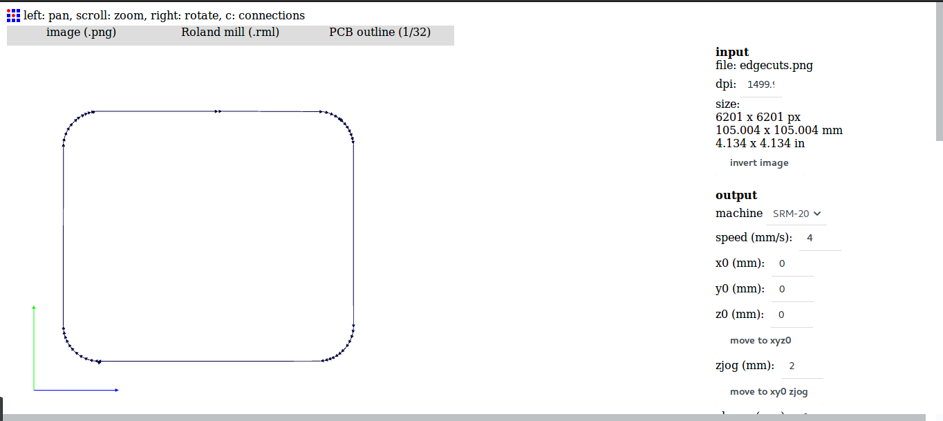
The next step was to do the outline cuts for the board.
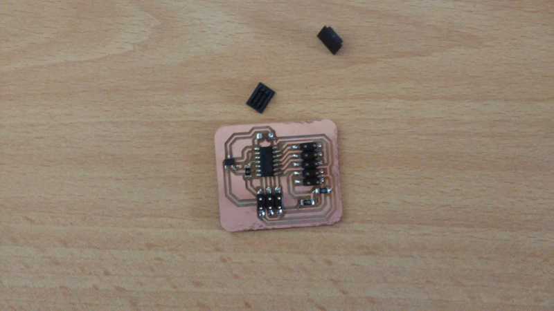
After milling the next step was to to do soldering the components on it
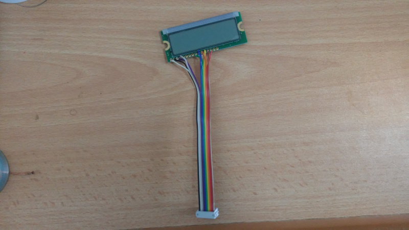
The image below shows the lcd to be used
Here is my video
Here is the orginal files