Electronic Production
Work to be done:
Group Assignment:
Here is the link to the groupe assignment
1.Characterize the design rules for your in-house PCB production process: document feeds, speeds, plunge rate, depth of cut (traces and outline) and tooling document your work (in a group or individually)
2.Test runout, alignment, fixturing, speeds, feeds, materials and toolpaths for your machine.
3.Document your work to the group work page and reflect on your individual page what you learned.
Individual Assignment
.Make and test the development board that you designed to interact and communicate with an embedded microcontroller
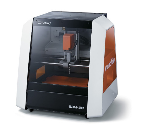
The machine to be used in my assignement is The Lab's PCB milling maching Roland MonoFab SRM-20
These are three main works to do:
1.Milling the PCB
2.Soldering components
3.Programming the board
The main objective of this assignment is to produce a FabISP board, which is an in-system programmer for AVR microcontrollers, designed for production within a FabLab. It allows you to program the microcontrollers on other boards you make
Group assignement
If you want to explore the group Assignment Click
PCB design rules refer to a set of guidelines and specifications that dictate how a printed circuit board (PCB) should be designed to ensure it functions properly and can be manufactured efficiently and cost-effectively.
Here is the link to the refference you can use it to find more about PCB design rules
Set-up Milling machine and Milling PCB
Set-up Milling machine
Here are the steps of setting up a milling machine
1.Safety first: Before starting any work, make sure you are wearing appropriate personal protective equipment (PPE) such as safety glasses, hearing protection, and a dust mask if needed. Ensure the machine is properly grounded and that the emergency stop button is easily accessible.
2.Position the machine: Place the milling machine on a solid and level surface, preferably bolted or clamped to prevent any movement during operation. Ensure there is enough space around the machine for easy access and movement of the workpiece.
3.Secure the workpiece: Use clamps, vises, or other appropriate workholding devices to secure the workpiece firmly to the milling machine table. Ensure that the workpiece is properly aligned and centered with the machine's spindle.
4.Install cutting tools: Select the appropriate cutting tool for the desired operation and mount it securely in the machine's spindle. Follow the manufacturer's instructions for tool installation and ensure that the tool is tightened properly using the necessary tools, such as a wrench or collet key.
5.Set spindle speed and feed rate: Refer to the machining specifications for the material being cut and select the appropriate spindle speed and feed rate. Adjust the machine's controls accordingly, using the speed and feed controls provided.
6.Set work coordinates: If your milling machine has a coordinate system, set the work coordinates based on the desired machining location. This can be done using the machine's digital readout (DRO) or by manually adjusting the table or workpiece position using the machine's handles.
7.Adjust machine settings: Set any additional machine settings required for the specific operation, such as depth of cut, cutting direction, or coolant flow. Refer to the machine's manual for guidance on adjusting these settings.
8.Test and verify: Before starting the actual milling operation, perform a test run with the machine's spindle turned off to check for any interference or misalignment issues. Make any necessary adjustments to ensure proper clearance and alignment.
9.Start milling operation: Once you have completed all the setup steps and verified everything is in order, you can start the milling operation. Gradually increase the spindle speed and engage the feed mechanism as required. Monitor the machining process closely and make any adjustments as needed.
10.Clean up and maintenance: After completing the milling operation, turn off the machine and clean up the work area. Remove any chips, debris, or coolant from the machine and surrounding area. Perform any necessary maintenance tasks, such as lubrication or tool inspection, as recommended by the machine's manufacturer.
Milling PCB
Here are steps to follow while milling PCB
1.Design your PCB: Use PCB design software to create the layout and circuitry of your PCB. Ensure that the design is optimized for milling, including appropriate trace widths and spacing, and pads for components.
2.Generate Gerber files: Export the Gerber files from your PCB design software. Gerber files contain the necessary information about the PCB layout, including the traces, pads, and drill holes.
3.Prepare the milling machine: Set up and prepare your milling machine following the general steps mentioned earlier in the setup process. Ensure the machine is properly leveled and calibrated.
4.Import Gerber files into milling software: Use a dedicated PCB milling software, such as FlatCAM or CopperCAM, to import the Gerber files. This software will convert the Gerber files into G-code instructions that the milling machine can understand.
5.Configure milling parameters: In the PCB milling software, configure the milling parameters according to your specific requirements. This includes specifying the tool size, cutting depth, speed, and feed rate. Consult the milling machine manufacturer's guidelines and the specifications of your PCB material for optimal settings.
6.Set the work origin: Establish the work origin point in the milling software, which will define the starting point for the milling process. Typically, this is done by aligning the origin point with a reference point on the PCB.
7.Load the PCB blank: Secure the PCB blank onto the milling machine's worktable using clamps or a vacuum fixture. Ensure it is properly aligned and firmly held in place to prevent movement during milling.
8.Run the milling program: Start the milling process by running the G-code program generated by the PCB milling software. The milling machine will follow the programmed instructions to mill the traces, pads, and drill holes on the PCB.
9.Monitor the milling process: Keep a close eye on the milling process to ensure it is proceeding as intended. Check for any issues such as tool breakage, excessive vibration, or incorrect cutting depth. Make any necessary adjustments or stop the process if a problem arises.
10.Inspect and clean the milled PCB: Once the milling is complete, carefully inspect the milled PCB for any errors, such as incomplete traces or broken connections. Clean the PCB to remove any debris or residue left from the milling process.
In this assignement i got refference my PCB design from the following
On the web i mentioned i found best and simple design for PCB
Here are the images of all steps i used in milling my PCB
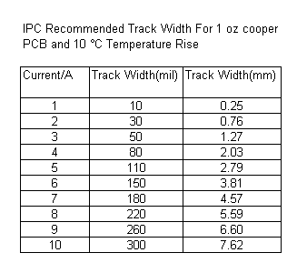
Here are the rules Tracing width and spacing:
These rules define the minimum width and spacing required for the traces on the PCB. The width of the traces determines their current carrying capacity, and the spacing helps prevent electrical interference and arcing between traces.
calculating width with calculator
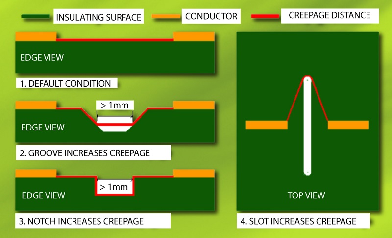
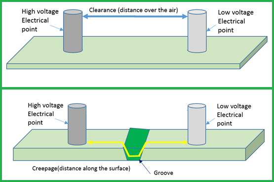
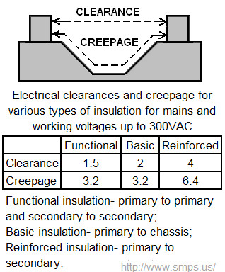
PCB Line Spacing for creepage and clearance as shown below
Machines to be used:
1.Milling CNC machine
2.Multimeter
3.Soldering Heat Gun
Materials to be used:
1.Tweezers
2.Solder Paste
3.1/32" DrillC
Here are the all process i used
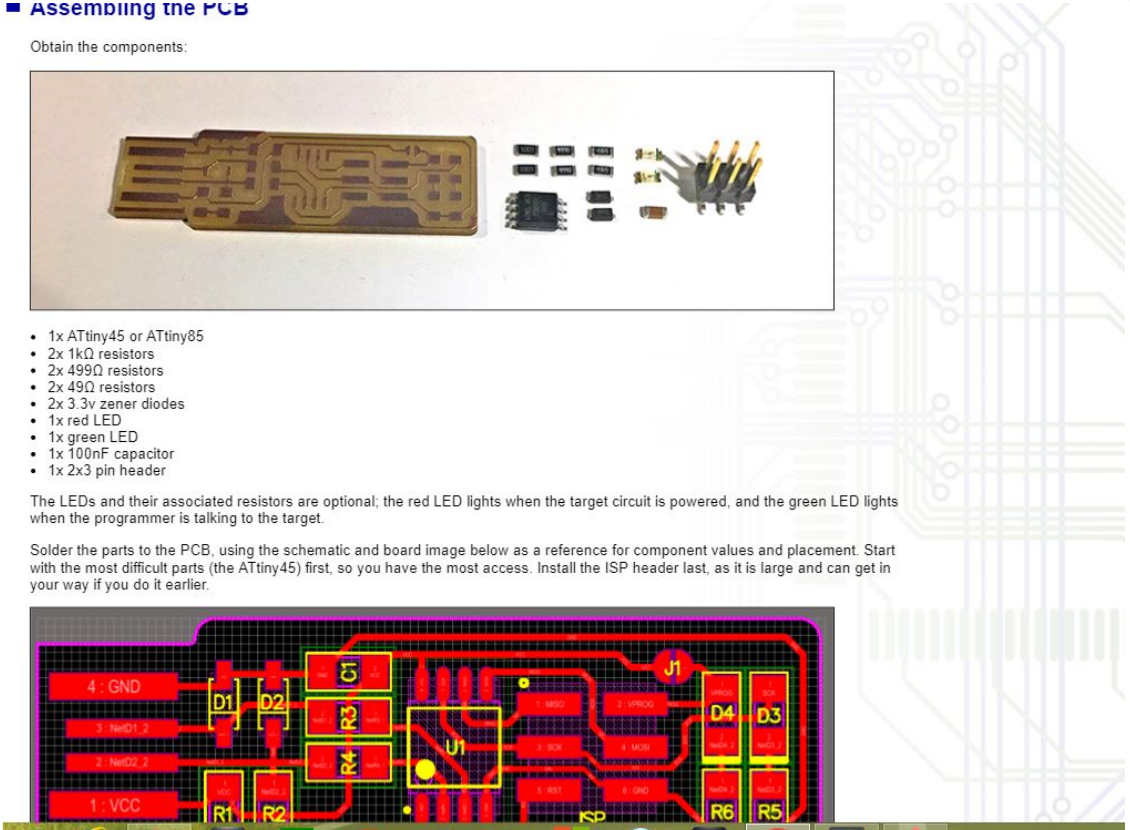
Here the first i do is to visit FabISP ATtiny45 web site to get the refference as shown in the image below
ASSEMBLING IMAGE HOW IT MUST BE
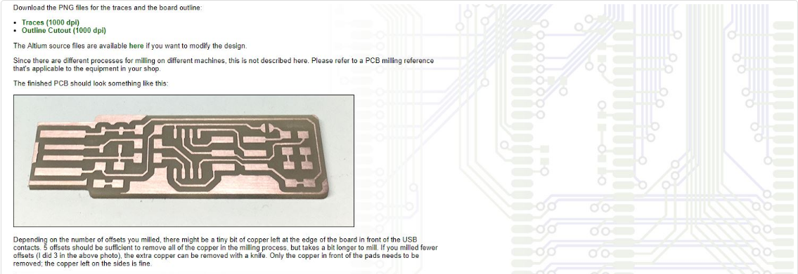
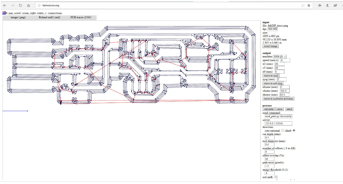
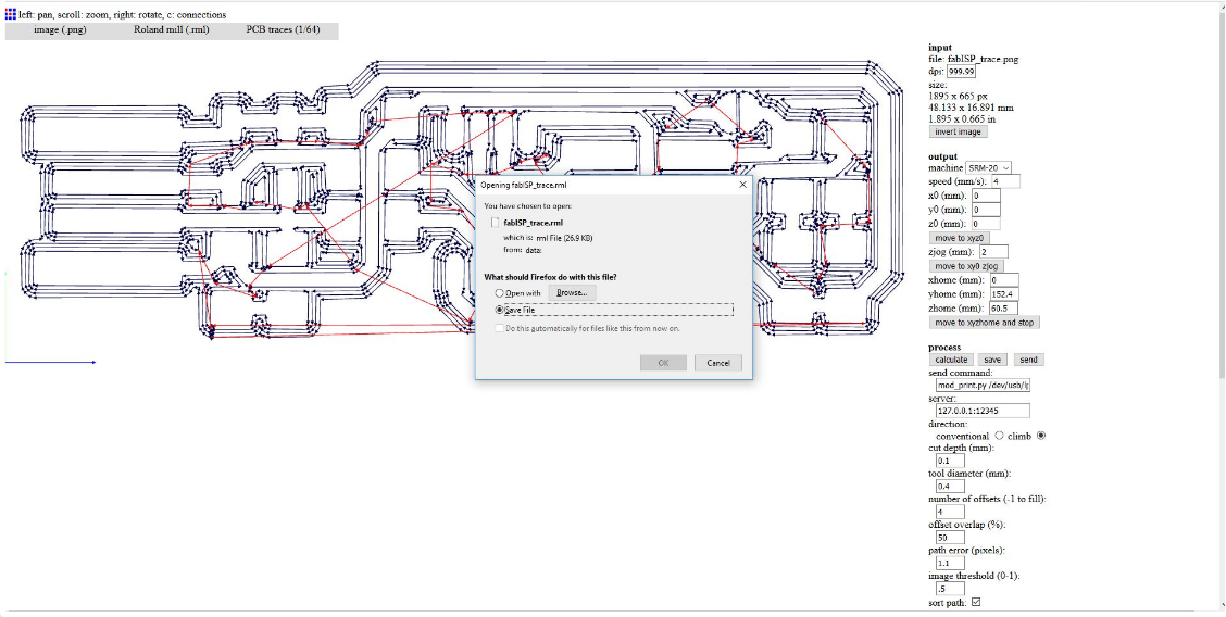
Here the next step was the prosess to make PCB traces
making PCB traces
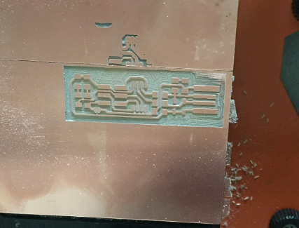
Milling process
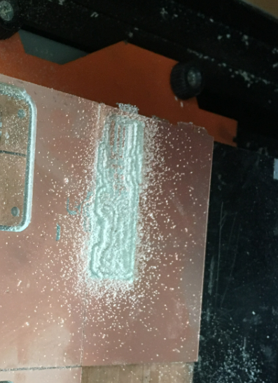
Problems in milling
Poor Surface Finish: If the milling cutter is not properly selected or is worn out, it can result in a poor surface finish on the machined part. Insufficient cutting fluid or improper cutting parameters can also contribute to a rough or inconsistent surface finish.
How i solved Poor Surface Finish
First i Check Tool Condition Ensure that the milling cutter is in good condition. A worn-out or damaged cutter can result in poor surface finish. Replace the cutter if necessary.
And then i Select the Right Cutter Choose an appropriate cutter for the specific milling operation and material being machined. Consider factors such as cutter geometry, number of flutes, and coating. Different cutters are designed for various applications and can significantly affect surface finish.
After that i Optimize Cutting Parameters Adjust the cutting parameters to achieve the desired surface finish. Parameters to consider include cutting speed (surface speed), feed rate, and depth of cut. Experiment with different combinations to find the optimal balance that produces a smoother surface finish and here the problem were solved.
How milling is done:
1.Setup: The milling process begins with setting up the milling machine. This includes securing the workpiece to the milling table or fixture and positioning it accurately for the desired machining operation. The milling machine may have different axes of movement, such as X, Y, and Z, which allow for precise positioning of the workpiece.
2.Tool Selection: Next, the appropriate milling cutter is selected based on the specific machining requirements. Milling cutters come in various types, such as end mills, face mills, ball nose cutters, and more, each designed for different cutting tasks. Factors considered when selecting a cutter include material to be machined, desired surface finish, cutting speed, and depth of cut.
3.Tool Setup: Once the cutter is selected, it is mounted onto the milling machine's spindle. The cutter may be secured using various methods, such as collets, end mill holders, or tool turrets, depending on the machine type.
4.Machining Operations: With the workpiece and tool set up, the milling operation can begin. The milling cutter rotates at high speed while the workpiece remains stationary or moves relative to the cutter. The movement of the cutter and the workpiece is controlled using the machine's axes. Facing: In facing operations, the milling cutter removes material from the face of the workpiece, creating a flat surface. Peripheral Milling: In peripheral milling, the cutter cuts along the periphery of the workpiece, removing material to achieve the desired shape or contour. This can include tasks such as profile milling, slotting, or contouring. Drilling: Milling machines can also perform drilling operations by using specialized drills or milling cutters designed for drilling holes. Cutting Parameters: The cutting parameters, such as cutting speed, feed rate, and depth of cut, are determined based on the material being machined, the cutter type, and the desired machining results. These parameters influence the cutting forces, tool life, and surface finish.
5.Finishing and Inspection: Once the milling operation is complete, the workpiece may undergo additional finishing operations, such as deburring or polishing, to achieve the desired surface quality. The finished component is then inspected to ensure it meets the required specifications and tolerances.
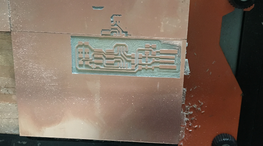
Here on this image you see the milling machine finish it's command
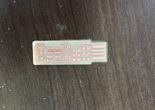
After cleaning my project
Here is my work after milling
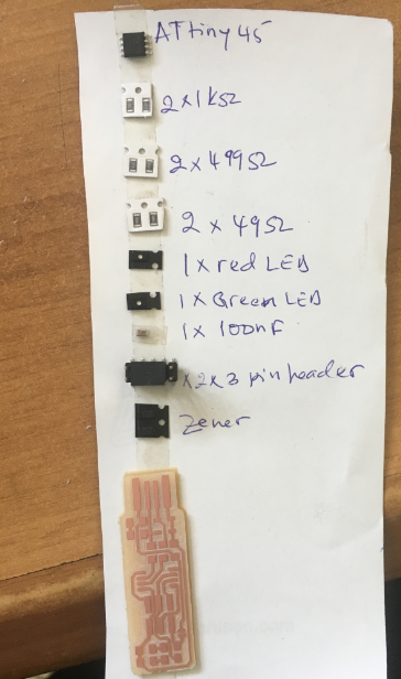
After milling process,I started soldering by selecting the needed components as shown below.
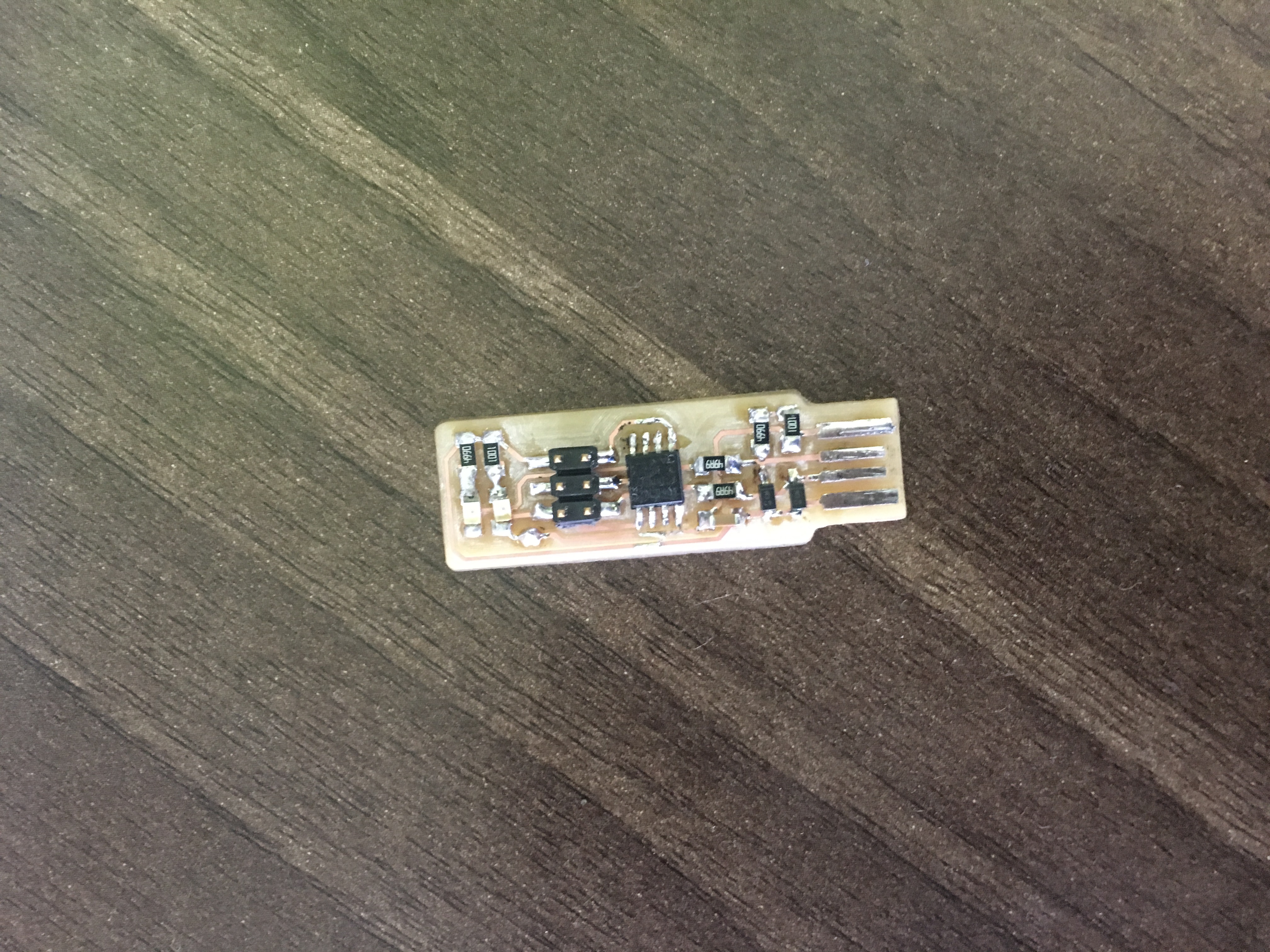
Final results
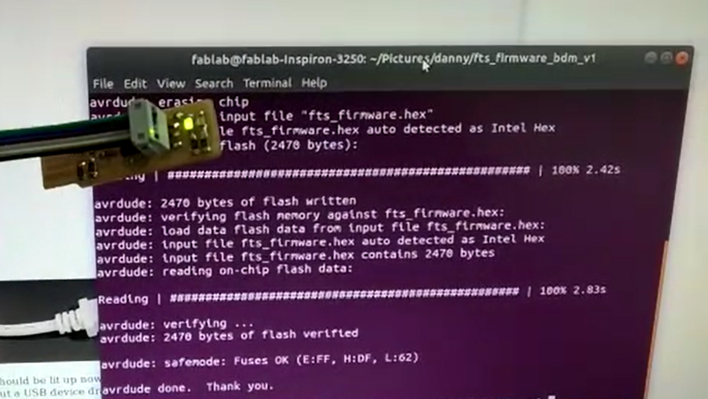
The last step was to program due to the type of my PC i used i used the following commands in terminal to configure my programmer.
.Runned nano Makefile to check which programme is selected and if the port is correctly selected.
.Runned make clean to remove any file that might have been created before.
.Runned make hex to create a hex file to uplaod in the programmer.
.Runned make fuse to setup fuses.
.Runned make program to upload the firmware in the programmer.
Here is my board working
Here is the video codes running