
WHY?
The project started as a question between me and my friend, "Can we further reduce the weight of CFRP manufacturing ." The question was asked because we liked fast cars. To make a car fast we can reduce the weight or increase horse power but increasing horse power increases weight so it has to be balanced and increasing the HP decreases fuel efficiency so it has to be balanced . In case of agility the car need to have less momentum in order to perform well in corners and well balanced weight distribution. by considering all these things we wanted to keep the weight to HP ratio bigger than 1. So in order to extract optimum performance out came to the conclusion of reducing the weight of the monocoque chassis . But nowadays with the introduction of CFRP the weight of the chassis are further reduced. Something that weighed over half a Ton is now less than 200 Kg now. What was once done with steel and aluminum has shifted to composite manufacturing. Even with all the composite manufacturing methods and CFRP patterns it can't still hold a candle against the Porche 917, which was introduced in the 1969 Le-Mans with a weight of of 45 Kg which used an aluminum magnesium alloy.
Braiding machine
Carbon Fiber Reinforced Polymer (CFRP) is a composite material used in a variety of applications for its high strength-to-weight ratio. One method of manufacturing CFRP is using braided tubes. The braided tubes are made by weaving carbon fibers together into a hollow tube shape. The tube is then cured in a high-pressure autoclave to harden the resin and create a strong bond between the fibers. Once cured, the tube can be cut to size and used in various applications, such as in the aerospace industry for lightweight structural components.

Currently, there are CFRP manufacturing processes that use braided tubes in sports and cycling industries. These processes use a wax core to create the base model, and braided tubular CFRP is layered all over them. However, this was not satisfactory for us because the individual tubes do not have any connection between them. To join them, additional CFRP is required as joints, which would break the link between individual fibers. We wanted something more than that. Considering the manufacturing process, we actually wanted to define every fiber within the skeleton. To this day, I see this as a dream. But considering practicality, we decided to create a braiding machine that can continuously braid an interlinking skeletal structure.
The Machine
My one of the reasons for choosing Fab Academy was for perfecting this design. This was something I had in my mind for a few months. As stated above, I wanted to perfect composite manufacturing. For that, I needed to define every fiber in that structure for better force distribution. However, the machine I proposed is not capable of that feat. The idea is to make skeletal structures from composite manufacturing, which can interlink at the joints. So, for that purpose, I designed that machine.
The machine consists of a normal braiding machine with a little modification. To do that, I referred to some designs from the internet and got a basic understanding of the braiding machine.
The mechanism of the machine has three parts that are in contact with each other but not connected. The connected mechanism for a braiding machine is less, so fewer joints need to be considered. However, the mechanisms need to be designed so that the gears, guides, and pathways are correctly designed. Interestingly, I can see the mechanisms clearly and I am confident that I can make it work. The pathways were designed such that the guides from the opposite pathways should not merge. Also, the pathway needs to be continuous throughout the design, without hindering the movement of another guide and should be easy to move.
The guide should be designed so that it can move along the paths without any hindrance, meaning it needs to have a minimum thickness. Additionally, the guide should not create any disturbance due to radius change of the pathways. Because the pathways are semicircles with different radii, the guide should be able to incorporate both of them. Lastly, the guide should not go into another path. If it does, it will cause major machine problems. So, I need to design it in a way that it will not go back into other paths. With that in mind, the design of the mechanisms of braiding was completed.

Then came the modification of the project. I needed to modify the project so that it serves my purpose as a machine which can braid skeletal structures. The method I chose was fairly simple. In braiding, there is a process called core braiding, where the material is braided over a core of other material. In theory, I can braid in the shape of the core supplied, but the downside is that I cannot braid if there are more than 2 links in a joint. So, the idea I proposed was to take the core outside the braiding machine, which is usually situated at the center, and braid over it. In theory, it is possible, but in practice, it has major downsides due to the fact that it may disrupt the pattern of the design. To overcome that, I decided to design a guide as a backup plan so that I will have a uniform pattern without compromising structural stability.
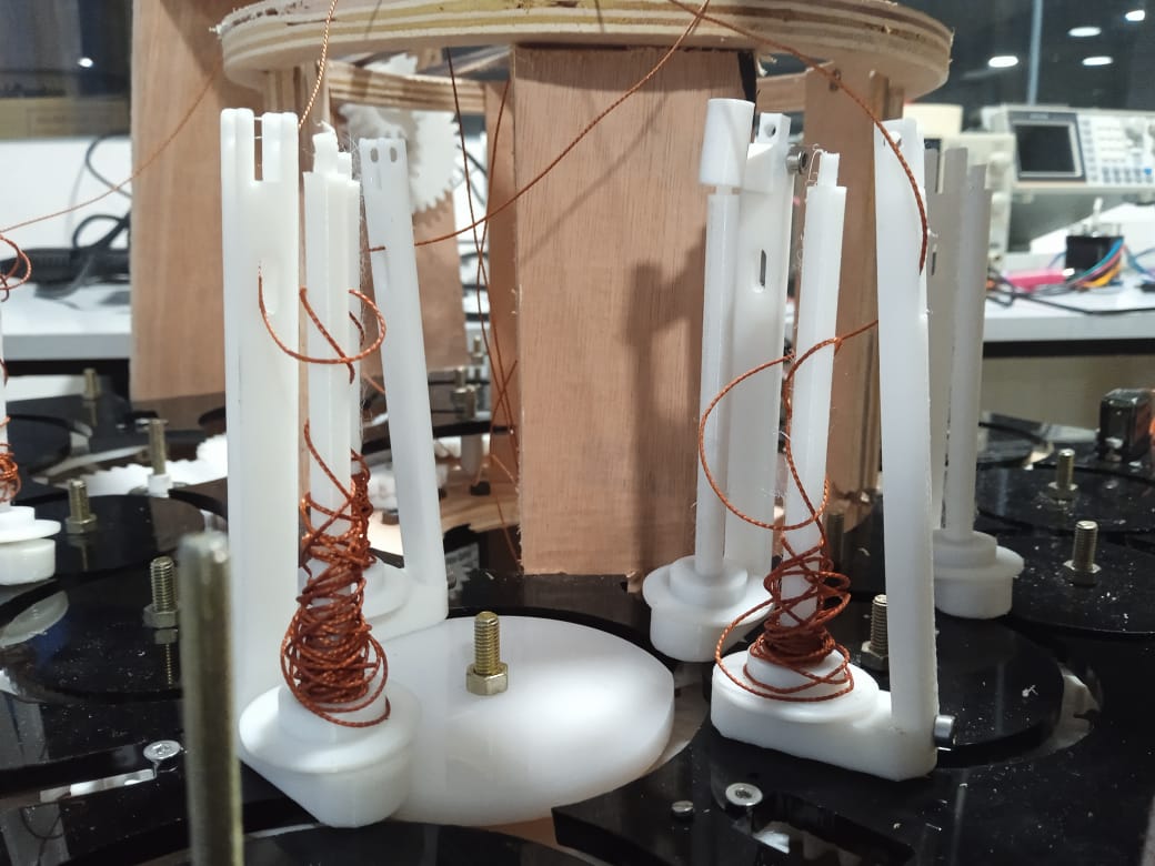
The other problem that arose due to displacing the core to the side was that the length of the thread varied when it moved away from the displaced core. It was not much, but the differences in length caused imperfections in the braiding machine. So, in order to reduce the length, the system required a length corrector to adjust its length. Basically, the bobbin is a rotating cylinder, so adding rotational effect was the only possible outcome. I initially thought about adding motors with a slip ratchet mechanism so that the motors would be constantly rotating. Another option was to add current sensing to motors so that if the tension gets higher, it will turn off the motor. However, it wasn't a viable option because the motors' wires would get tangled up. So, it was not an option at all. Thus, I decided to add mechanical constraints to the machine. I created a fixture-based assembly with gears and a curved rail to rotate the bobbin, and the flexures would bend according to the tension in the machine. I had tested the mechanism in 3D printing week and was confident that it would work.

To complete the braiding process, the bobbin needs to make a full rotation around the core. So, a rail is in order. The idea was that the servo gripper on the rail would pick up the part of the bobbin, come around the core, and go through a two-step bobbin winding process to complete the circle. If we need to properly do it, we can use robotic arms to make the process work, but I am not there yet.
After a while, I calculated the components required for the machine to work in bare minimum. It required at least 6 stepper motors and 1 servo motor. The mechanisms were too complex, consisting of many parts. I have been 3D printing them, but I am nowhere near perfection. That's when the second design came into play. Jogin proposed an idea of a braiding machine to me that can also function as a normal braiding machine. The machine I proposed was function-specific; it can only work for my intended purpose, not any other braiding operation.
The Other Machine
The idea was to create a machine that works as a braiding machine and also as a skeletal braiding machine. Jogin came up with the idea to create a braiding machine that makes both work possible. The idea was to create a braiding machine with a reservoir to store the bobbins. In theory, it can create skeletal structures by changing the braid into the reservoir of the machine. So, when it comes to joints, the machine will distinguish the different links and create branches by using the braids in the reservoir.
So, with that in mind, I started my design. I have already completed designing the guides, paths, and bobbins of the braiding machine for the previous machine. Now, I need to make it fully into a braiding machine. To do that, I need to make the necessary requirements for the braiding machine, including a top part to pull the thread (the top thread pulling part assembly) and also my experiment, the reservoir.

The funny thing is that the reservoir always works in pairs in order to accommodate the opposing threads. The said design is important. If there is only one reservoir, only threads going in one direction can be collected. Well, it is not functional and not good, but for the experiment of that reservoir, it is necessary. The design is such that it will do the normal braiding process and it will also be in my experiment.
I worked based on my previous design and modified them a little bit. The things I added were a reservoir, which can hold the bobbins and can rotate using a separate stepper motor. While designing the reservoir, one thing I wanted to look into was the size of the reservoir diameter. The diameter of the reservoir should be larger than the diameter of the paths, and also the diameter of the reservoir should not be larger because it will consume more of the path. So, it was carefully calculated to find the sweet spot.

Because of the introduction of the reservoir, there is a break in the flow of guides. Naturally, the bobbins have a tendency to go in and not go into the reservoir. Even if we rotate the reservoir, the tendency still remains. So, in order to have better control of the mechanism, a servo-actuated guiding system is introduced. In the normal position, the guides will not permit the bobbins into the reservoir, and in the actuated condition, the servo will open a path to the reservoir and guide the bobbin into the reservoir, and vice versa.

The other thing in the design was the top part. The top part is supposed to have a pulling mechanism to pull the threads out of the design. I designed it with silicone in mind to make a casted piece out of it so that I can cast the flexible gears. The reason for choosing flexible gears was because the thread should be pulled and it should not clog in the gears. In the case of a sturdy object, it should not break. I used a linear rod and a stepper motor in that part of the design because I wanted to have better control over the speed ratios of the main motor and the pulling motor.
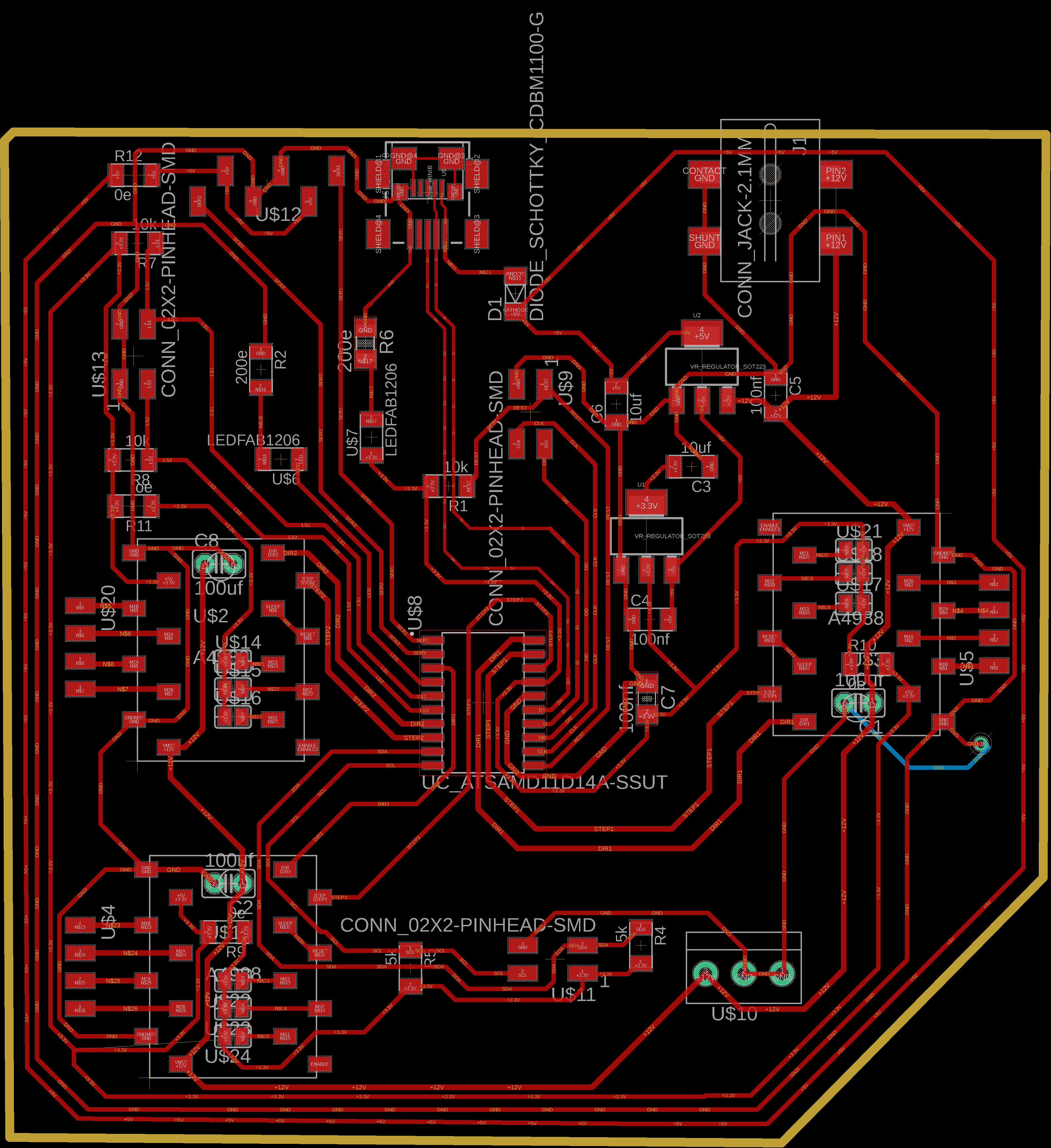
Electronics
The electronics consist of 3 stepper motors, 2 servo motors, a limit switch, and I wanted to connect a serial monitor to the computer because I had no purpose in having WiFi connectivity. Also, it had 2 limit switches, and it does not require any interrupt pins. With that in mind, I chose the SAMD11D microchip, which was ideal for my use.
The reason for choosing the chip was because of my familiarity with it, and it had an adequate number of pins for my use. With that in mind, I began designing in Fusion 360. Since I had 3 stepper motors, it was sufficient to have a 12V supply to the machine. I added a 12V input pin and SMD-type 12V connectors. For reverse current protection, I added it to the micro USB pin. After completing all of that, I showed it to my instructors and was ready to mill.
The design and milling process were fairly easy and went on without any issues. I tested all the programs and circuits for my board, and everything was working fine. I completed the circuit and was ready to program the board.
Manufacturing
Process I used for this project are:
- Wood CNC milling
- 3D printing
- Laser cutting
- Circuit Designing
- PCB Milling
- Soldering & Assembling
- Embedded Programming
Prior to manufacturing, what I did was create a small replica and tested the mechanisms of the braiding machine. By testing the mechanism, I was able to understand and fix any issues and preliminary errors. The mechanisms were working fine without any issues, which gave me some confidence in large-scale manufacturing.
3D Printing
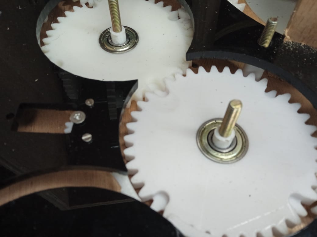
My design consisted of laser cutting wood, milling, 3D printing, small casting, and a small metal milling. Most of the mechanical parts were 3D printed. However, the 3D printed gears had some clearance issues, so I added a 0.2 mm clearance for a loose fit of the gears. The bobbin parts were also 3D printed, but they had too much play and were easy to pop out if a pulling force was applied. To address this, I added a notch at the bottom of the design to provide a better fit.

3D printing is the easiest and simplest process, which is why it was highly favored in the fab lab. It is also a preferred method in my project, as most of the mechanisms for the braiding machine were manufactured using this process. The gears of the mechanism had a notch on top, which is difficult to mill in metal. However, due to the accessibility of the 3D printer, I was able to manufacture it with ease. There were two types of gears that were formed by meshing them and creating a notch for the guides.
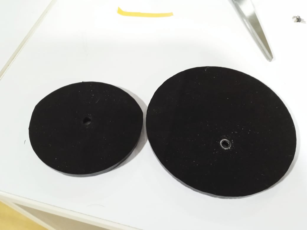
Most of the bobbin and its parts were 3D printed. The bobbins were 3D printed and assembled together to make the machine. Initially, the bobbin had some issues with its meshing and rotational clearance, but I was able to fix it by the end of the project. The 3D printed bobbin had a bearing at the center to facilitate its rotation with ease.
Another thing I did was 3D printing flexible gears using TPU. Initially, I was focused on molding them, but I changed my approach due to the complexity of the design and time management. 3D printing with TPU was the most viable option, so I went with that.
CNC Milling
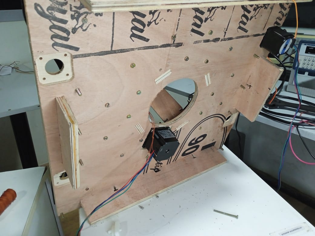
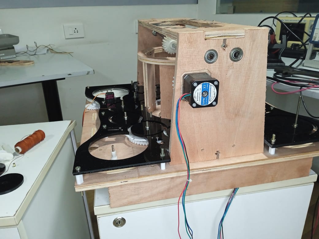
The base and structural parts of the machine were made of wood. I used the Zund universal cutter in the lab because of its speed and automatic tool changer (ATC) feature. The ATC made it easy to change tools, and the machine provided a better finish compared to the shopbot. So, I used the Zund to mill the wood, and it was a fairly easy process.
The base consisted of various designs, including normal routing, pocketing, and other machine operations. It had 2 stepper motors mounted at the base, and its purpose was to support all the gears and mechanisms of the machine. Since I was working with plywood, any errors in the machining process would greatly affect the machine's performance. Fortunately, the machining was carried out without any issues, and the pocket clearing process worked well. Once all that was finished, I proceeded to assemble the base, and the assembly went smoothly. The base functioned perfectly fine.
The next step involved machining the top part of the machine, which was relatively easy. Similar to the base, I didn't add any clearance because the base required a tight fit. Despite having screws to tighten the parts, I didn't need to use them because the components fit together perfectly and looked fine.
Laser Cutting
The pathway for the guides was manufactured using a laser cutting machine. Laser cutting made the job easy and provided good results. I was able to cut the acrylic for the desired pattern within an hour, and after that, I was ready to assemble the machine.

The laser cutting machine I used for my project proved to be highly efficient and provided me with excellent clearance. The kerf, or the width of the cut made by the laser, was extremely precise, measuring close to one point. This was a crucial factor in my decision to opt for the laser cutting machine, as it offered me sufficient clearance for my requirements.
One of the significant advantages of the laser cutting machine was its superior finishing quality compared to a milling machine. While milling machines often produce rough finishes on the cut surfaces, the laser cutting machine delivered a much smoother and refined finish. Despite the presence of an angled light in the laser cutting process, which could potentially introduce slight angular variations, it never posed any significant issues in my project.
Assembly
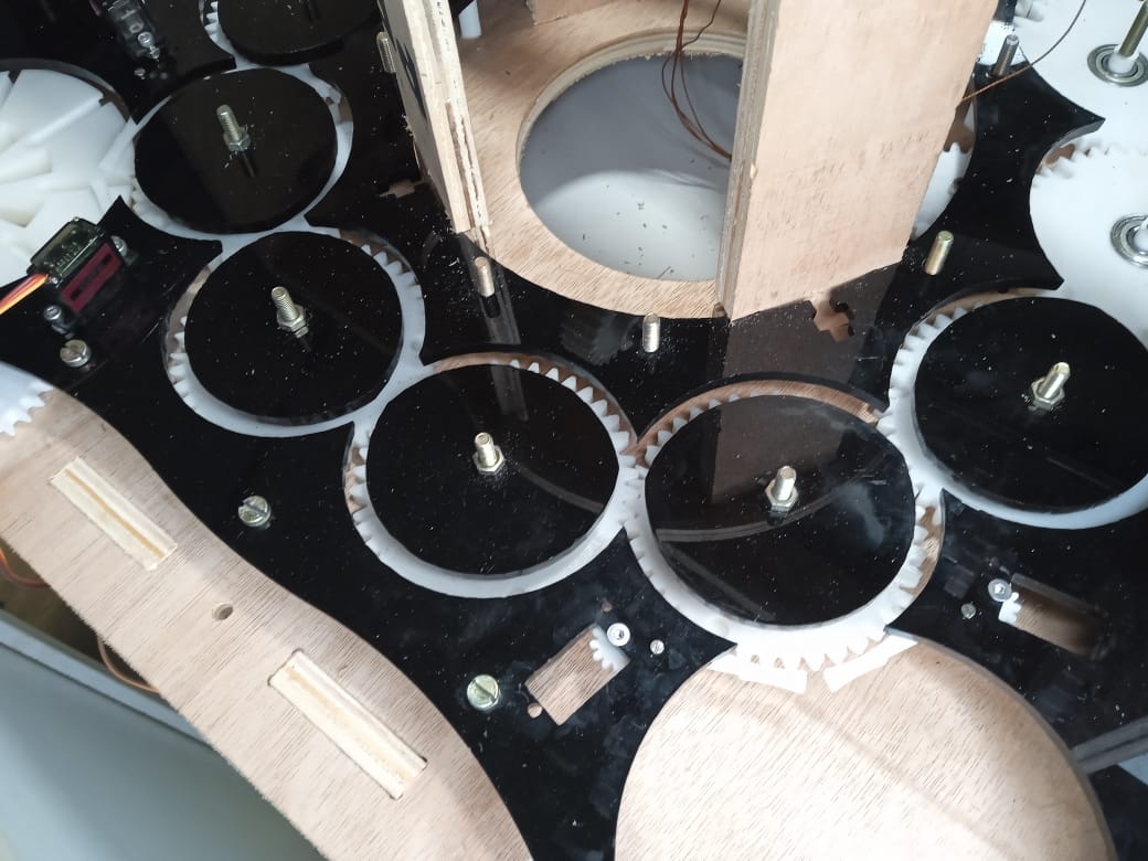
First, I assembled the gear supports, which were 3D printed, onto the base. Then, I fixed the bearings in the gears and secured all 12 gears to the base. After that, I ran the program for the stepper motor on the board, and it was working in harmony with the gears. Next, I assembled the top guide and screwed the individual parts. Once the parts were fixed, I installed the reservoir and the supporting gears.
After installing all the parts, I needed to add the servo actuators. Initially, I intended to use metal, but the 3D print gave me enough strength, so I decided to use it for the final project for the time being.
Finally, after assembling the TPU gears, I was able to complete my design, and I was ready to run my machine completely.
Bill Of Materials
Programming
The programming of the board was done using the Arduino IDE. I chose to use it because I have been using it since the beginning of the academy and was familiar with the code and programs.

The programming was done before, and I needed to have debugging in the case of servo motors because the Fab Sam core was not supporting the servo motor. So, I needed some more time to actuate the servo and the reservoir.
Final Presentation
During the presentation, the guides were experiencing some wobbling, but other than that, the braiding machine was working fine. It was a good learning experience for me, and I realized that I need to do a better job at programming and actuating the reservoir.