
9.OUTPUT DEVICES
Group Assignment
For this week, I am considering creating a board that can control two stepper motors simultaneously and potentially connect to an LED display to showcase its outputs. Admittedly, my experience with stepper motors and project-specific boards is limited. Therefore, I have referred to various websites and consulted with my batchmates, especially Sibin and Shaheen, for their expertise on these matters. I am also interested in implementing current limitation to turn off the stepper motors. Let's see how well I can execute this project.
Design

For this week, I have decided to focus on controlling two stepper motors in unison using the SAM D21E Microprocessor and an A4988 motor driver. To design my project, I have opted to use Fusion 360 as my primary design platform, as opposed to my previous use of KiCad during the past week. I find Fusion 360 to be an excellent designing software.
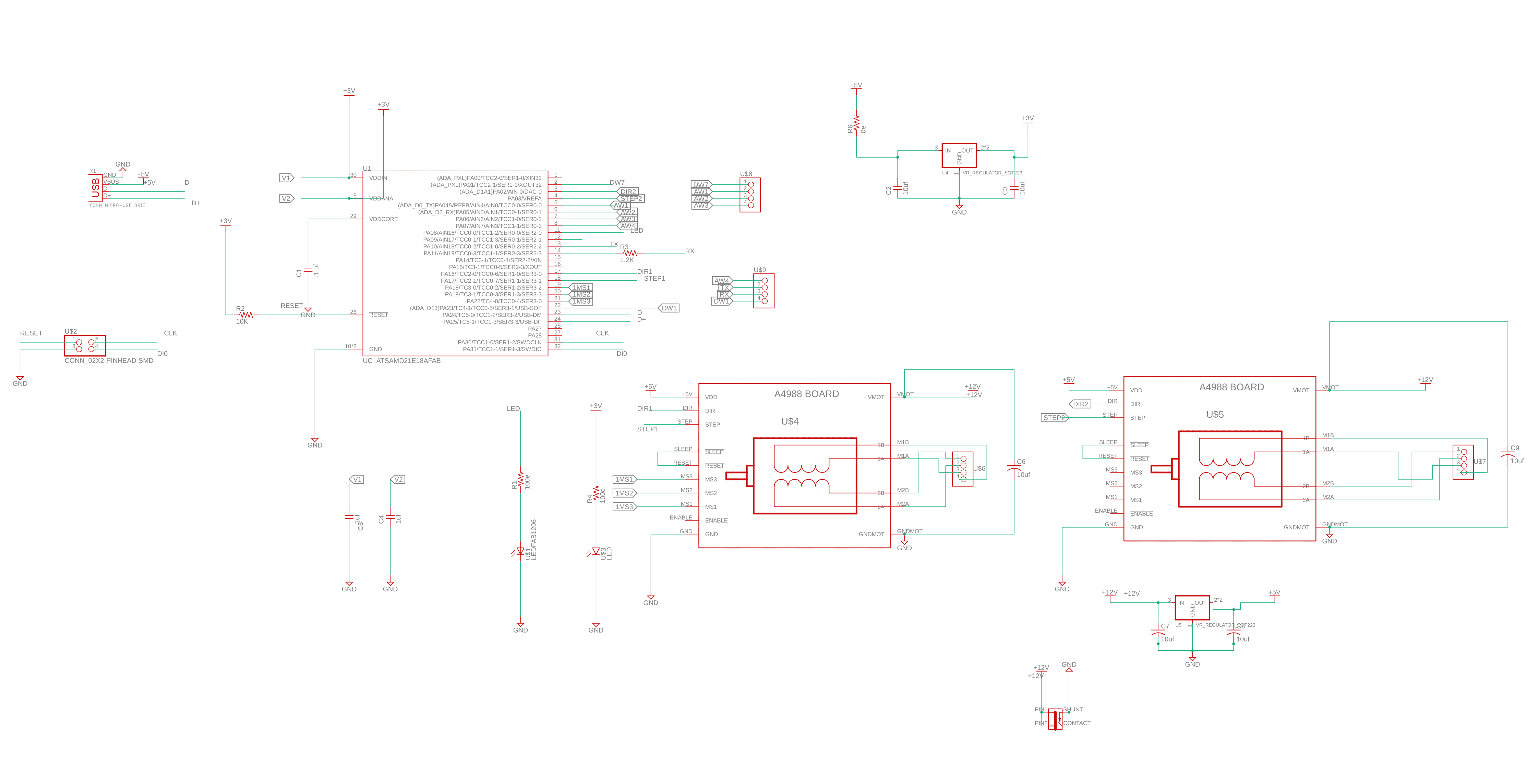
As for routing the PCB, I thought I could use an autorouter, but I guessed wrong. So manual routing it is. In the lab, we are using a bit of 16 mil thickness, so I gave 20 mils for 12 V pins, 12 mils for connections to the microchip, and 9.5 mils to connect to the microUSB. For the connections, the microUSB has the smallest thickness. And for the rest of the connections, I used 16 mil thickness.

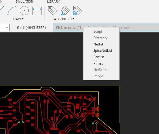
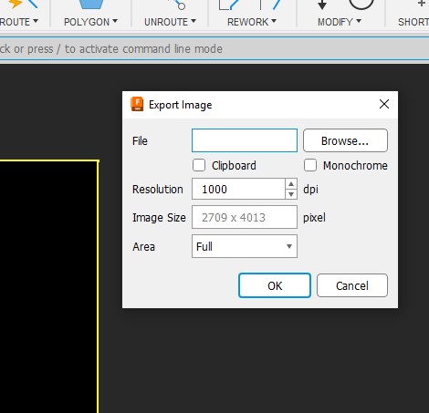
The hardest thing in Fusion 360 for me was to export the design to PNG. For all the places I searched, I couldn't find any method to export. After a long search, I found out that I can export using the command "Export" and save as PNG, and we are ready for mods.
The components that I required for this week are
| Part | Value | Device | Package | Description | CATEGORY | DESCRIPTION | MANUFACTURER | MPN | OPERATING_TEMP | PART_STATUS | PROD_ID | ROHS_COMPLIANT | SERIES | SUB-CATEGORY | THERMALLOSS | TYPE | VALUE | VOLTAGE_RATING |
| C1 | .1 uf | CAP_UNPOLARIZEDFAB | C1206FAB | |||||||||||||||
| C2 | 10uf | CAP_UNPOLARIZEDFAB | C1206FAB | |||||||||||||||
| C3 | 10uf | CAP_UNPOLARIZEDFAB | C1206FAB | |||||||||||||||
| C4 | 1uf | CAP_UNPOLARIZEDFAB | C1206FAB | |||||||||||||||
| C5 | 1uf | CAP_UNPOLARIZEDFAB | C1206FAB | |||||||||||||||
| C6 | 10uf | C_RADIAL-12.5MM-DIA | CAPRD550W60D1025H1250B | Capacitor - Generic | Capacitor | |||||||||||||
| C7 | 10uf | CAP_UNPOLARIZED2220 | C2220 | |||||||||||||||
| C8 | 10uf | CAP_UNPOLARIZED2220 | C2220 | |||||||||||||||
| C9 | 10uf | C_RADIAL-12.5MM-DIA | CAPRD550W60D1025H1250B | Capacitor - Generic | Capacitor | |||||||||||||
| J1 | CONN_JACK-2.1MM | CONN_JACK-2.1MM | PJ-002AH-SMT | SMD DC power jack PJ-002AH-SMT As found in the fablab inventory. | ||||||||||||||
| R1 | 100e | R1206FAB | R1206FAB | Resistor (US Symbol) | ||||||||||||||
| R2 | 10k | R1206W | R1206W | Resistor (US Symbol) | ||||||||||||||
| R3 | 1.2K | R1206FAB | R1206FAB | Resistor (US Symbol) | ||||||||||||||
| R4 | 100e | R1206FAB | R1206FAB | Resistor (US Symbol) | ||||||||||||||
| U$1 | LEDFAB1206 | LEDFAB1206 | LED1206FAB | LED | ||||||||||||||
| U$2 | CONN_02X2-PINHEAD-SMD | CONN_02X2-PINHEAD-SMD | 2X02SMD | |||||||||||||||
| U$3 | LED | LED | LED1206 | LED | ||||||||||||||
| U$4 | BOARD_A4988 | BOARD_A4988 | BOARD_A4988 | |||||||||||||||
| U$5 | BOARD_A4988 | BOARD_A4988 | BOARD_A4988 | |||||||||||||||
| U$6 | 1X4_SMD-MALE | 1X4_SMD-MALE | 1X4_SMD-MALE | |||||||||||||||
| U$7 | 1X4_SMD-MALE | 1X4_SMD-MALE | 1X4_SMD-MALE | |||||||||||||||
| U$8 | 1X04_SMD_FEMALE | 1X04_SMD_FEMALE | 1X04_SMD-FEMALE | |||||||||||||||
| U$9 | 1X04_SMD_FEMALE | 1X04_SMD_FEMALE | 1X04_SMD-FEMALE | |||||||||||||||
| U1 | UC_ATSAMD21E18AFAB | UC_ATSAMD21E18AFAB | TQFP-32-FAB | The SAM D21 is a series of low-power microcontrollers using the 32-bit ARM® | ||||||||||||||
| U2 | VR_REGULATOR_LM1117SOT223 | SOT223 | Voltage Regulator LM1117 | VREG-08170 | ||||||||||||||
| VR1 | NCP1117ST33T3G | NCP1117ST33T3GSOT-223 | SOT230P700X170-4 | 1.0 A Low-Dropout Positive Fixed and Adjustable Voltage Regulators | IC_Power-Management | ON Semiconductor | NCP1117ST33T3G | 0 to +125 °C | Active | RoHS3 Compliant | NCP1117, NCV1117 | Voltage Regulator | Linear | NCP1117ST33T3G | ||||
| X1 | CONN_MICRO-USB_ORIG | CONN_MICRO-USB_ORIG | DX4R005HJ5 | SMD micro USB connector as found in the fablab inventory. |
The component list probably looks weird because I used Fusion's 'Export as HTML' option for the first time.
The micro USB and the SAMD21E microchip proved to be more challenging to solder. To ensure accurate soldering and to check my soldered pins, I utilized a digital microscope. Additionally, I discovered that while soldering the IC chip and micro USB, desoldering wick proved to be an invaluable tool. If any pins accidentally solder together, using the desoldering wick to disconnect them is highly recommended.


With my experience in PCB design and soldering, the week was hard. I had done some work in the previous weeks, but this week, I insisted on doing something that would help me with my final project. Unfortunately, I realized my errors too late and was unable to fix them. Most of my errors came from my lack of knowledge. For instance, in Fusion, I edited the footprint of the microUSB, but I didn't know that I couldn't put any pins under the microUSB; if I did, it would short the circuit. I found a hack in the form of permanent marker rubbing. If permanent marker rubbing is found, the wire will not conduct for a certain voltage. It worked well for 5V, but I'm not going to risk anything else in the future.
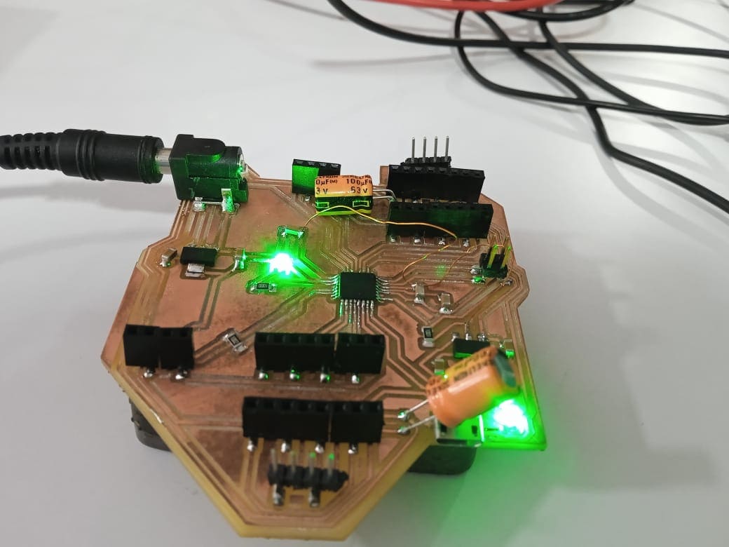
After a while of fixing my errors, I was able to successfully connect my PCB for programming. I added the official library from Fab to the Arduino IDE and programmed my chip using a programmer that we developed during a group project. To confirm successful programming, I added a power LED to check the power supply to the microchip and an internal LED to verify the programming
Everything was working fine until my previous errors caught up to me. The micro USB connection began to loosen from the board, so I decided to create a new board that included a single stepper motor and an OLED display. But I had less time and I programmed the chip using a programmer instead of a mini USB. Well, it worked.

Stepper Motor
A stepper motor is a type of electric motor that rotates in small, precise increments or steps. Unlike other types of motors that rotate continuously, stepper motors move in a controlled, precise manner, making them ideal for use in applications that require accurate positioning and speed control. Stepper motors work by receiving a series of electrical pulses, which cause the motor to rotate by a precise amount. The number of pulses received by the motor determines how far it rotates, and the rate at which the pulses are sent controls the speed of the rotation.
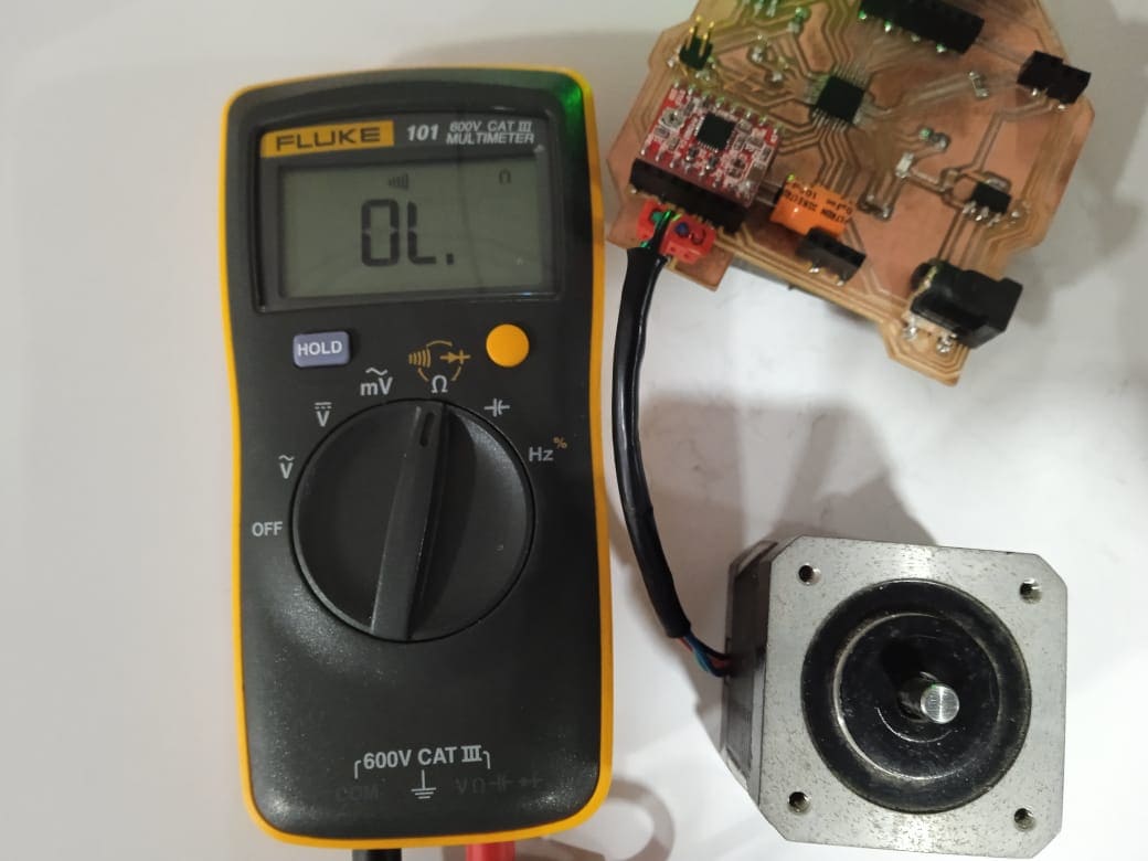
To find the connected pins of a stepper motor using a voltage continuity test, you need a multimeter. First, set the multimeter to continuity mode. Then, identify the wires that are coming out of the stepper motor. Typically, stepper motors have four or six wires, which may be of different colors or have identifying marks. Next, touch the two probes of the multimeter to any two wires of the stepper motor. If the multimeter beeps or shows a reading, it means that those two wires are connected. Note which two wires they are. Repeat this process for all the wire pairs, noting down the pairs of wires that have continuity.
The DRV8825 is a motor driver chip used to control stepper motors. Stepper motors are commonly used in robotics, 3D printers, and other precision machinery because they can move in precise increments and can maintain their position even when power is removed. The DRV8825 can control up to 2.5A of current to the stepper motor and has several features that make it useful for precision control. It uses a technique called microstepping to divide each full step into smaller steps, allowing for smoother and more precise motion. It also has built-in protection features such as overcurrent and overtemperature protection, which help prevent damage to the motor and driver.
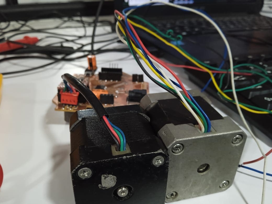
After a long time bug fixing my board, I was able to run a stepper motor, and so far I don't have any issues other than my poor designing. As for the program, I ran a simple program to rotate left and right in a loop. I am still experimenting with the motor and motor driver.
The program used was
            // Define pin connections & motor's steps per revolution
            const int dirPin = 2;
            const int stepPin = 3;
            const int stepsPerRevolution = 200;

            void setup()
            {
              // Declare pins as Outputs
              pinMode(stepPin, OUTPUT);
              pinMode(dirPin, OUTPUT);
            }
            void loop()
            {
              // Set motor direction clockwise
              digitalWrite(dirPin, HIGH);

              // Spin motor slowly
              for (int x = 0; x < stepsPerRevolution; x++)
              {
                digitalWrite(stepPin, HIGH);
                delayMicroseconds(2000);
                digitalWrite(stepPin, LOW);
                delayMicroseconds(2000);
              }
              delay(1000); // Wait a second

              // Set motor direction counterclockwise
              digitalWrite(dirPin, LOW);

              // Spin motor quickly
              for (int x = 0; x < stepsPerRevolution; x++)
              {
                digitalWrite(stepPin, HIGH);
                delayMicroseconds(1000);
                digitalWrite(stepPin, LOW);
                delayMicroseconds(1000);
              }
              delay(1000); // Wait a second
            }

            Download Design files