
5.3D Scanning and printing
Group assignment
3D printing is the process of creating a physical object from a digital 3D model. This is typically done by using a 3D printer, which adds layers of material on top of one another until the desired object is formed. The material used can vary depending on the printer, but can include plastics, metals, and even food. 3D printing is used in a variety of industries, including manufacturing, healthcare, and education.
3D scanning is the process of capturing the shape and appearance of a real-world object and creating a digital 3D model from it. This is usually done using a 3D scanner, which uses various technologies such as laser, structured light, or photogrammetry to capture the physical attributes of the object. The resulting digital model can then be used for various applications such as 3D printing, reverse engineering, and quality control.
3D printing
3D printing is a process of creating three-dimensional objects from digital models by adding material layer by layer until the final product is formed. It is also known as additive manufacturing and has gained popularity due to its ability to create complex and customized objects quickly and relatively inexpensively.
Different types of 3D printing
Reference3D printers can be categorized into one of several types of processes:

1.Vat Polymerization: liquid photopolymer is cured by light
2. Material Extrusion: molten thermoplastic is deposited through a heated nozzle
3.Powder Bed Fusion: powder particles are fused by a high-energy source
4.Material Jetting: droplets of liquid photosensitive fusing agent are deposited on a powder bed and cured by light
5.Binder Jetting: droplets of liquid binding agent are deposited on a bed of granulated materials, which are later sintered together
6.Direct Energy Deposition: molten metal simultaneously deposited and fused
7.Sheet Lamination: individual sheets of material are cut to shape and laminated together
For this week we will be concentrating mainly on FDM 3D printing . FDM printers typically use a spool of plastic filament that is fed into the printer, melted, and then deposited layer by layer to create the final object.The printer reads the G-code and begins printing the object layer by layer. The printer bed moves down by a specified distance after each layer is printed, and the extruder moves horizontally along the X and Y axes to deposit the molten filament onto the print bed. The printer may also use a cooling fan to solidify the plastic immediately after it is deposited.
Prusa slicer
DownloadPrusa Slicer is a free and open-source 3D printing software used to convert 3D models into G-code instructions for 3D printers. It is designed to work with Prusa 3D printers but is compatible with other 3D printers as well. Prusa Slicer offers many features such as customizable support structures, layer height adjustment, and infill density modification. The software also has a user-friendly interface and supports a wide range of file formats.
Setup
Prusa slicer is a very easy and friendly program. which has many many tools. which was once done manually can be automated using the software, Like splitting the bodies, and generating supports.
1.First open an sTL file by going to File << Import or drag and drop the file into the slicer
2.As for the left side tools we have
Move- to move objects along the bead
Scale-to scale objects
Rotate-to rotate the orentation of the objects
Place on face-To align objects on face
Cut-To cut objects into pieces which are too big for bed size.
Paint on supports-To generate supports manually so that the supports will be generated on the selected faces

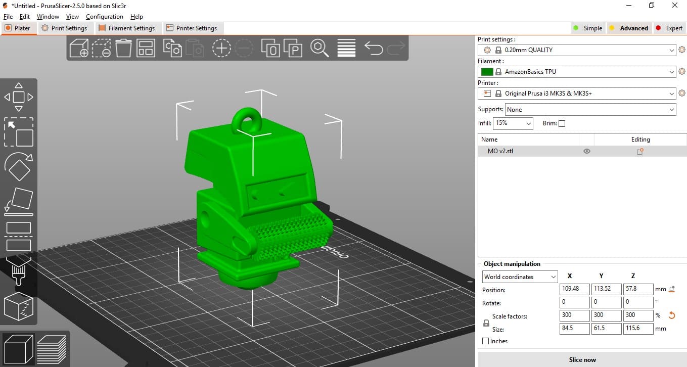
3.as for the right side we have
Print Quality-The print quality defines the distance between individual layers and the speed in which the print is going to happen the lower the quality faster the printing will be.
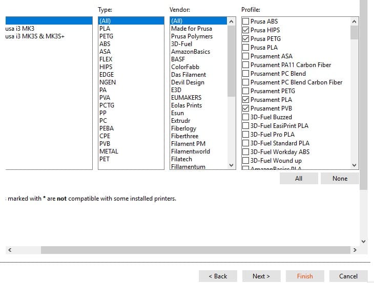
Material selection- Prusa allows a number of materials, For the week we concentrated on PLA which is a biodegradable material, HIPS and TPU which is flexible material.
Printer Selection- Then we need to add the printer which we need to print from, Prusa allows a number of printers as well as custom printers. so we can add new printers according to our needs.

Supports- Supports are necessary when creating overhanging structures otherwise the print will fail. from the menu we can select 3 options "support everywhere,None ,Support touching build plate" select according to your needs.
Brim-Brim is used to hold the object to build plate so brim is not exactly necessary but in some geometries it is necessary.
Infill-It is defined as the density of the print higher the infill higher the density, and it is valued in percentage
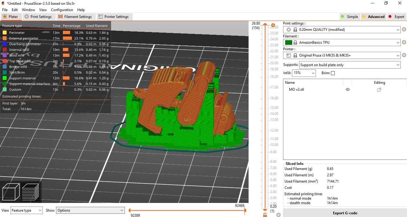
After the necessary settings are selected select slice in the bottom right corner then we can see the preview of the design. From there select generate G-code and sent it to a SD card which is ready for printer.
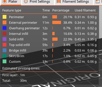
From there we can see different types of printing methods such as skirt, brim, infill ad their time in the top right corner and at the bottom left corner we can see the size of the print.

PRUSA MK3S
The MK3S features a build volume of 250 x 210 x 210 mm and can print with a variety of materials, including PLA, PETG, ABS, and more. It also comes with a removable and flexible print bed that makes it easy to remove printed objects.


Setup
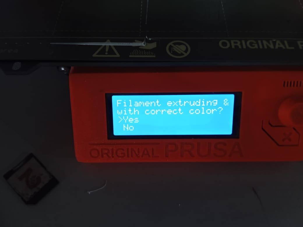
1.Loading and unloading filament-For the 3D printing week we mainly focused on printing with PlA. For Loading and unloading filament first the temperature of the nozzle need to be the same as that of the melting temperature of the material. After heating we can remove the material from the nozzle. To add new material go to settings and select add new material then put the material in the nozzle mouth. The material will be fed into the nozzle using a stepper motor. and from the window that appears select "yes" only if the color of the material extruded matches the color of the new material

2. After that we are ready to go. when the sD card is put in select the design we want to print and, well the printer can do the rest.
After uploading the design the machine has some self calibration such as auto bed levelling and self printing a line in the printer area those are some automatic features of the printer.
Auto bed leveling is a feature on the Prusa i3 MK3S that allows the printer to automatically adjust the print bed's height to ensure that the first layer of the print adheres properly. It uses a sensor to probe the print bed's surface and create a detailed 3D map of its shape, compensating for any irregularities or unevenness.
Test area printing, on the other hand, is a feature on the Prusa i3 MK3S that allows you to print a small test object in a designated area of the print bed before starting a larger print. This is useful for checking that the printer is correctly calibrated and that the first layer of the print is adhering properly.
3D design
Designing with Fusion was fun this week. I wanted to explore the possibilities of the printer, so I decided to design something fun while also testing the printer's limits. I already knew the clearance and overhanging angle from the group project, so designing parametrically with respect to those factors was enjoyable.
Although Fusion is a powerful software, I encountered more errors as I continued designing and editing midplanes. One of the problems I faced was converting components back to bodies, which required me to suppress the feature that converted bodies to components. This was an exhausting task, as there is no direct way of doing it.
Overall, despite my errors, Fusion is a powerful and user-friendly tool for designing.
M.O
As I was exploring the properties of TPU and admiring my friend's keychain, inspiration struck and I came up with the idea to create a similar keychain using this material. I set to work immediately, sketching out my design in 2D and, after only an hour, I had created a miniature version of M.O from the beloved movie Wall-E.
The design process was surprisingly easy due to M.O's simple geometry. I was able to easily manipulate his joints and add clearance to ensure he could move freely. To add an extra element of playfulness, I incorporated a movable ball at the bottom, allowing me to engage with the keychain and move him around.
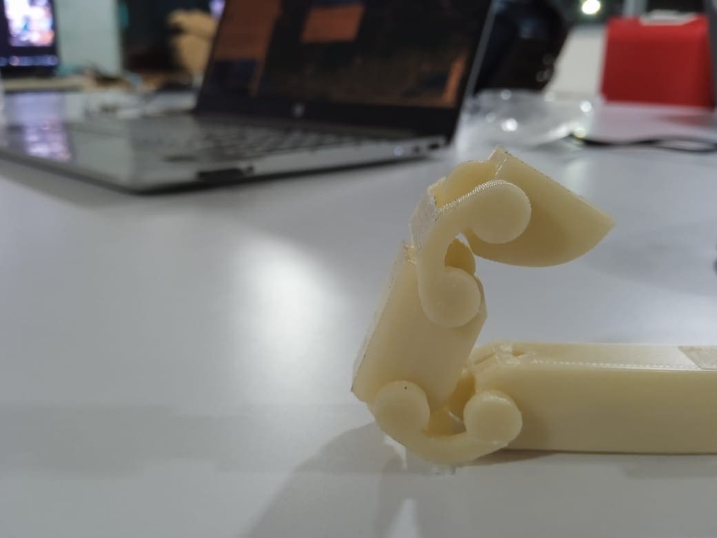
Flexibility
Flexures have always been a source of fascination for me in the realm of 3D printing. They provide the perfect solution for designing movements while also constraining the overall design. I decided to challenge myself by designing a rotational constrain that would only work in a clockwise direction, but would allow for movement with some force when turned counterclockwise. However, in order to create this design, I needed to test the flexibility of the material I was using. To do this, I designed a test object specifically to assess the flexibility of PLA. Interestingly enough, some of the printed parts didn't pass the test and ended up breaking. I continued to test different thicknesses until I was able to settle on a thickness of 0.6mm that proved to be effective for my flexure design.

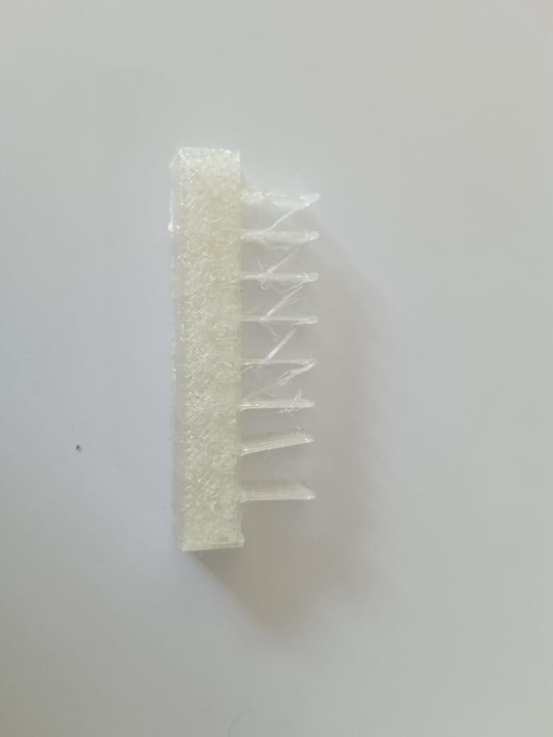
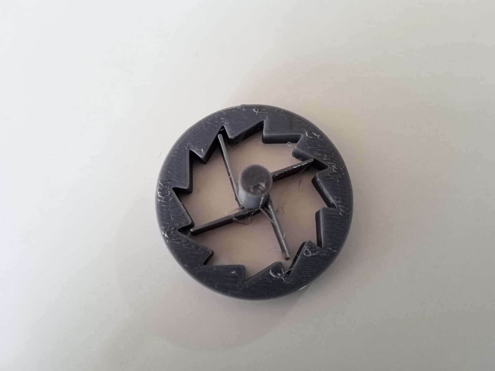
Although my design was still in its initial phase, I initially intended to create a closed structure. However, after witnessing the group assignment, I was convinced that an open type design would be more suitable.
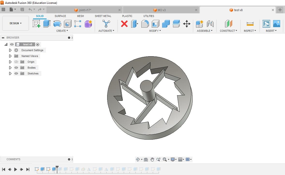
To achieve this, I created 15 outer teeth to provide a good constraining motion. As for the inner vane, I equipped it with four vanes and sufficient length to ensure flexibility and avoid breakage during testing. However, during the testing phase, I discovered that the design required more force to rotate than I had anticipated. Despite this, the design had a perfectly constraining motion in the counterclockwise direction. However, in my opinion, the design is too large.
joints
From the beginning of the week, I was determined to create a hand that had actual joints and holes in its skeleton, which could be actuated using threads. My motivation came from a video I saw on YouTube by IRIM LAB Koreatech.
With this in mind, I began working on designing the joints, making sure to include the necessary clearance for overhangs and joints. Unfortunately, the design was quite small, and as a result, I made some mistakes along the way. I soon learned that printing with supports was not optional, which added to the complexity of the project. After several attempts, I was finally able to create the design.
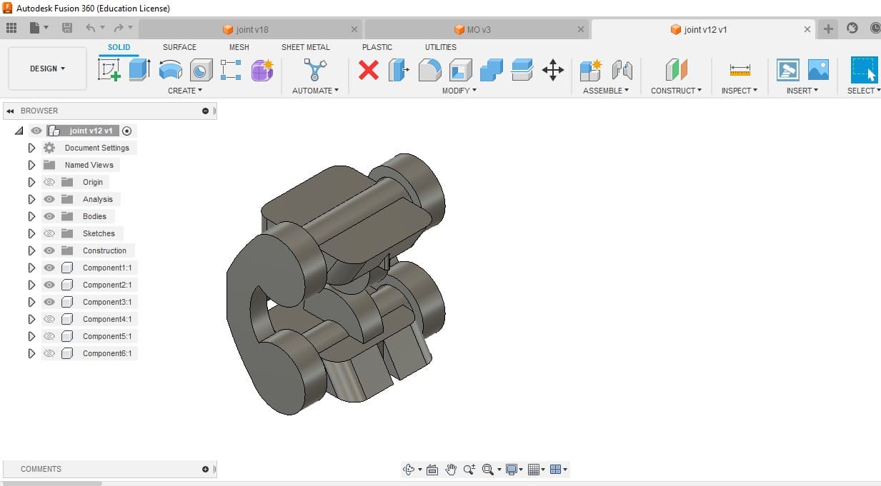
To ensure the hand had sufficient movement, I gave the joint a 120-degree range of motion by constraining its motion at the back. However, my main challenge, as mentioned earlier, was converting components back to bodies. Despite this, I remained determined to create a hand with functional joints . Well things things didn't go as I forsee.
3D printing and failures
During the 3D printing week, I dedicated a significant amount of time to reviewing various prints, but unfortunately, most of them resulted in failures. In fact, I would estimate that around 75% of the prints were unsuccessful. Nevertheless, these failures provided valuable insights into the dos and don'ts of 3D printing.

Throughout the week, I focused primarily on working with three different materials: PLA, TPU, and HIPS. Despite the high rate of failures, I found the printing process to be incredibly enjoyable. Although it's true that I wasted a considerable amount of materials, the overall experience and my proficiency in 3D printing improved significantly over the course of the week.
Materials used
PLA-PLA stands for Polylactic Acid, which is a biodegradable and compostable thermoplastic polymer. It is a popular material for 3D printing due to its ease of use and environmental sustainability. PLA is made from renewable resources such as corn starch, sugarcane, and tapioca roots, making it an eco-friendly alternative to traditional plastics.
TPU-TPU stands for Thermoplastic Polyurethane, which is a type of elastomer that is known for its flexibility, durability, and resistance to oils and abrasions. TPU is a popular material for 3D printing due to its rubber-like properties and its ability to create flexible parts and products that can withstand impact and compression
HIPS-HIPS stands for High Impact Polystyrene, which is a lightweight and durable thermoplastic material that is commonly used in 3D printing, especially in the production of support structures for printing models. HIPS is a popular material for support structures because it dissolves easily in d-limonene, a common solvent, leaving behind a clean and polished surface on the final 3D printed model.
Full control
The first thing I did on the 3D printer was to upload a randomly generated G-code from a website called Full Control. This website allows you to create unique G-code for printing, which can vary from layer-by-layer printing to a full print in the X, Y, and Z directions.
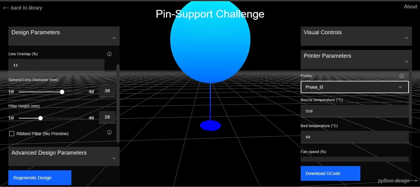
Fullcontrol.xyz provides users with the ability to choose from a range of 3D printing technologies, including FDM, SLA, and SLS, to ensure that their needs are met. Additionally, the website provides information and resources for individuals and businesses who are new to 3D printing, including tutorials, guides, and customer support. Overall, fullcontrol.xyz is a comprehensive platform for 3D printing services and solutions, catering to the needs of hobbyists, enthusiasts, and professionals alike.
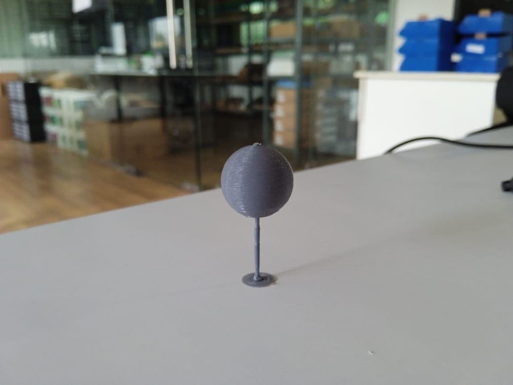
At the end I was left with something that was impossible for a conventional slicer.
M.O

The process of 3D printing M.O was actually quite enjoyable, although I did face some challenges with my first print. The initial failure occurred because I had included too many supports in the design. I had not considered the adhesion of the material, which made it extremely difficult to remove the print from the build plate and the supports. As a result, the first print was a complete failure.
However, for my second print, I learned from my mistake and reduced the number of supports. While it was still difficult to remove the supports, I was able to achieve a finished product. It was a great learning experience, and I discovered how crucial it is to balance the support structures for successful printing.
Another challenge that I encountered was with TPU, a flexible material that reacts to moisture in the air. The spool of TPU I used had trapped moisture inside, and during printing, I could hear cracking noises as the material was heated. The final product also had poor surface finish. Nevertheless, printing with TPU was fun, and I enjoyed experimenting with a rubbery material.
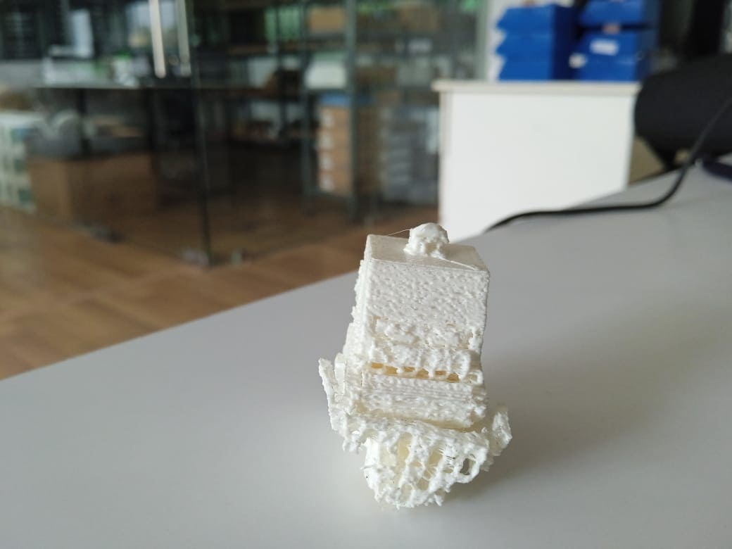
over-supported M.O with poor surface finish
Flex
Regarding the flexures, there were no unexpected issues because everything related to PLA had already been taken into consideration. However, during the design phase, I underestimated the amount of strength required for rotation, which was a design flaw on my part and not a fault of the printer
Despite this oversight, the printing process itself was completed without any issues because the design was well-planned, and the probability of failure was low. However, it became apparent that the design was not fully functional, and some modifications were required to improve its functionality.
Joints
One of the most challenging aspects of my 3D printing experiments was creating movable joints due to their small size and the designs inability to print with supports. To overcome this difficulty, I conducted several experiments with different clearances and materials. After much trial and error, I was able to make the joints functional by adjusting tolerances and simplifying the geometry. It was a rewarding experience to see my persistence pay off and achieve success in such a technically difficult task.
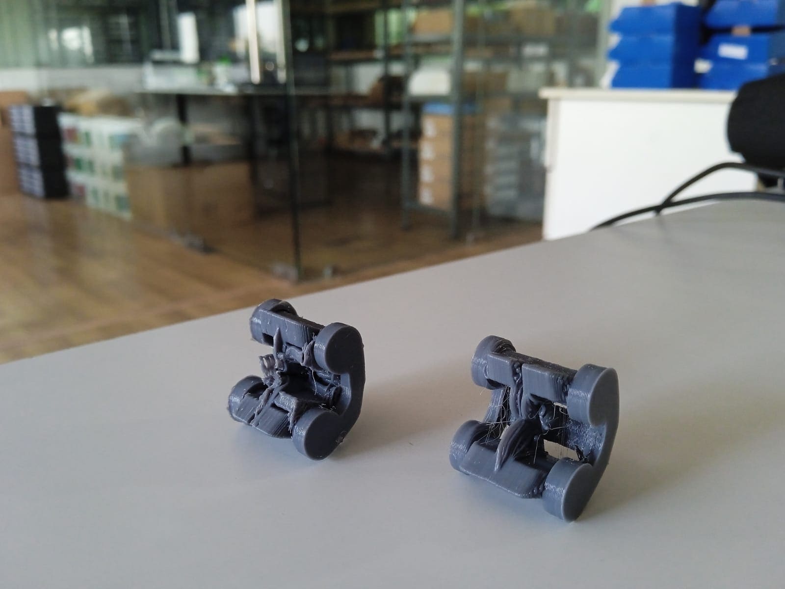
During the design process, I overlooked the size of the 3D printer. After creating and connecting the joints, I reached 75% completion and decided to check the design in the slicer program. Unfortunately, the design was too large to fit on the printer bed, which presented a challenge. I realized that the only solution was to reduce the size of the hand, perhaps to a finger.
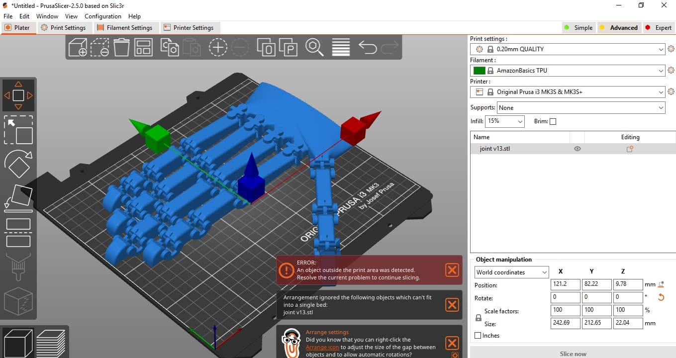
While I could have folded the joints and printed the design that way, this would have increased the likelihood of failure. Therefore, I made the decision to convert the hand design into a finger in order to fit it on the printer bed and increase the likelihood of a successful print. It was a valuable lesson in the importance of considering printer size and limitations during the design process.
For the design of the finger, I incorporated some holes to enable actuation using strings. However, due to the nature of the material used and the lack of necessary supports, the ports remained closed. To enhance the quality and enable the actualization of a biomechanical hand, I am considering printing the design using soluble supports, such as PVA. This approach will facilitate the removal of the supports, leaving the finger design with open ports, which will enable successful actuation.
3D scanning
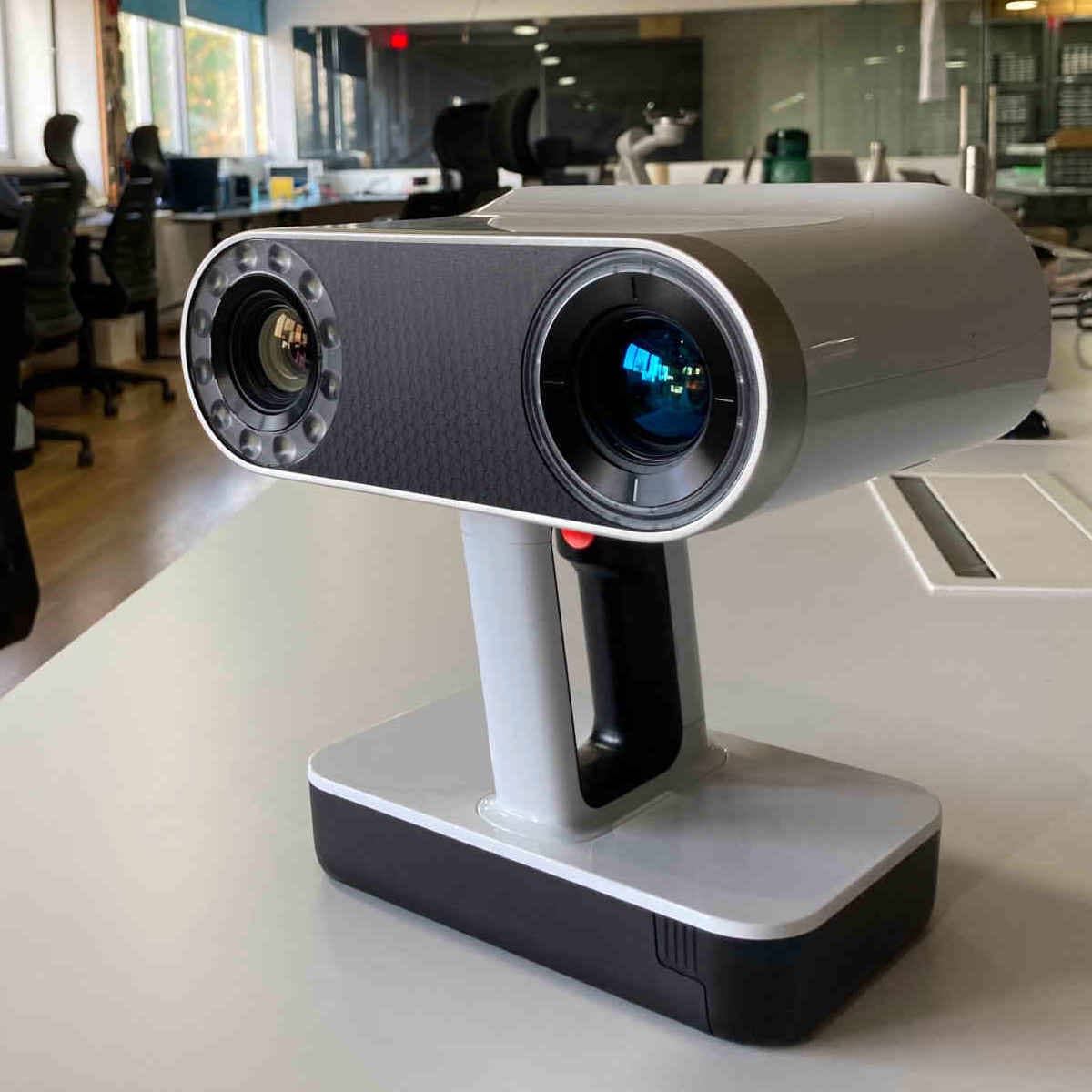
Artec Leo
Artec Leo is the only wireless and fully standalone professional 3D scanner designed to make scanning as easy and effortless as possible. With the new NVIDIA Jetson TX2 processor onboard, 5” HD built-in display and battery, it’s the ultimate all-in-one 3D scanning solution for fast, accurate, and high-quality data capture
Structured light scanning involves projecting a pattern of light onto the object and using cameras to capture the distortions in the pattern caused by the object's shape

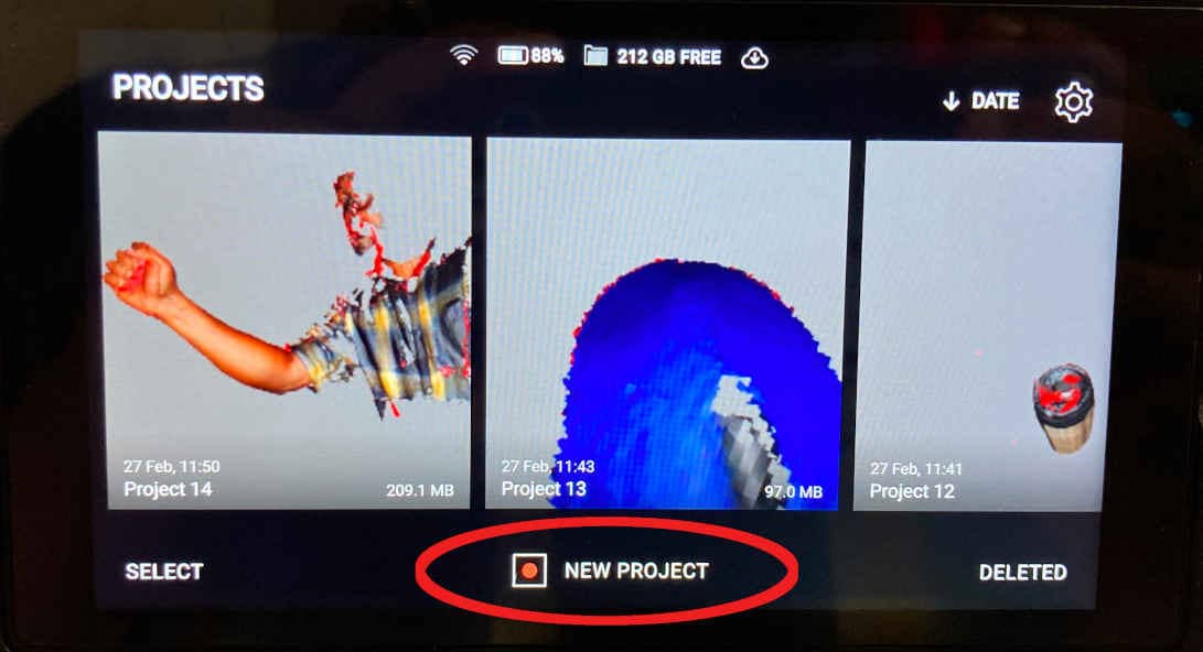
The process starts by adding a new project. After adding the new project, focus the camera on the thing you want to scan. Once the object is visible on the screen, pressing the record button will begin the scanning process. Now move all around the object to thoroughly scan it. A parabola-like action with an upward and downward wiggle can produce positive results.

Scanning
Rendering
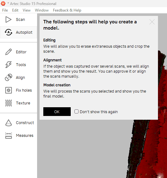
Once the scanning is finished, it must be processed before the final result is presented. Artec Studio 15 Professional software is used for that. The process is as follows
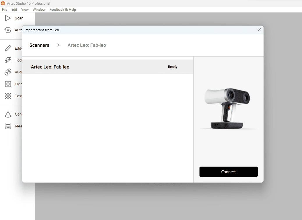
1.Import The file from the scanner. Connect the scanner to the PC and import directly from the scanner using Artec Studio.
2.Once connected, it shows the list of files saved in the machine. Select our model from list and import it to PC.

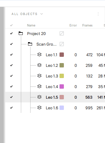
3.Once imported, the file shows different layers. This is because of the different scans made for same object.
4.Use Auto Pilot feature to merge all these into a single model. autopilot also patch holes which are small in size automatically. This can be done manually too but in here we don't need to do any heavy work.
5.Now we can edit using Editor to fix the missing features and unwanted things.
6.Use Eraser to erase unwanted objects that was captured. Use Lasso tool to select the objects and erase it.

7.Use Registration & Fusion for smoothening the object.
8.Once this is done, Use Postprocessing for filling holes & simplify mesh. We can fill holes manually also.
