
4.Embedded programming
Group Assignment
Micro Controllers
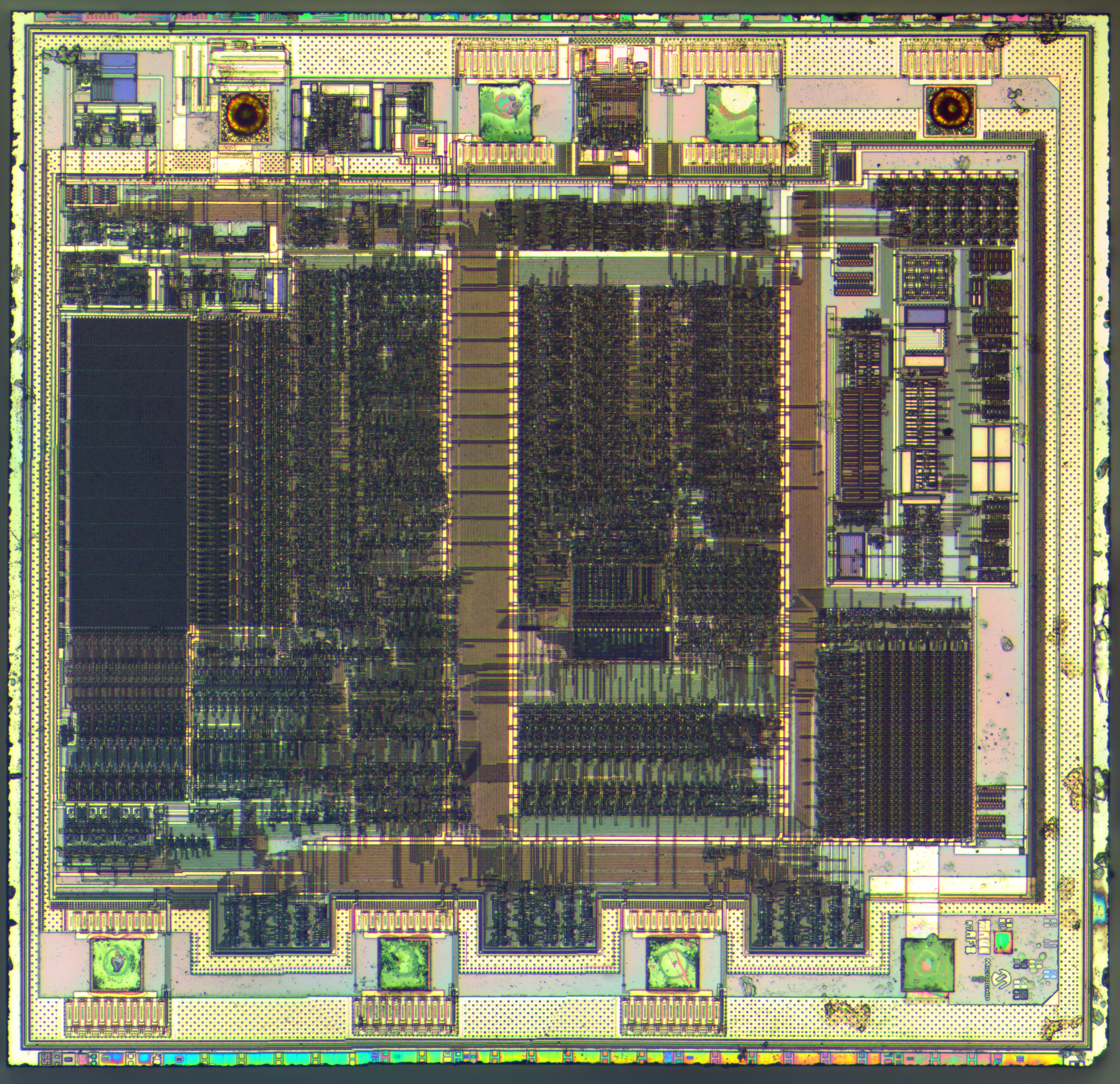
An internal Architecture Of Microchip by micro technology
Microcontrollers are a powerful and versatile tool for controlling and automating a wide range of devices and systems.Microcontrollers typically have low power consumption, small size, and low cost, making them ideal for use in devices that require a small form factor and low power consumption. They are programmed using specialized software and can be programmed to perform a wide range of functions, from simple on/off control to more complex operations such as data acquisition and processing.
Wiki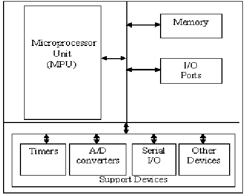
Reading Datasheets
ESP-32
The ESP32 is a dual-core system with two Harvard Architecture Xtensa LX6 CPUs. All embedded memory, external memory and peripherals are located on the data bus and/or the instruction bus of these CPUs.
Datasheet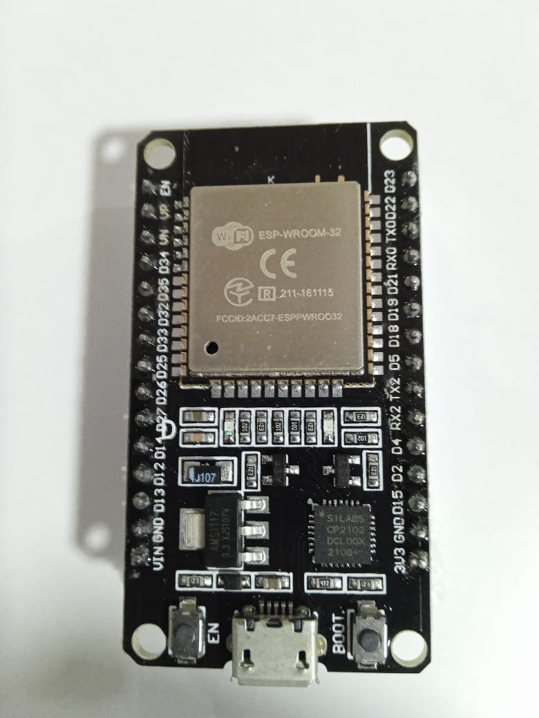

When working with the ESP32, it is essential to understand its capabilities, specifications, and limitations to design effective and efficient systems. Reading the ESP32 datasheet is a crucial first step in this process. The datasheet provides a pinout diagram and a description of each pin's function, voltage levels, and current limits. This information is crucial for designing the hardware and connecting external devices to the microcontroller.When working with assembly programming, reading the datasheet is essential to understanding the microcontroller's architecture, instruction set, and hardware peripherals.
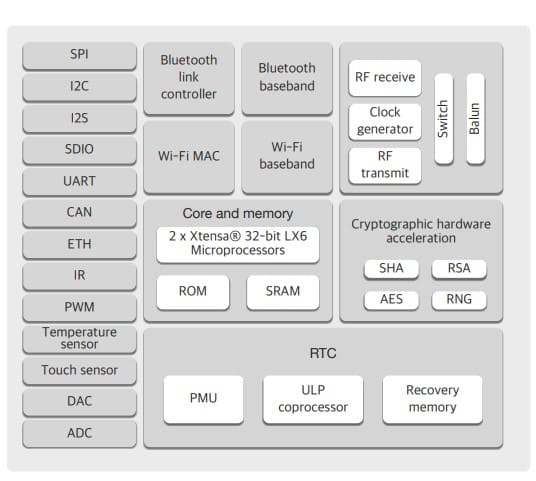
1.The ESP32 features two Tensilica Xtensa LX6 cores, which can run up to 240 MHz.
2.wi-fi connectivity with a 2.5 GHZ band with a speed of 150 mb/s
3.It has 48 ports including SPI, I2C, UART, and PWM.
4.It has a power saving mode, based on conditions it will enable deep-space mode.
External Memory
Off-chip SPI memory can be mapped into the available address space as external memory. Parts of the
embedded memory can be used as transparent cache for this external memory which
Supports up to 16 MB off-Chip SPI Flash,
Supports up to 8 MB off-Chip SPI SRAM.
STM F 303 RE
Datasheet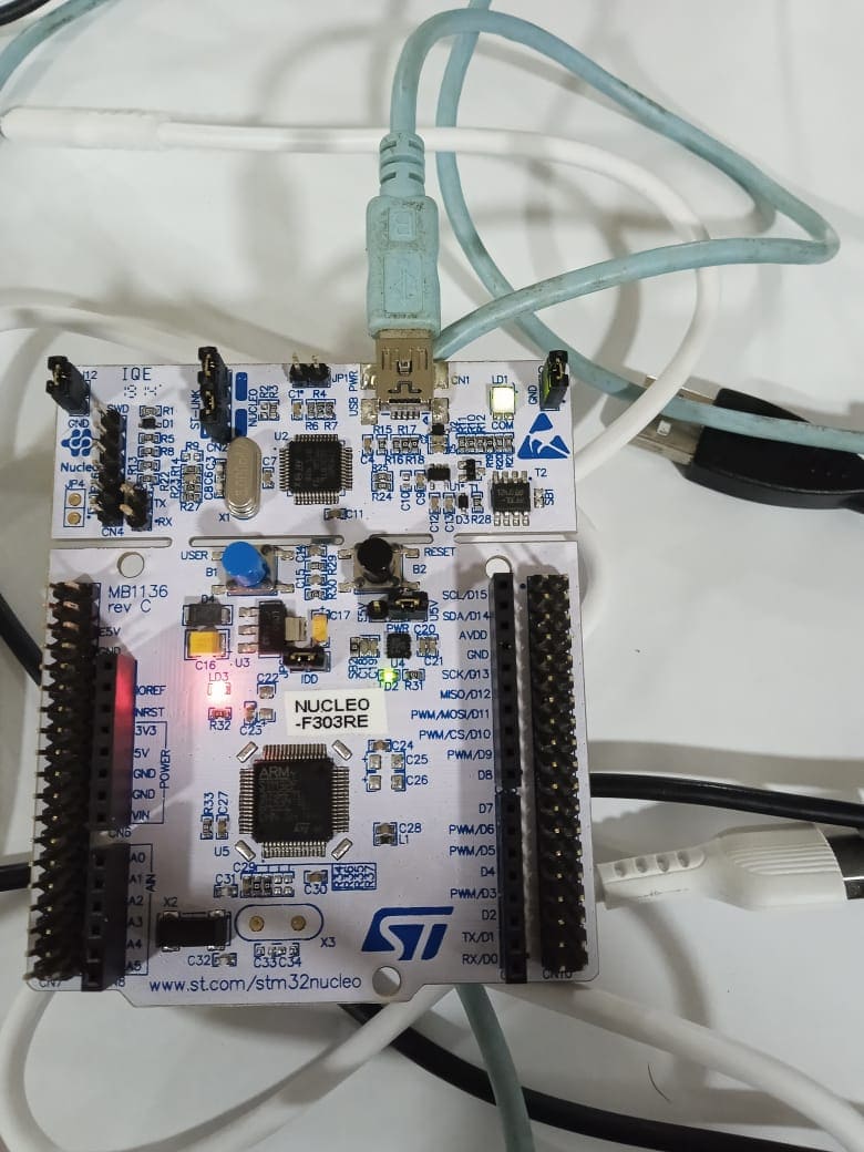
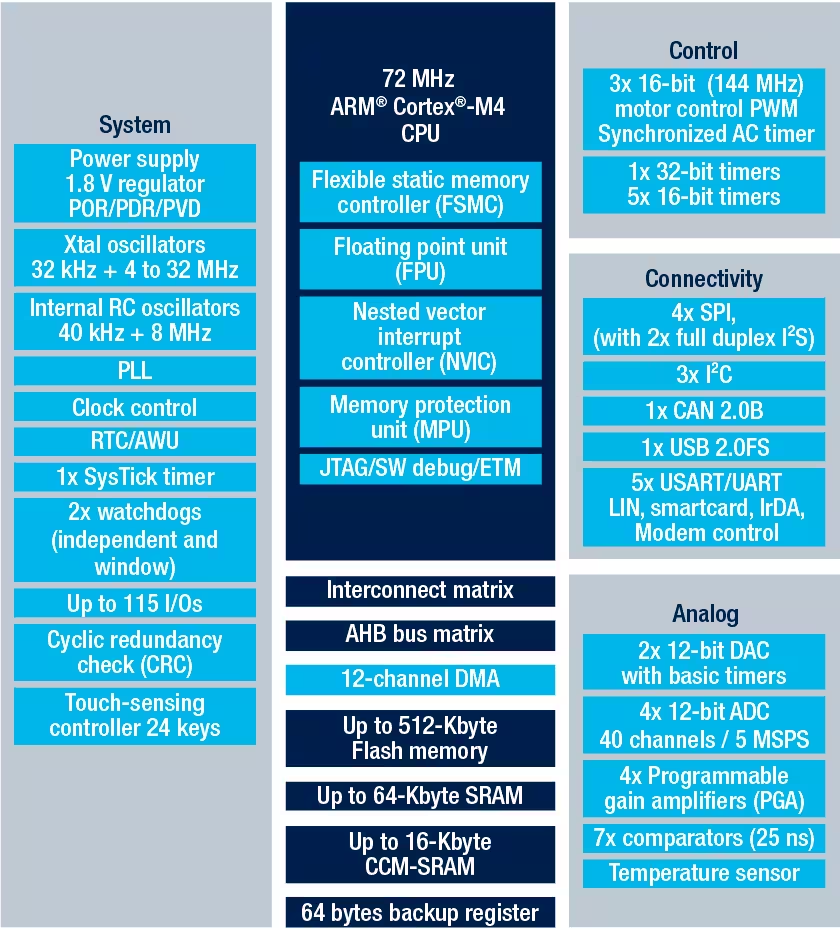
The STM32F303RE is a 32-bit microcontroller based on the Arm Cortex-M4F core.The datasheet is necessary in understanding the internal architecture and programing. STM f 303 RE is a powerful device with numerous I/O ports.

1.Core: ARM Cortex-M4 32-bit CPU with
72 MHz FPU, single-cycle multiplication and
HW division, 90 DMIPS (from CCM), DSP
instruction and MPU (memory protection unit)
2. Up to 512 Kbytes of Flash memory
64 Kbytes of SRAM
3.Clock management with 4 to 32 MHz crystal oscillator
and 32 kHz oscillator for RTC with calibration
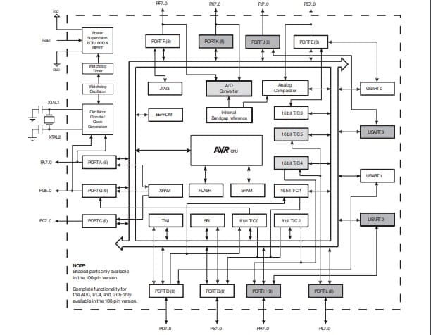
Atmega 2560
The ATmega2560 is a microcontroller chip from the AVR family, manufactured by Atmel. It is a powerful 8-bit processor with 256KB of flash memory, 8KB of SRAM, and 4KB of EEPROM. reading the ATmega2560 datasheet is essential for understanding the microcontroller's architecture, instruction set, and hardware peripherals. The datasheet provides detailed information on the microcontroller's pins, power requirements, clocks and timers, memory and storage, peripherals and interfaces, communication protocols, interrupts, and programming and debugging.

1.Advanced RISC Architecture
2.High Endurance Non-volatile Memory Segments
,64K/128K/256KBytes of In-System Self-Programmable Flash
, 4Kbytes EEPROM
, 8Kbytes Internal SRAM
, Write/Erase Cycles:10,000 Flash/100,000 EEPROM
3. Power-on Reset and Programmable Brown-out Detection
4.Ultra-Low Power Consumption
in Active Mode: 1MHz, 1.8V: 500µA
and Power-down Mode: 0.1µA at 1.8V
5.100 I/O modules with Twelve PWM Channels with Programmable Resolution from 2 to 16 Bits,Four 16-bit Timer, Output Compare Modulator so on.
6.Special Microcontroller Features include Power-on Reset and Programmable Brown-out Detection, Internal Calibrated Oscillator.
7.Six Sleep Modes: Idle, ADC Noise Reduction, Power-save, Power-down, Standby,
and Extended Standby
Arduino IDE
NOTE: Do not Misread the name of the Dev board
IDE (Integrated Development Environment) is an open source and powerful tool for programming microcontrollers. It is a user friendly software with wide range of libraries and programs
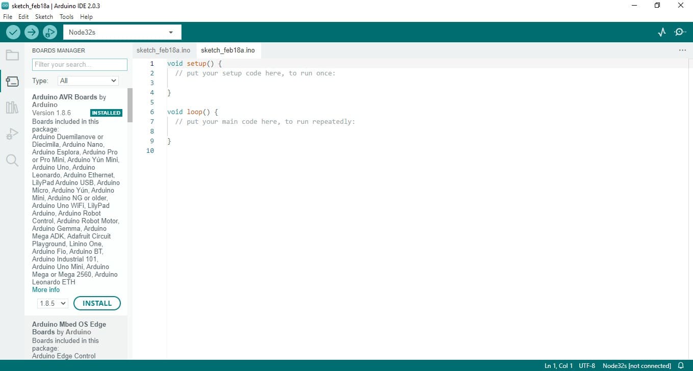
The Arduino IDE is compatible with a wide range of microcontroller boards, and it can be used to program Arduino boards, as well as other microcontrollers such as the STM32 and ESP32. Additionally, the IDE supports a variety of programming languages and can be extended with third-party libraries and plugins, making it a versatile tool for all kinds of projects.
Setup
1.To program any Board we need to have the directories for that board. To add a non-existing board in main menu go to Files< Preferences and in additional boards manage add your links using commas if you are adding multiple boards.
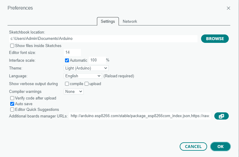
I added the URLS for my boards which are ESP 32 and STM 32
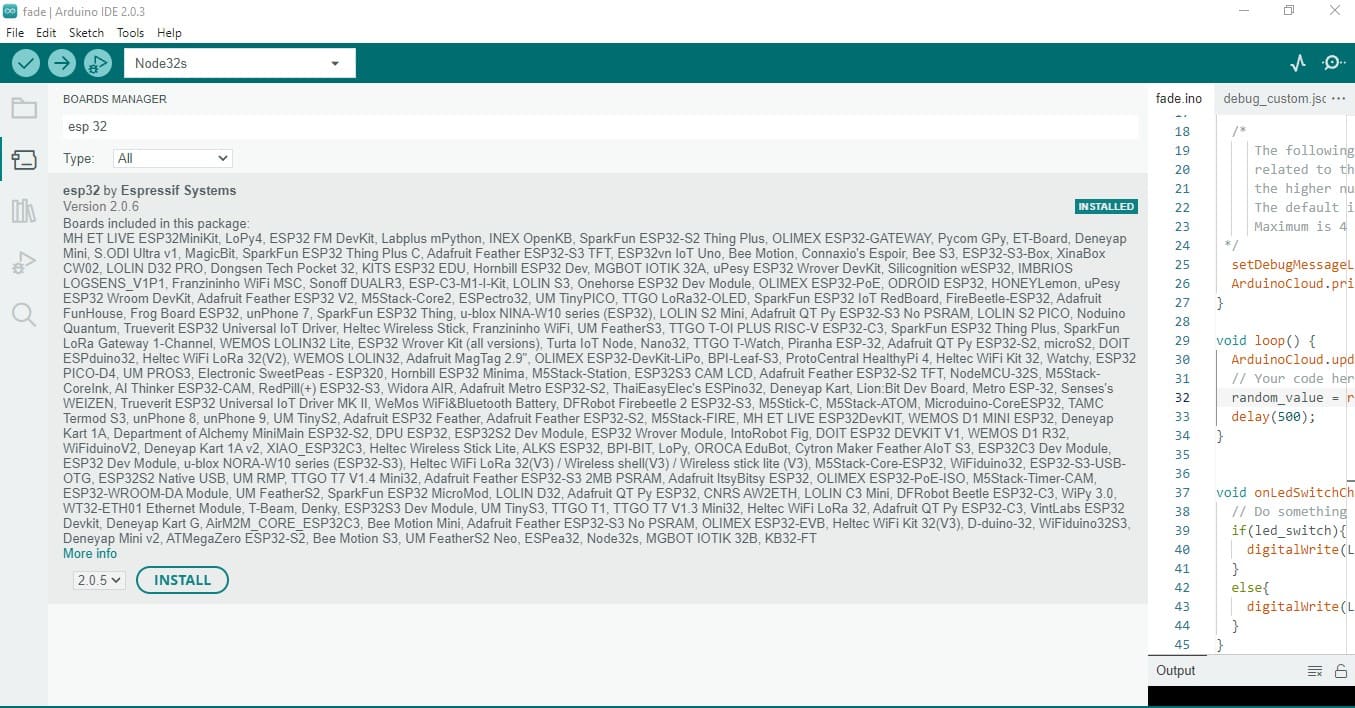
2.After adding the URL open board manager by clicking Tools << Board << Board manager from the window search for the board we need to add In my case ESP 32 and STM 32 and install the packages.
now the added boards are available in that select the your board according to the manufacturer and select the ports and start programming
after the programming verify and upload the program into the Dev board.
PWM
PWM stands for Pulse Width Modulation. It is a technique used to control the amount of power delivered to a load by rapidly switching it on and off at a specific frequency. The power delivered to the load is controlled by varying the width of the on-time (duty cycle) of the pulse, while the frequency remains constant.

The PWM frequency and duty cycle can be adjusted to optimize the performance of a system. A higher frequency provides more precise control but requires more processing power, while a lower frequency requires less processing power but may produce more noticeable flickering in the load being controlled. Additionally, the duty cycle can be adjusted to control the amount of power delivered to the load, with higher duty cycles delivering more power and lower duty cycles delivering less.
Here we use the application of pulse width modulation to control the brightness of the LED. The system allows 226 steps of voltage by using all these in a loop we can make a fading LED .
Morse code
Morse code is represented by a unique combination of dots and dashes. For example, the letter "A" is represented by a single dot followed by a dash, while the letter "B" is represented by a dash followed by three dots.Morse code can be transmitted using a variety of methods, including sound, light, or electrical signals.
In our case we wrote a program to create Morse code in the build-in LED of the Dev Board . As IDE supports a large number of boards I can upload any program into number of boards, All I need to know is the internal pin number.
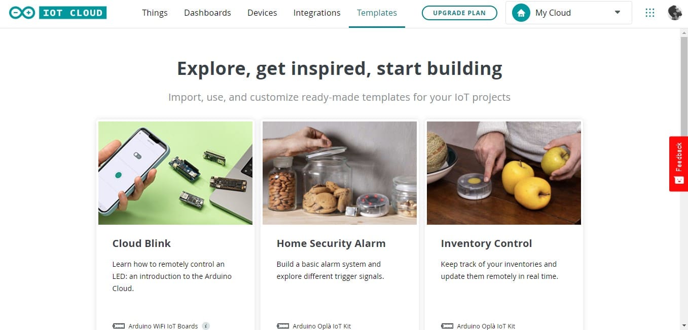
Arduino IOT Cloud
Arduino IoT Cloud is a cloud-based platform developed by Arduino, which is a popular open-source electronics platform that provides hardware and software tools for building digital devices and interactive objects.
Arduino IoT Cloud allows to connect their Arduino boards to the internet and remotely control and monitor their projects. It provides a range of features such as data management, remote monitoring, and over-the-air updates. It also includes tools to help us quickly and easily build IoT applications and connect their devices to the cloud.
Setting up
Official DocumentationTo do the cloud controlling We would require a Development board with an access to the internet in our case which is an ESP 32 DEV board. To do that I am gonna use Arduino IOT platform.
1.Go to cloud IOT by selecting The top right corner
2. Once in the cloud, click on the "Devices" tab. Then, click on the "Add device" button.Then select the type of device you want to add. As Arduino IOT allows a number DEV boards and chips.now select the board which I am using and Give it a name. Importantly choose your board correctly if not the program will not work .
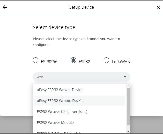
have configured a board for IOT It will appear in the list of devices.
4.Create a Thing by navigating to the "Things" tab and created devices should be available once we get there double click on the previously created device and and it will open the setup menu
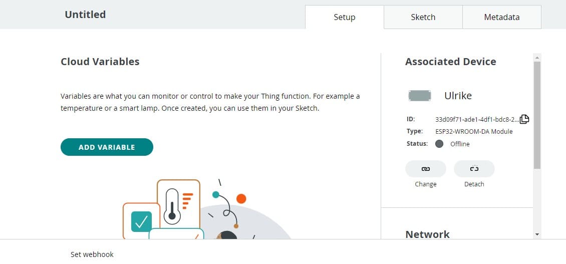
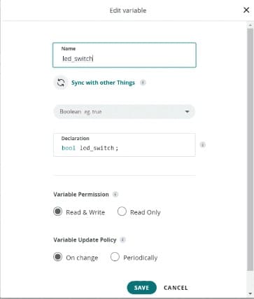
We need to add the LED switch as a variable to do that go to variables and add the led_switch variable. The data type for this variable is Boolean, the permission is read & write, and update policy is on change. Once done, click on the "Add variable" button.
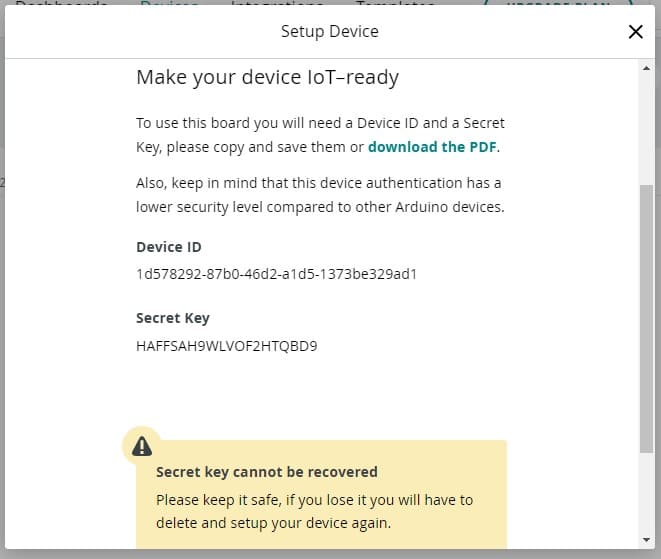
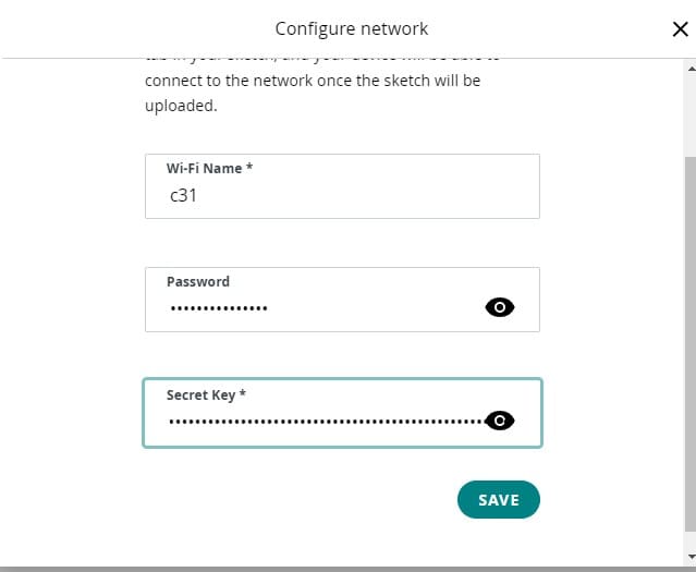
Now, we need to enter the credentials for our network, plus the secret key generated during the device configuration. First, click on the button in the"Network Section". Then, enter the network name, network password and secret key. Click "Save" when finished
The next step is to program the board. To do so, we need to go to the "Sketch" and Upload it to the board by clicking on the "Upload" button at the top left corner.
5.Now the sketch has been uploaded we can move to the final step which is creating a dashboard.First, navigate to the "Dashboards" tab. Then, click on the "Build dashboard" button.To edit the dashboard, click on the pencil icon at the top left icon, select "Things" and search for your Thing. Select it, and click on "Add widgets"
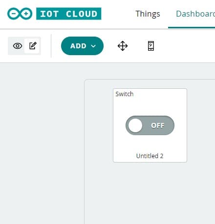
when we activate this switch, we turn ON the LED on board .
Microchip studio
DownloadMicrochip Studio, formerly known as Atmel Studio, is a free development environment that supports a wide range of Microchip microcontrollers and programming languages, including C/C++, Assembly, and Basic. It includes a powerful code editor with features like syntax highlighting, code completion, and auto-indentation to help developers write clean and efficient code.
It is a powerful an complex software which can support a number of boards and programs, highly preferred in direct port-x and assembly programs. For this software what I did was to write a simple blinking program to stimulate the specified pin out.
Setup
1.If avrdude is not installed in we need to download and install it
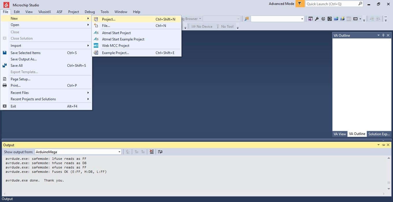
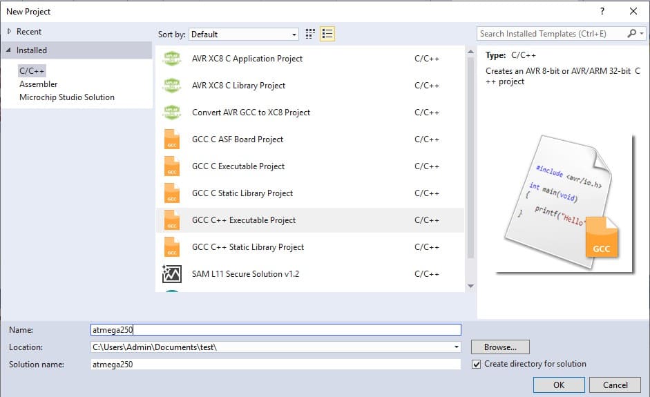
2.To start a new project go to file<< new << New project from there select the type of project you are writing can be assembly, c++ so on after that select the type of board we are using and we are set to go.

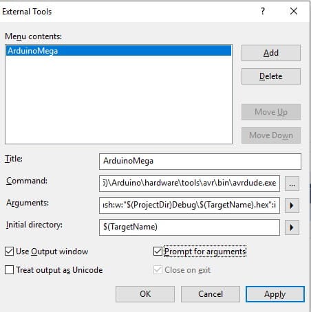
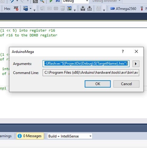
3.To create an external tool go to tools<< External toolsfrom the popup select add from there need to add command argument and initial directory as given below
command : C:\Program Files (x86)\Arduino\hardware\tools\avr\bin\avrdude.exe
Arguments: -C"C:\Program Files (x86)\Arduino\hardware\tools\avr\etc\avrdude.conf" -v -patmega2560 -cwiring -PCOM5 -b115200 -D -Uflash:w:"$(ProjectDir)Debug\$(TargetName).hex":i
Here the port number need to be changed according to the kind of port which the chip connect to in my case port5
Initial Directory : $(TargetName
after selecting the details click apply

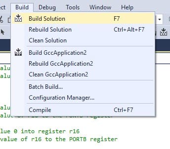
4.After finishing the program go to Build > >Build solution and compile the program
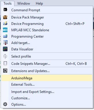
5.To upload go to tools> >Arduino mega and click ok to upload the program
Embedded C
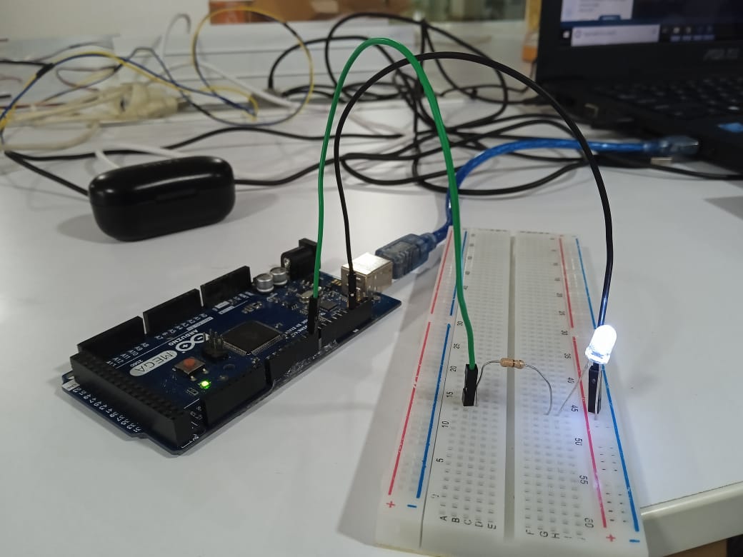
Embedded C is a programming method in which the program is run directly without any library help this is a very time consuming and hard process but faster than Arduino ide. To be frank I would never try this unless it is absolutely necessary. To do this we need to have a proper understanding between the board manufactures and microchip manufacturer which port we need to use and and code it using Boolean expression. In here we made a simple blink using Arduino Mega so we had to get the chip and board pin out.
Datasheet

Assembly
Assembly language programs are typically faster and more efficient than programs written in high-level languages, because they are executed directly by the computer's hardware without the overhead of a compiler or interpreter. Assembly language is often used in situations where performance is critical, such as in embedded systems, device drivers, or real-time applications.
However, assembly programming is also more difficult and time-consuming than high-level programming, because it requires a deeper understanding of the computer's architecture and instruction set. Assembly programmers must be able to read and write in machine language, and must have a good understanding of the computer's memory structure, input/output operations, and other low-level details.
To do the assembly programming need a good understanding of the board pin out and
Assembly programming is a very hard and time consuming one even though it is faster I would not recommend unless utmost necessity. The assembly programming is an internal programming within the chip which would require specific directories defined by the chip manufacturer and we need to specify the code of the port and directories it should move and execute the program .
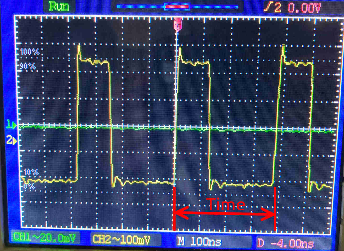
The difference in the frequency of the programming is given below.
| Language | time period (µs) | Frequency MHZ |
|---|---|---|
| Arduino IDE | 1.2 | 0.08 |
| Embedded C | 0.88 | 1.14 |
| Assembly | 0.38 | 2.63 |