3.Computer controlled cutting
Week 3 Group Assignments
Vinyl Cutting
ROLAND GX-24
A vinyl cutter uses a computer-controlled blade to cut out shapes designed using vector graphics.Mr. Rahul, our instructor already briefed about all the technical and the use cases of vinyl cutter how it cuts,blade movements,caster angle,types of blades to use,fab modules,weeding,transfer tape etc..In our lab,we have the Roland CAMM-1 Servo desktop vinyl cutter. It has a knife which is mounted on a CNC arrangement for linear motion. The knife can rotate on its axis and the bed has rollers for moving the sheet back and forth. The sheet is cut by moving the knife over it. We can set the cutting velocity and cutting force depending on the material of the sheet we are cutting.
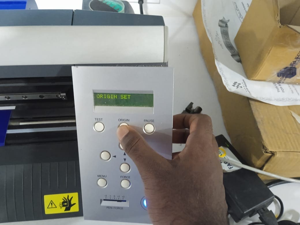
1.Turn on the machine and load the material to cut. It can be Roll, Piece, or an edge make sure that the rollers are gripping the sheet perfectly. The gripping can be done in the white markers otherwise the machine wont run.
2.Select the type of material which is sheet edge or roll. move the sheet using the arrow keys and select the cutting force for the material by doing test cuts by long pressing "Test" button.
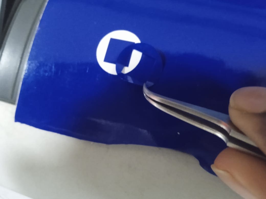
3.The example for a good cut is when the outer circle peels off without peeling the inner triangle we call it perfect cutting force. And the for the vinyl used the cutting force was 110gf.
Designing with Inkscape
Download Design FilesInkscape is a free and open-source vector graphics editor used to create vector images, primarily in the Scalable Vector Graphics format. Other formats can be imported and exported
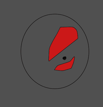
As for editing with Inkscape for the image, first, we need to change the image into a vector. To do that, we need to trace the bitmap. After creating the bitmap, create different layers and create the red part using bezier curves. Then, do an outline to align the different designs together. In my case, it is an oval shape. Finally, export the different images by turning on and off the different layers.
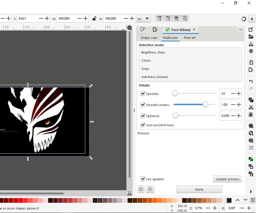

For a multilayer vinyl project I took an image and traced it's bitmap the mods allow .svg files so I created 3 different images for 3 different colors.

Actual Image

Cutting with Mods
1.Downloading A PNG file to cut
Mods is an open-source modular digital manufacturing CAM software developed by MIT’s Center for Bits and Atoms (CBA). Resulting, in a single software controlling any machine from a computer. It can communicate with Laser cutters, vinyl cutters, and CNC mills.
2.Next step is to start fab mods in locally because the machine is facing some issues with online USB port. So in order to start it locally open terminal in Fab Mods directory and run the file "start-servers" .The command is given below.
bash start-servers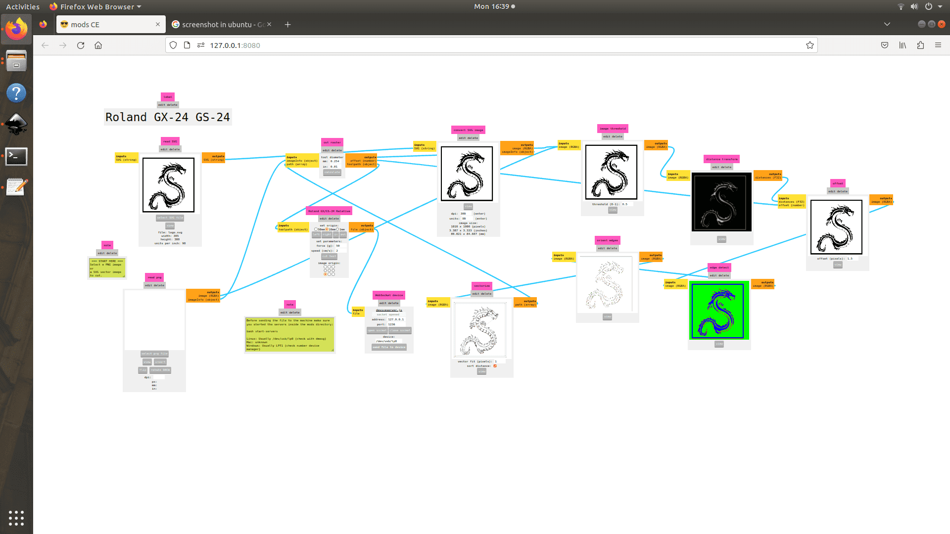
3.Select the program favorable for the machine and upload the image in .png or .svg format the size of the picture can only be modified by changing the dpi of the image. If all settings are favorable click calculate and sent it to the machine via USB port.
4.Remove and apply to a surface using a transfer sheet. In our case, which is a masking tape. When applying multiple layers on each other use tweezers for good precision.
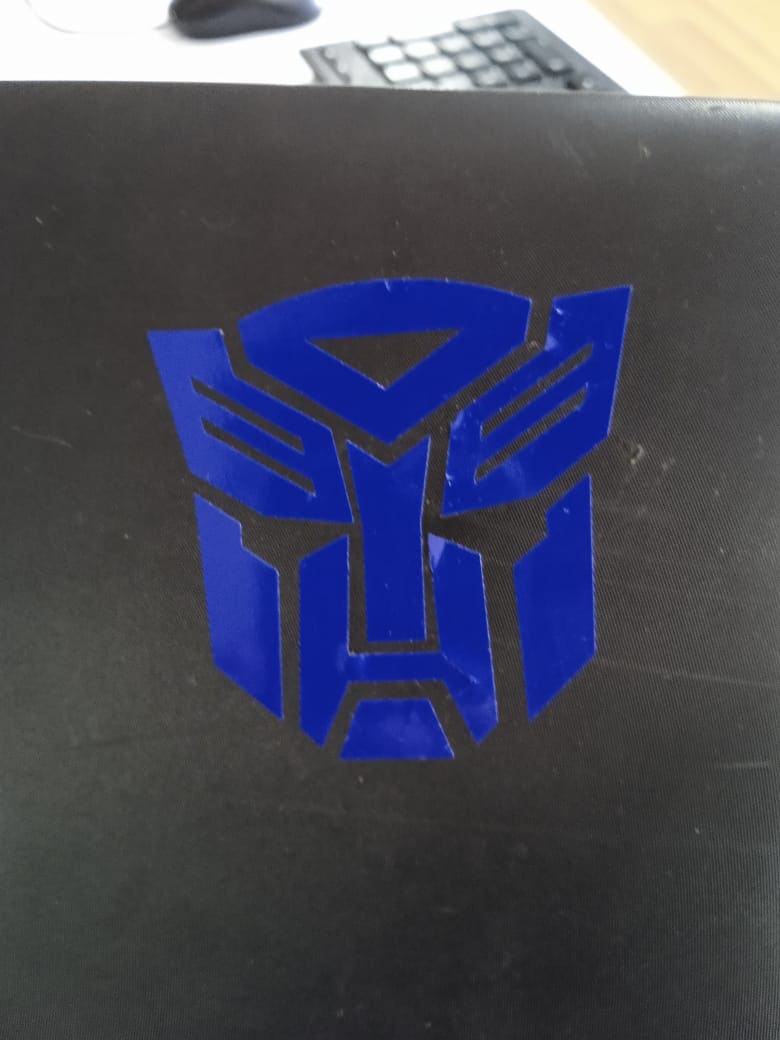
The final out after all the processes is very satisfying if it's done right ad is very fun working on multilayer vinyl.For my projects on vinyl I did 2 designs one single layer and one multilayer.

Laser Cutting
Parametric Design
As for my parametric design, I started with different polygons of different sizes and decided to go with the same length as I am trying to create a universal model for the solids. I would also require an angular constraint. So, in general, I am creating only the basic figures of my parametric model. To do that, I added a length parameter for the sides and an angular parameter for the angles for the joints. The next parameter was the thickness and kerf of the laser, which was found out using the group assignment. And at last, the design was complete and ready to cut. My designs may not look like much, but they work.
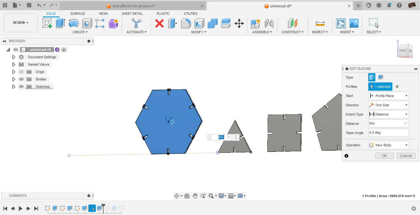
As for week 3 assignments we have to design a press fit construction kit with modifiable parameters. Fusion has an integrated parametric design I have used it before and it's good.
,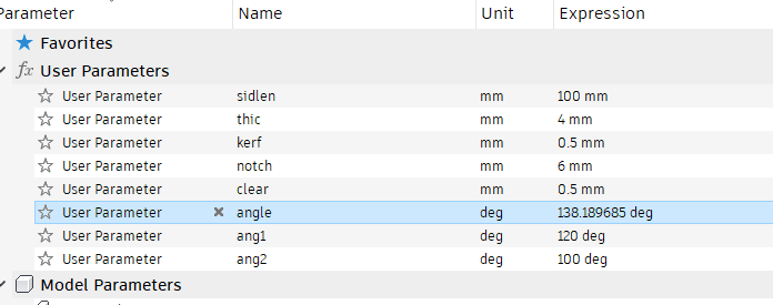
As for my project I am going with the parametric design of some Platonic and Archimedean Solids. The thing is most of them are composed of regular polygons and they only differ in their Dihedral angle so creating a joint with parametric angle so that it can be varied with the type of solid I am making.

To do different patterning on the faces I used the trace bitmap in Inkscape to convert images to svg and I can import that file and move around. The fusion doesn't allow a ratio fixing based on positioning so I had to do that parametric in inkscape and move and fix in fusion 360.
The Laser Machines
Trotec Speedy 400 Flexx Laser Cutter
There are 2 laser machines in Fab lab Kochi one is as per specification of the Fab Academy and the other one with an ultrasonic focusing. Luckily the first one is not working and the second one is also service due and the power is very low and is not enough to cut cardboard.
YOU CAN RUN BUT YOU CAN'T CUT
And the last machine we got to use from another Lab had no exhaust fans So we just did the group assignments, and Decided to do the individual assignments in an another 2D cutting machine
ZUND G3 L-2500 Digital Cutter
A Zund cutting machine is a type of digital cutting system used for cutting various materials, such as paper, cardboard, textiles, and plastics. The machine uses a computer-controlled cutting head that can move along multiple axes, allowing it to cut precise and complex shapes.
Zund cutting machines come in various models with different cutting capabilities, such as cutting, creasing, and routing.
Setting up Zund
The machine's cutting software allows users to create and edit cutting designs, which can be imported from various design software. The software also provides tools for optimizing the cutting process, such as nesting designs to minimize waste. The soft allows as to customize the manufacturing for an easy and low cost manufacturing the interface helps us to minimize wastage and maximize productivity.
1.To cut using a DXF file format first open cut editor and go to file< Add job and add the file to be cut.
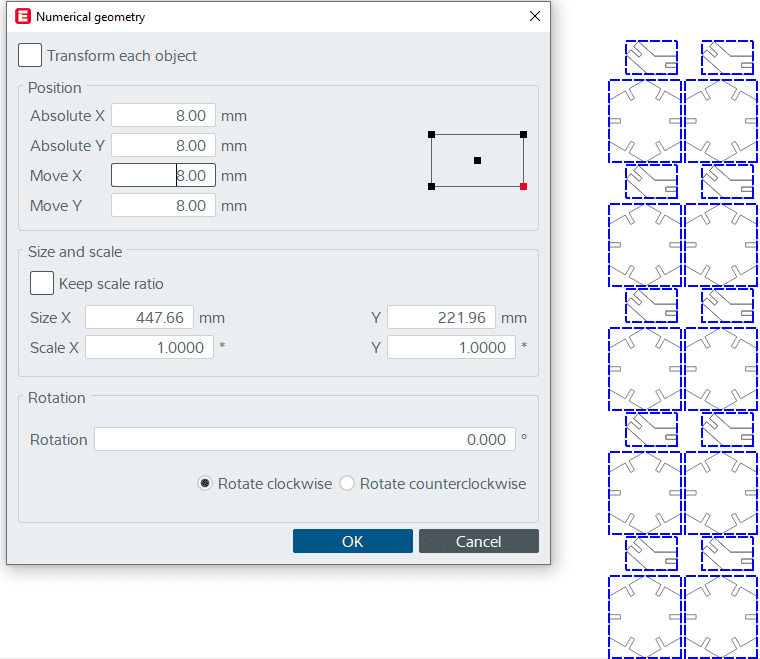
2.Now it's time to optimize the spacing between individual sketches to do that press space and and move the geometry.Also select all the figures and go to objects< numerical geometry and offset the X and Y axis from the origin to have an initial clearance when it starts cutting.
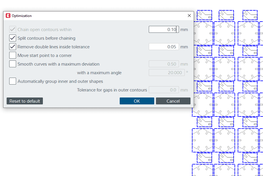
3.Optimize the design by clicking "O" or go to tools< optimize and click ok
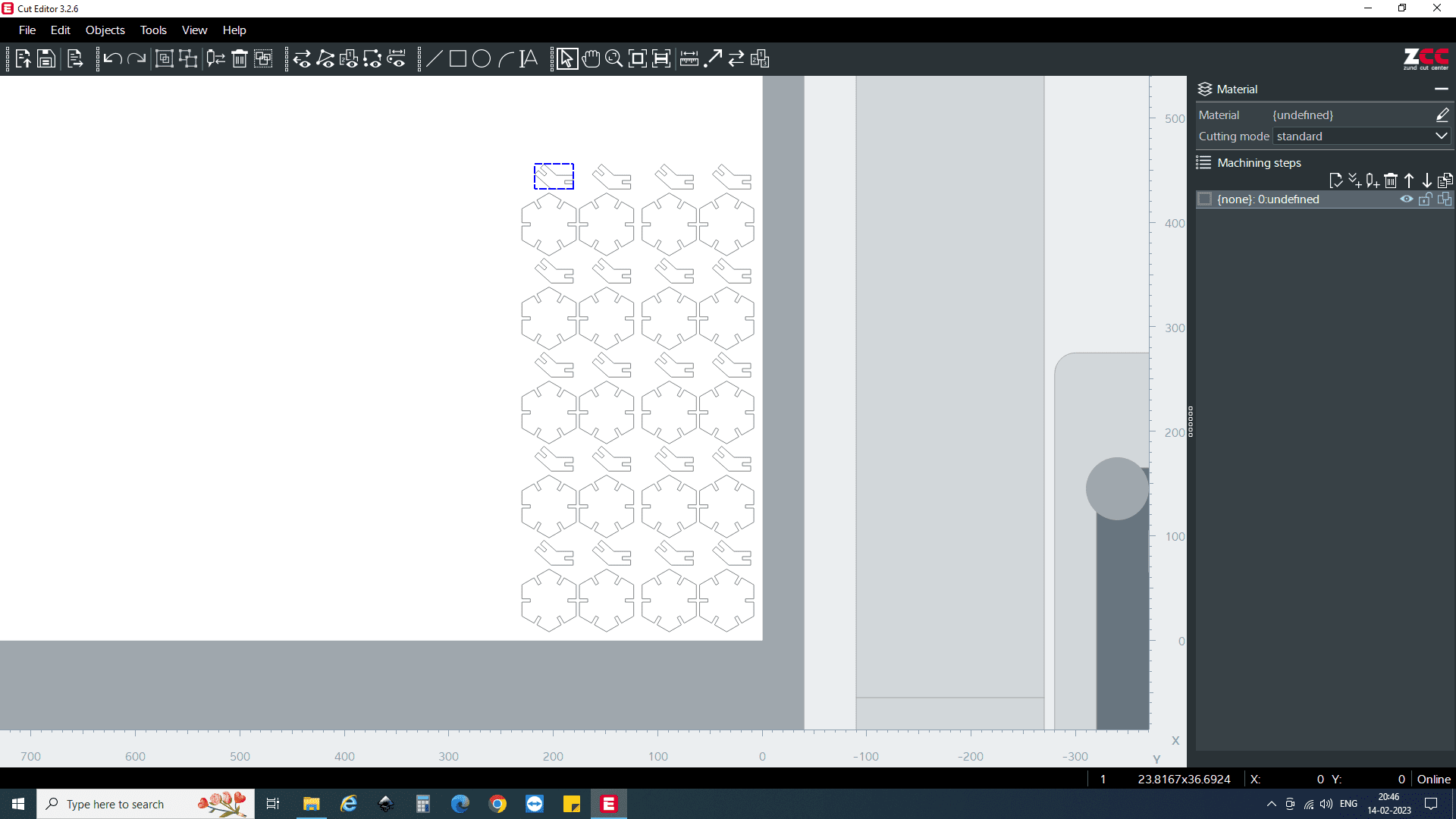
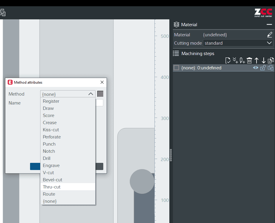
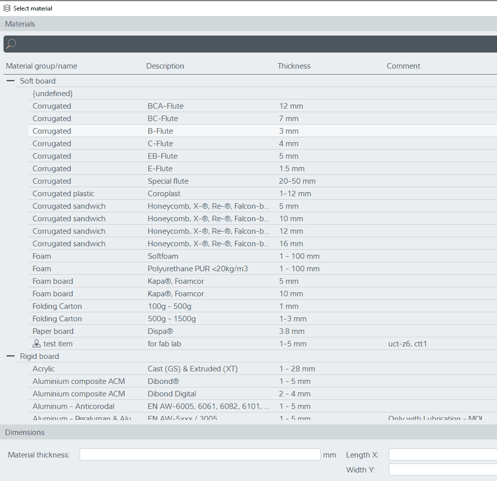
4.From the right most corner define the type of operation there are numerous types of operation available like creasing, cutting select the operation we need to do. After doing that select the material used for cutting in the right hand corner.
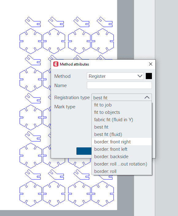
5.The machine has a scanner which scans the bed and finds the corners of the inserted sheet automatically .The job can also be done manually, So creating a Job register is not necessary but it can reduce the manual work. To do that add another step and select register then select the position you want to start cutting and for the register to happen first move up the job using the arrow mark.
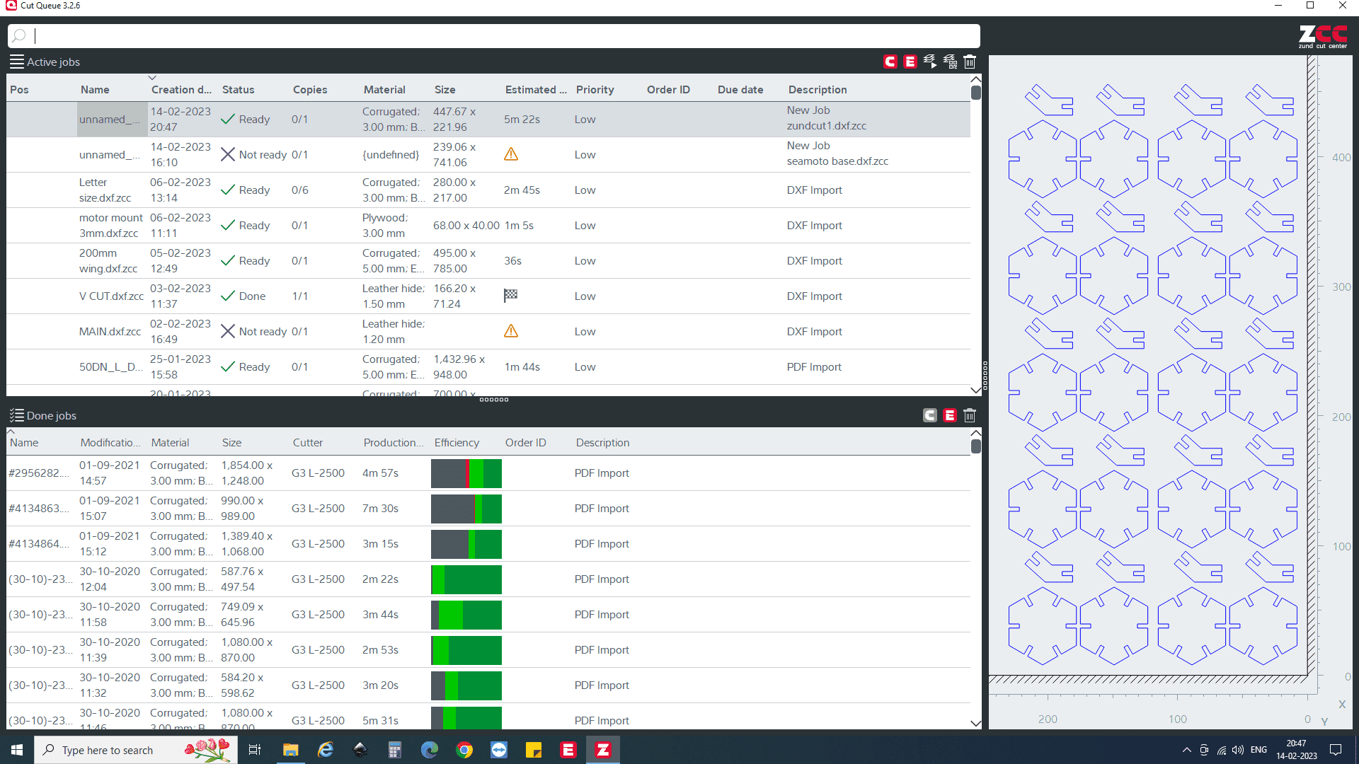
6.Click activate job and close the application then go to soft cut que and we can see the activated job in the que double click the job and open job settings
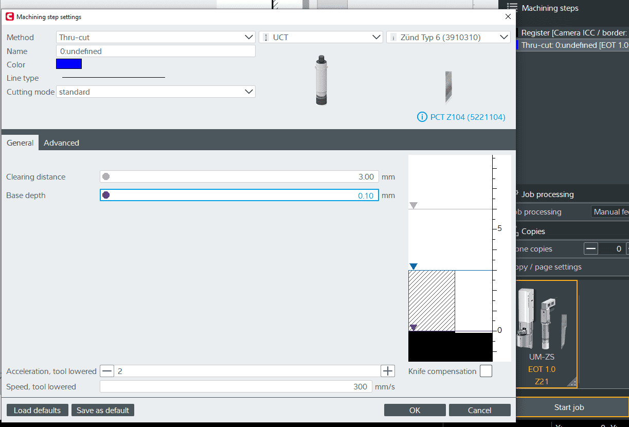
7.Here click on the tool and change the tool accordingly and also adjust the base depth so that the sheet is cut through also it doesn't cuts the Bed if all are in order Start the job.
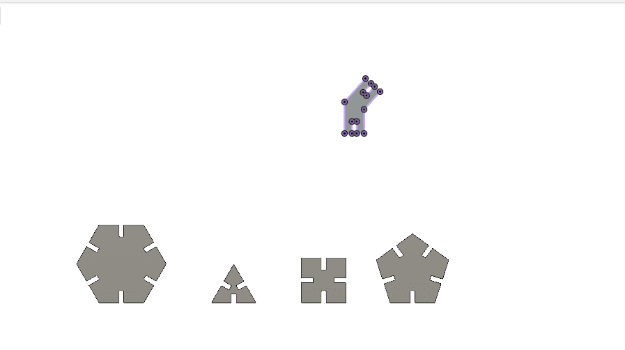
Press-fit Construction Kit
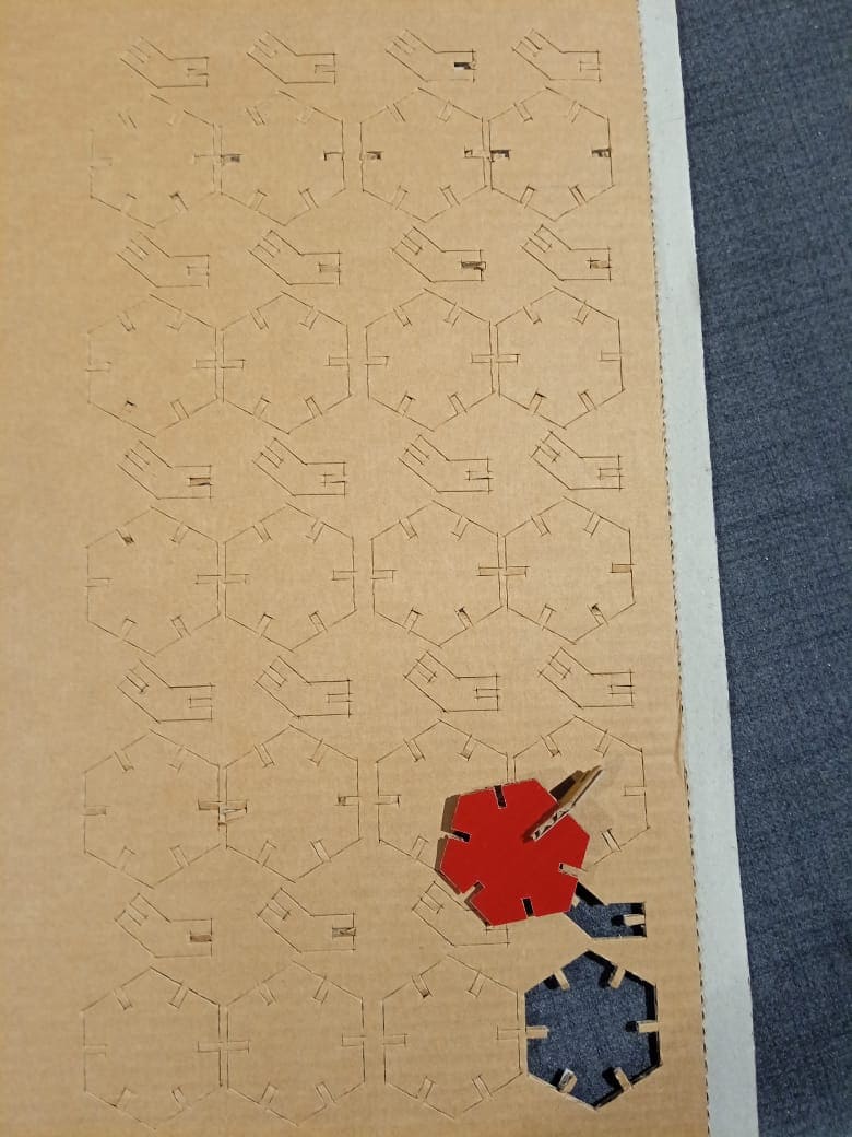
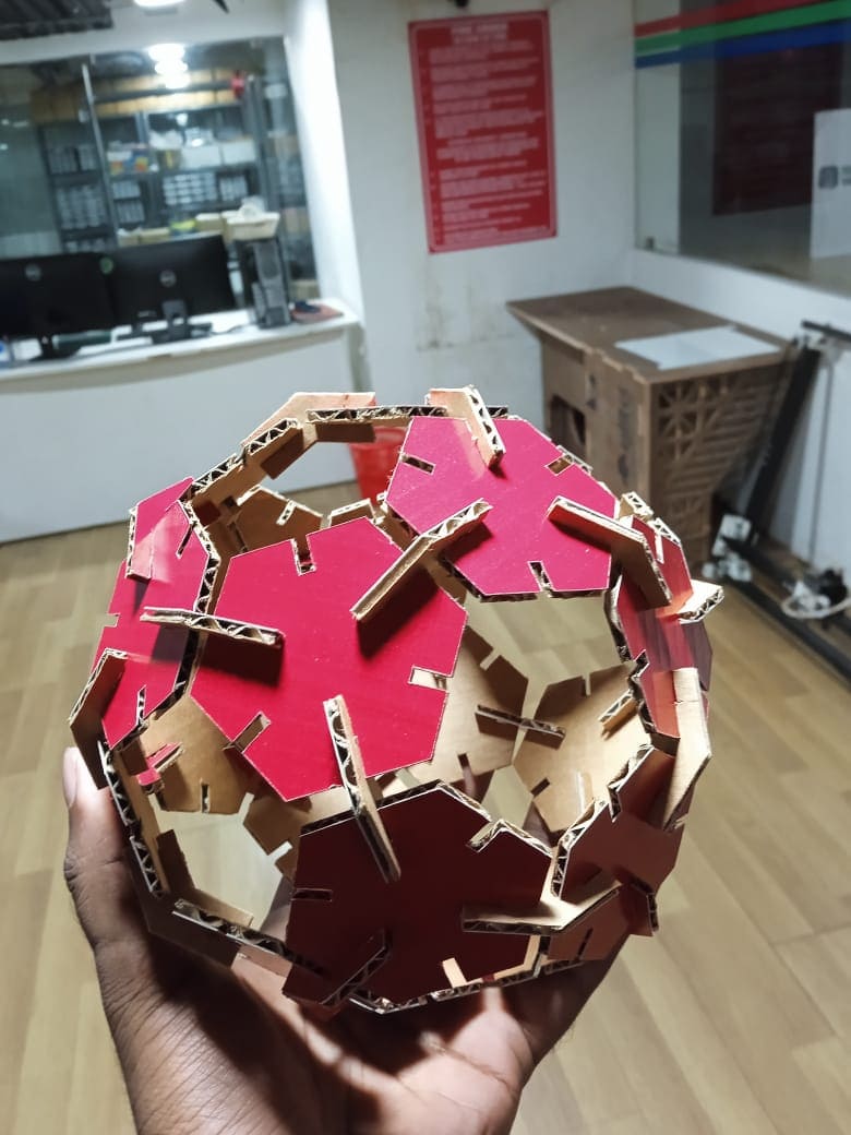
For this weeks assignment I started to design a universal file for Platonic and Archimedean solids (mentioned above), So as for cutting, due to the unavailability of the laser cutting machines we did it in the state of the art Zund. As for the assignment I decided to go with a Truncated icosahedron. This geometry consists of 20 hexagons and 12 pentagons for ease I neglected the pentagons and considered only hexagons and the dihedral angle is also given. For cutting I can edit the parameters and create any Platonic and Archimedean solids by changing the parameters of sides and angles.