
Wildcard Week -Composites
Group Assignment
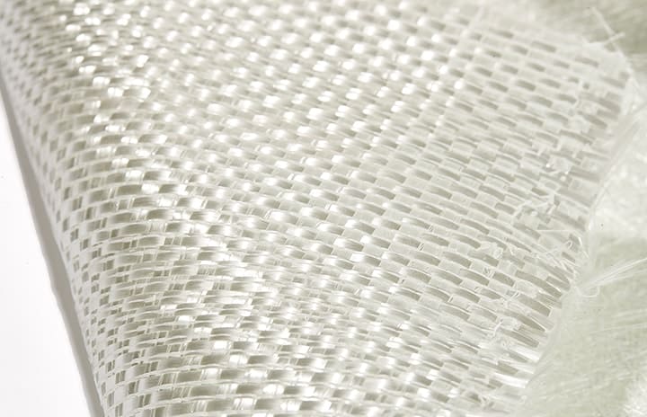
During wildcard week, I had the freedom to choose any assignment I wanted. Being someone who loves experimenting and trying new things, I selected the composite assignment that involved working with fiberglass material. It was more of a personal challenge that I wanted to take on for fun. As I delved deeper into the project, I began to brainstorm different ideas and eventually settled on making morphing wings. This was an ambitious project that required a compliant mechanism in a single mold. I wasn't sure if I could pull it off, but I was excited to try.
Morphing wings
Morphing wings are wings that can change their shape during flight. These wings have the ability to alter their geometry, such as their span, chord, and twist, in response to changing flight conditions. The goal of using morphing wings is to improve aircraft performance, efficiency, and safety. By changing the wing shape, the aircraft can adapt to different flight conditions, such as takeoff, cruising, and landing, and achieve optimal aerodynamic performance.
Morphing wings can be designed using different technologies, such as shape-memory alloys, electroactive polymers, and compliant mechanisms. Compliant mechanisms are a popular choice for creating morphing wings because they can be manufactured as a single piece, eliminating the need for complex joints and actuators. Compliant mechanisms use the elasticity of materials to create motion, which makes them lightweight, reliable, and easy to maintain.

In composite manufacturing using fiberglass, the innovative idea revolves around creating a flexible morphing wing. The key lies in employing compliant mechanisms that enable the wing to undergo transformative movements. To introduce flexibility, a clever technique is employed where resin is strategically moved from specific sections of the design. This is achieved by incorporating notches into the mold during the manufacturing process. As a result, certain areas of the wing possess less resin, allowing them to be flexible, while other regions remain relatively rigid. This combination of resin distribution provides the desired morphing capability, enabling the wing to adapt to different flight conditions with enhanced maneuverability and efficiency.
Design
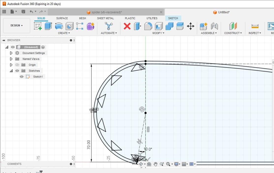
For my individual assignment, the objective was to design and fabricate a morphing wing using Fusion 360 as my primary design software. To begin, I created an aerodynamic shape for the wing, specifically an airfoil with dimensions of 80 mm in height, 350 mm in length, and 105 mm in width. This served as the foundation for testing the morphing capabilities of the wing design.
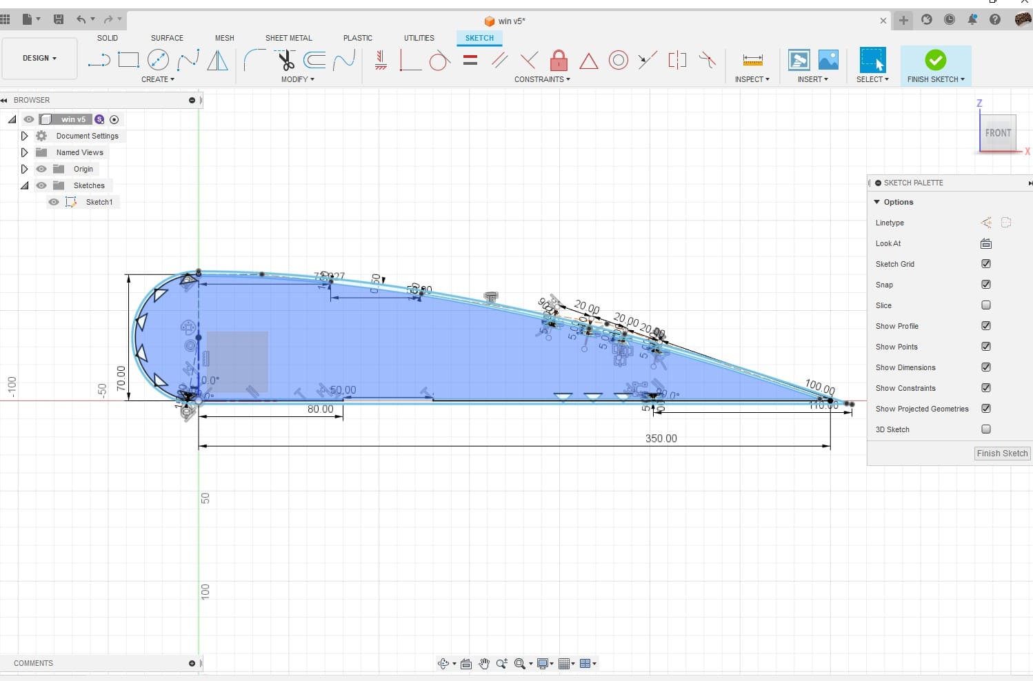
During the design phase, I focused on incorporating the necessary elements for a morphing wing and compliant mechanisms. The aim was to develop a wing design that could generate lift and drag efficiently. While calculations were not included in the design process, careful consideration was given to the overall shape and structure to achieve the desired aerodynamic characteristics.
To proceed with the manufacturing process, I created a 3-piece mold. The core mold featured protrusions strategically placed to enhance flexibility by redistributing the resin in specific areas. These protrusions were essential in facilitating the morphing of the wing. By allowing the resin to move from certain parts, the wing would gain the necessary flexibility for its intended function.
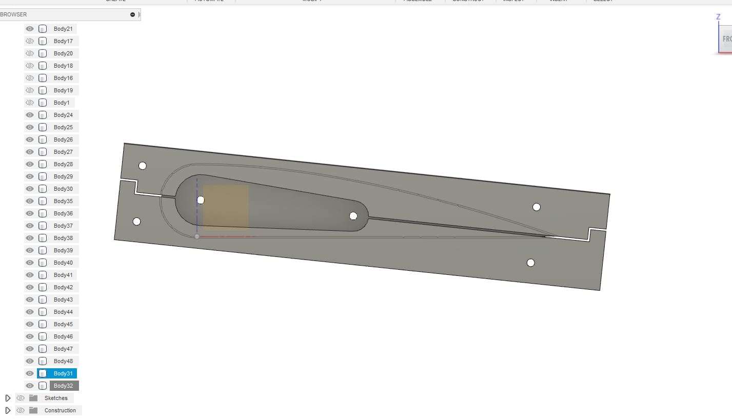
For the mold construction, I decided to use 15 mm plywood, which was suitable for the milling process. To simplify production, I designed the mold in a way that enabled 2D milling. The individual components could be easily milled and subsequently assembled using screws, ensuring a robust and reliable mold structure.
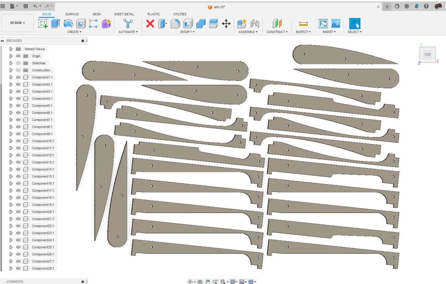
Before proceeding with the milling process, I exported the finalized design as a DXF file, making it compatible with the shopbot machinery. Additionally, I made sure to account for clearance issues by adjusting the design to achieve precise fitting between the different mold components.
Milling
To bring my cool individual assignment to life, I fired up the Shopbot milling machine. With the DXF file I exported from Fusion 360, I fed it to the Shopbot software and let the machine work its magic. This CNC beast is known for its precision and versatility, making it the perfect choice for this part of the process.
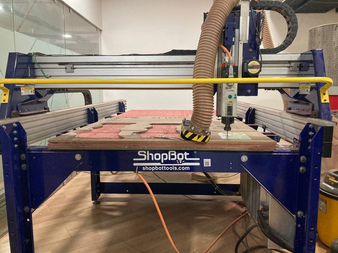
When it came to the computer-aided manufacturing (CAM) process, I turned to the V-Carve software. It helped me generate the toolpaths and optimize everything for the milling process. With V-Carve and the Shopbot, milling was a breeze, and I didn't run into any major hiccups or problems along the way.
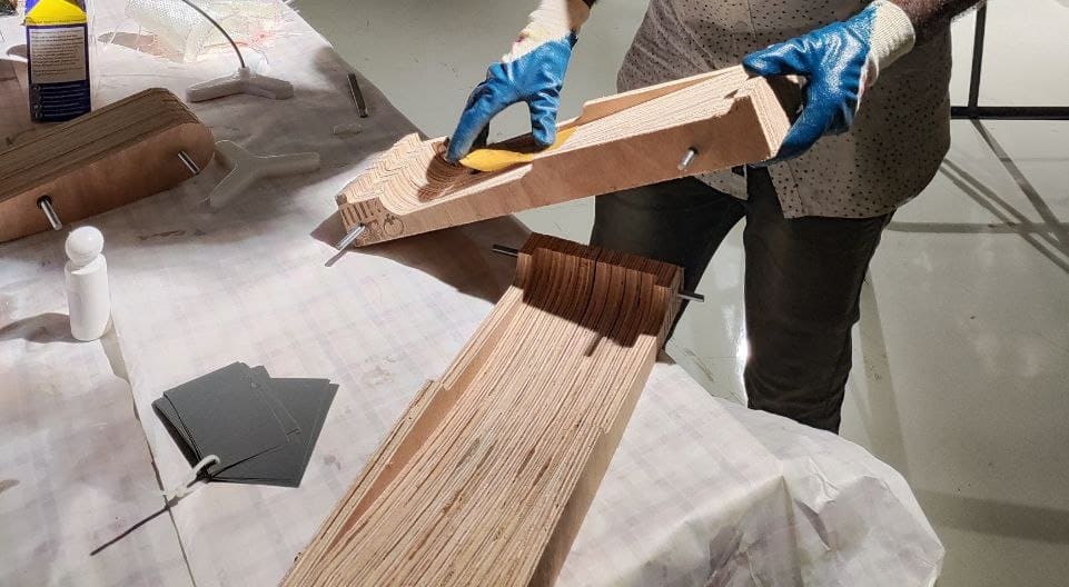
Once the milling was done, I had all the pieces for my mold. The machine did its thing flawlessly, carving out the components from the 15 mm plywood like a boss. The pieces fit together like a jigsaw puzzle, and all it took was a few screws to assemble them. It was a breeze to put everything together, thanks to the precise measurements and tight tolerances achieved during milling.

After the assembly, I gave the surface a once-over to smooth out any little bumps or imperfections caused by the milling process. I used sandpaper to make it nice and neat, but I didn't go overboard because sanding can be a bit tricky to control. With just a bit of finishing work, the mold was looking solid and ready for the next steps.
For the assembly, I grabbed my trusty screwdriver and a mechanized drill. With those handy tools, I secured the pieces together, ensuring the mold was nice and sturdy. It was important to have a solid foundation for the rest of the assignment.
Fabrication
Due to the aforementioned issues, I decided not to use the Zund machine for cutting the fiberglass. Instead, I utilized a cardboard piece as a measuring tool to determine the required amount of fiberglass to be cut. To ensure precise cutting, I opted for scissors, as they provided greater control. Using the cut cardboard as a template, I marked the pieces to be cut from the fiberglass.


In the process of fabricating the flex wing for my assignment, I encountered certain challenges during the composite release from the wooden mold. To overcome this, I opted for plastic wrapping as a mold release agent. I used double-sided tape to securely attach the plastic wrap to the mold surface and then employed a heat gun for heat shrinking. Although the heat shrinking process didn't go as planned, Jogin Francis assured me that the weight of the material would aid in achieving the desired outcome.


The layering pattern I used was as follows: first, I layered the sheet so that the ends of each layer would meet without overlapping. Additionally, I made sure that the ends did not meet at the exact same point, as I wanted to avoid any structural instability caused by the edges meeting at a single point. With that in mind, I proceeded to casting.

In order to maintain a clean work surface, I took the plastic wrap and wrapped it around the desk area. Additionally, I wore gloves to protect myself while working with fiberglass. To apply the resin, I used a brush and began the molding process by laying sheets of fiberglass end to end. It was crucial to ensure that no layer's end overlapped with another layer.
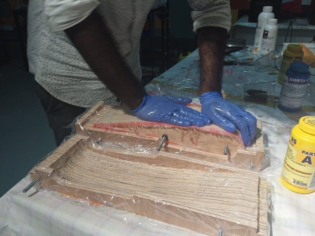
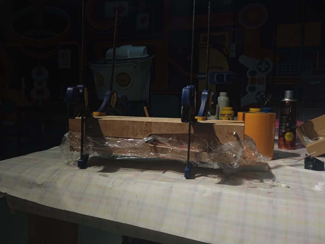
Once the core mold was wrapped in multiple layers of fiberglass sheets, I placed it between two additional molds to create a sandwich-like structure. To secure the molds together, I utilized clamps, ensuring a tight fit. Now, all that remains is to patiently wait for the required curing time, allowing the composite material to set and solidify.
The process of removing the mold and adjusting the flexibility of the resulting product involved several steps. Initially, the outer mold was effortlessly removed, ensuring a smooth start to the procedure. The plastic wrapping method proved to be effective, securely holding the mold in place during removal. However, challenges arose when dealing with the middle mold, which proved to be difficult to remove.
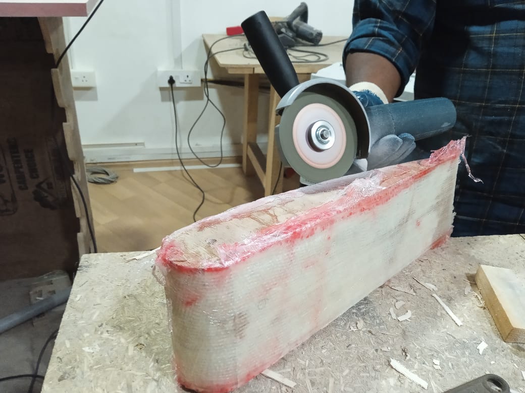
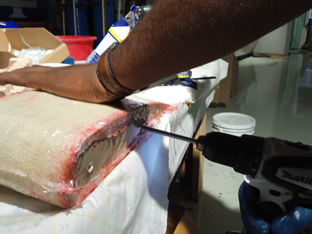
To overcome the obstacle posed by the stubborn middle mold, an angle grinder was employed to grind the edges, facilitating access to the core mold. Taking a systematic approach, the core mold was removed piece by piece by attaching a screw and using a drill to carefully extract each section. This meticulous technique allowed for the controlled dismantling of the middle mold.
After successfully removing the mold components, the flexures became accessible for adjustment. It was observed that the flex wings were in good working condition, demonstrating the desired functionality. With the flexures intact, the resulting product showed promise.
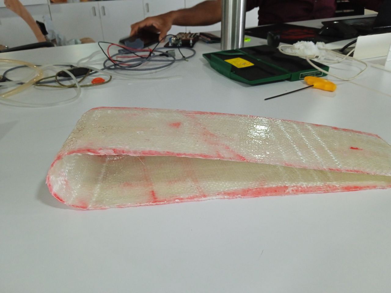
However, a notable issue surfaced concerning the overall tightness of the mold. It became apparent that the mold was not tight enough, leading to a decrease in flexibility. This finding suggests that the insufficient tightness of the mold directly impacted the final product's flexibility. Despite this setback, the overall functionality of the product remained satisfactory.
When it came to the product, the overall system was not satisfactory. The molding and casting of the composite were acceptable, but the composite exhibited unexpected flexibility in areas where it was not intended. Overall, I failed to control the flexibility of the material due to insufficient amounts of resin added. As a result, it may not function as I intended, but it did work in a different manner. As somebody once said, 'It's not much, but it's honest work.'
Additionally, I plan to incorporate a servo to actuate the wing if I find the time to do so. This addition could potentially enhance the functionality of the product and provide better control over its movements. However, given the constraints of time, it remains uncertain if I will be able to implement this feature. Nevertheless, I will make an effort to explore the possibility and assess the feasibility of integrating a servo into the system.