
12.Molding and casting
Group Assignment
For the week's start, I wanted to create a turbine blade with air cooling ducts. In order to do that, I wanted to familiarize myself with metal casting. Even though I am a mechanical engineer, I have no previous experience in casting or designing turbine blades, so I just have to wing it to create the design. Even though the technology is replaced by composite manufacturing nowadays, I want to create the design so that I could have some fun with it.
Design
For the design, I started with Fusion. I didn't do any calculations or anything. I simply created a basic design using simple calculations in my mind, aiming for it to look like a turbine blade. Now I realize that my design skills are lacking, so keeping that in mind, I created a simple design of a blade as an inset and finished my design.

I designed it in a way that would allow me to create it using a two-piece mold, and possibly a three-piece mold if I can improve my 3D design in Fusion 360.
After finishing my initial design, I realized that it was too large and would require a significant amount of machinable wax, which is in low availability for our project. Since the objective of this week is to familiarize myself with molding and milling, and considering my lost interest in scaling the design, I have decided to create a completely new design instead.
After referring to the internet, I decided to create a Mayan-style pendant. However, I realized that the geometries in the design were quite complex and would require intricate milling using different tools, which may not be feasible given the availability of resources and time constraints. As a result, I decided to simplify the design and create a pendant with a skull and Mayan-style patterns on the sides. I began working on the new design after spending some time researching and gathering inspiration.
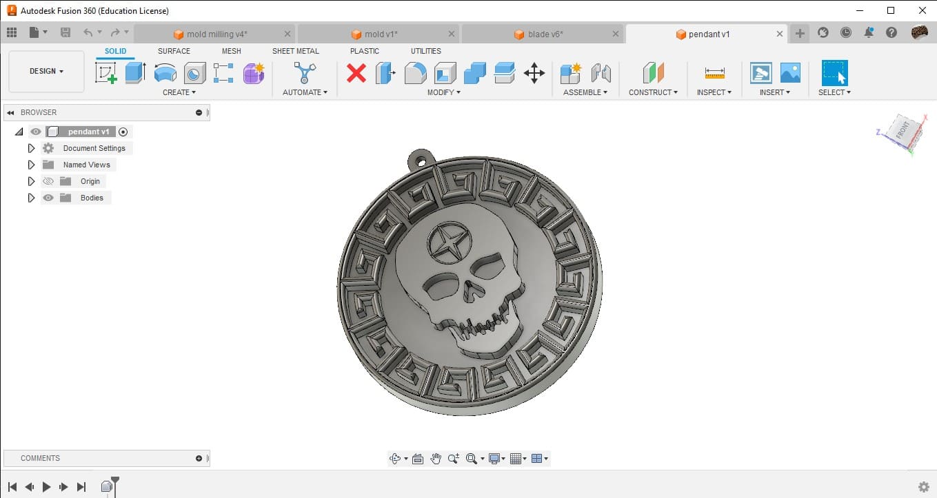
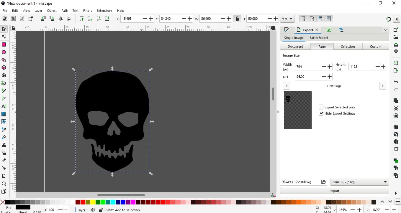
As for the design, I used the internet to download an image of a skull. I traced the bitmap using Inkscape and converted it into an SVG file. Later, I exported the file to Fusion 360, scaled it, and created a Mayan-style pattern around the body to complete the design. Once the basic design was complete, I extruded a base and created a hole for the lock. After that, the design was complete.

After completing the design, I needed to create a mold for the silicone mold. In order to do that, I created a block of machinable wax measuring 77x180x37 mm, which is the available size for us. Next, I created a pocket to hold the design and aligned it to the center.
After that, I was ready to proceed with CAM in Fusion 360.CAM
Milling is a process that uses a cutting tool to remove material from a workpiece. In the context of Fusion 360, milling involves creating toolpaths that guide a cutting tool along a predefined path to remove material from a workpiece. This process can be used to create complex shapes and features in a wide range of materials, including metals, plastics, and composites. In Fusion 360, milling is accomplished using the CAM (computer-aided manufacturing) workspace. This workspace allows users to define the cutting tool, material, and machining parameters, as well as create the toolpaths that will guide the cutting tool. The CAM workspace also allows users to simulate the machining process to ensure that the toolpaths are correct and that the final product will meet the desired specifications. Once the toolpaths have been defined and simulated, they can be exported as G-code, which is a language that controls CNC (computer numerical control) machines. The G-code can then be used to control a milling machine to create the final product. In the context of the text above, milling was used to create a mold for a silicone mold of a pendant design. The design was created in Fusion 360, and the CAM workspace was used to define the toolpaths for milling the mold out of machinable wax.
.png)
In order to access the Manufacturing workspace in Fusion 360, go to the Machining section of the dropdown menu and select Manufacturing Environment. Once in the environment, we need to set up some things. First, we need to set up the machining interface. To do that, go to Setup > New Setup. After clicking that, select the parameters required for the design, such as X, Y, and Z axes. After setting that up, we need to define the tools required for the job. To add tools to the tool library, go to Manage > Tool Library. From the local library, add the tools required for the job, or if desired, the entire inventory can be added. In my case, I added all the tools I may need to use and started my design.

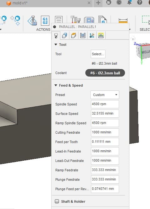
During the week, all my designs were based on detailing rather than the design constraints offered by the machine or the CAM software in Fusion 360. As a result, the two main tools I used in 3D milling were "adaptive" clearing and "pocket" clearing. For the 6 mm bit, I used adaptive clearing since most of my design consisted of flat ends. For the 3 mm and 1.5 mm bits, which were also flat-ended, I used "flat" clearing. Lastly, for finishing, I used a 2.5 mm ball-end bit, as it was the smallest ball-end bit available in my lab. In total, I used four different bits for my CAM.

After finishing the design, I just needed to click on "simulate" to see the path that the machine would follow for milling. Once I had simulated the process and reviewed the toolpaths, I was ready to export the G-code. To do this, I right-clicked on the job and selected "post process." Then, I chose the location where I wanted to save the G-code, selected the same tools, and proceeded to export the G-code.
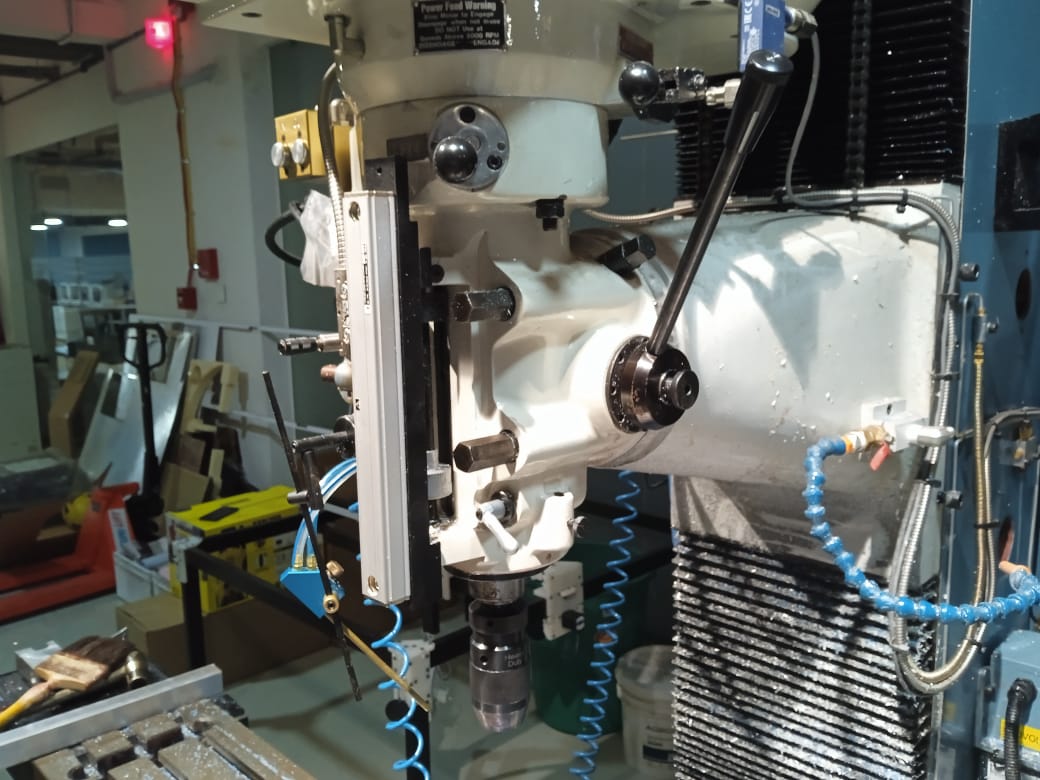
DPM RX 2- Vertical Milling Machine

The vertical milling machine is a precision tool used for shaping and fabrication by the removal of stock typically from metallic work pieces. These operations provide a flat surface or spot on a work piece, typically with a specific orientation to other work piece features, surfaces, or another piece.
Table Size: 1240 x 230 mm
Motor Type: 3 HP Continuous Spindle Motor
Axis travel: 800 x 400 x 650 mm
Spindle Taper: R8
Head Swivel: +/- 90 degrees
Quill Diameter: 33/8 inch
Maximum Quill Travel: 5 inch
Applications: Manual and CNC milling of metals
Setup
To set up the machine, first switch it on and place the workpiece on the machine vise. After fixing the material, we need to set the origin of the machine. This can be done by adding the tool offset of the machine after fixing the edge finder on the machine. Once the origin is fixed, we need to insert the program and set the tool offset of the machine. The tool offset is defined for machining with different tools. After setting all the parameters, we can run the program after checking the flute. Define the rotation of the tool accordingly.
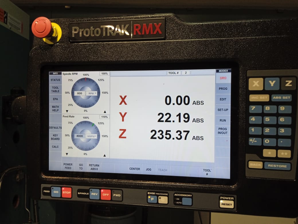
After fixing the material, turn the rotary encoders to move the Z and Y axes. Alternatively, you can use the machine interface and the edge finder to fix the X and Y coordinates, and then fix the absolute X and Y axes. Next, fix the Z axis by moving the tool downward. Once all adjustments are completed, fix the reference Z axis using the tool downward. The tool reference is added to ensure the origin is fixed during tool change.
After completing all the settings, set the machine to track and jog using the rotary encoders. If everything is working properly, run the machine on G code and observe it finishing the work. After running the G code for a tool change, define the Z offset and tool parameters for the new tool, and then run the machine again. Once the machine is set up, the process is complete.

After milling, I discovered that some of the G codes were running in mid-air. The shank we were using for the 3 mm bit was loose, which may have caused the milling depth to be incorrect. Additionally, the G codes for the 1.5 mm bit were also running in mid-air. I double-checked the simulation in Fusion and found no errors. To confirm whether the issue was with the G code or the shank, I conducted another milling test on the other side of the wax block.
While examining the milled material, I noticed that it was uneven and had some projections on the surface, even though it was not supposed to have any. This indicated that there were issues with the machining process that needed to be addressed and fixed.

In order to fix that, I looked at the depth of cut and found out that the depth was 14 mm instead of 12 mm. So, I offsetted the Z-axis by 2 mm and re-did the milling. After milling, the output was okay, and I have finished my milling.
Moulding

After milling, it's time for molding. To do that, I need to create an outer body for my mold because I destroyed that part while designing. So, more work for me. I used double-sided tape to hold the sheets to the wax brick and created a cavity. Then, I mixed the materials together and poured the material into the mold.

Silicone rubber compound called 1010 Silicone Rubber RTV (Room Temperature Vulcanizing). It is a two-component silicone rubber that is designed for mold making and prototyping applications. The compound is composed of a silicone rubber base and a curing agent, which are mixed together in a specific ratio to initiate the curing process.

Once mixed, the compound cures at room temperature, forming a flexible and durable rubber mold that can withstand high temperatures and is resistant to chemicals and weathering. This makes it suitable for use in a variety of applications, such as casting resin, concrete, and plaster, as well as in creating complex molds for architectural restoration, sculpture, and industrial prototyping.
The 1010 Silicone Rubber RTV has a high tear strength and elongation, which allows it to capture fine details and reproduce them accurately in the final casting. Additionally, it has good flow properties, enabling it to penetrate intricate and irregular shapes easily, ensuring that the final cast is free of any bubbles or voids. Overall, the 1010 Silicone Rubber RTV is a versatile and reliable silicone rubber compound that can be used to create high-quality molds for a wide range of applications.
Within 6 hours, my mold was complete. The removal of the mold was fairly easy and satisfying. After everything was complete, I was ready to do the casting. While I looked at the mold and the block of wax, my instructor Saheen told me that the wax may break. But to his and my surprise, it was not broken, and everything was alright with the mold. Due to the complexity of the mold, I had a small pocket, but now I consider it as a design.

Casting
Aditya Clear Cast Epoxy is a two-part, high-performance epoxy resin system that is designed for casting and coating applications. It is composed of a resin component and a hardener component, which are mixed together in a specific ratio to initiate the curing process. Once mixed, the compound cures to a clear, glossy, and durable finish that is resistant to UV radiation, moisture, and chemicals.
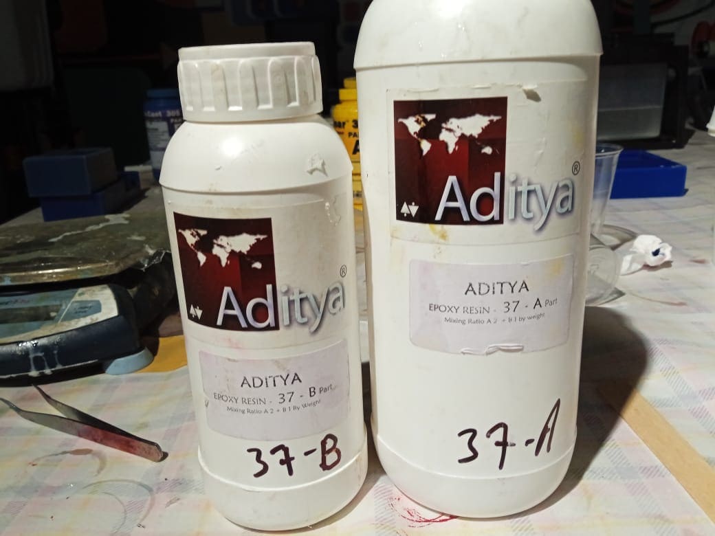
The Aditya Clear Cast Epoxy has a low viscosity, which makes it easy to work with and allows it to flow easily into intricate and complex molds. It also has a long working time of up to 45 minutes, giving users ample time to work with the material and make any necessary adjustments before it starts to cure.

the mixing ratio for Aditya Clear Cast Epoxy is typically 2 parts resin to 1 part hardener by volume. It is important to mix the two components thoroughly in the recommended ratio to ensure proper curing and optimal performance. It is also important to note that temperature and humidity can affect the curing time of the epoxy.
Now it's my time to cast, and I selected the epoxy resin. While I looked at the pigments, I selected two pigments: black as the background and golden yellow as texture. Even though it is not the correct method, I used a syringe to add the resin to the detailed parts and waited for 5 hours to let the part set for a while. After that, I mixed some black pigment with the resin and poured it over the rest and completed the cast. Now I await the result.
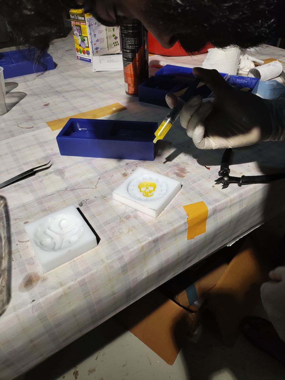
After some time, the cast was finished and it came out good, not great. I had expected it to have a more vibrant, inspiring depth with a golden-yellow hue, but it didn't. However, it was a nice learning experience for me, and I enjoyed it.

---HERO-----SHOT---
