11.Input devices
Group AssignmentAt the beginning of the week, I began by assessing the available input devices. After careful consideration, I opted to use rotary encoders and a joystick module, despite having no prior experience with either of them. My main objective was to thoroughly research and familiarize myself with these input devices.
The output devices available in the lab are.
Hall effect sensor
Phototransistor
Thermistor
Radar motion sensor
PDM microphone
Rotary encoder
Ultrasonic sensor
Accelerometer
Mic
Piezoelectric transducer
Joystick
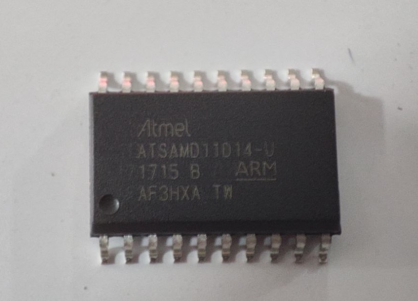
SAMD11 D14A-U DEV Board
For the week, I began by going into the inventory and selecting the chip labeled as 'SAMD11 D14A-U'. However, the problem arose as nobody in the lab had previously used this chip, and there was no information available about its pinout. Additionally, I was using the Arduino IDE as a compiler, but the SAMD core library didn't have a bootloader for the 'AU' variant. The library only had options for 'AM' with 24 pins and 'AS' with 20 pins, with 'AS' being closer to 'AU' which had 20 pins. Upon checking the datasheet, I realized that the ports for the device ID were different for this chip. As a result, we had no idea if it could be compiled.
To test whether we could use the chip, the lab instructors assigned me the task of creating a development board using the chip. The purpose of the development board was to test the functionality of the chip.
With that in mind, I began using Fusion to design the circuit. I added a power LED and an internal LED to check the circuit, along with all the other necessary pins connected to female SMD connectors. I also included pins for the SMD programmer and for connecting a micro USB. Once the design was complete, I exported the file and was ready to proceed with milling.
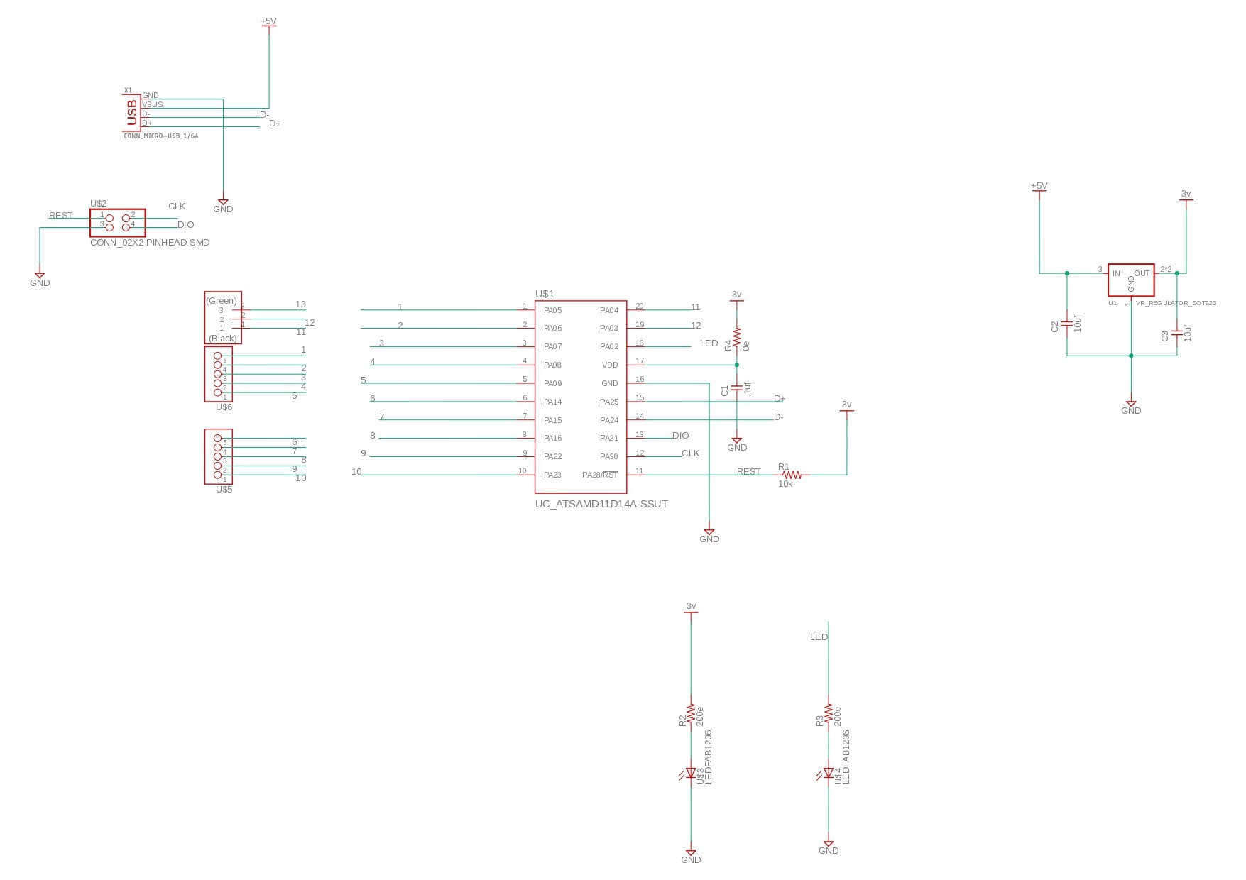
I recently found out that I could create HTML components from Fusion 360, even though they may not look pleasing. However, it is faster and easier to do so. So, no hard feelings if the component list looks weird. The components used were:
| Part | Value | Device | Package | Description | |
| .1uf | CAP_UNPOLARIZEDFAB | C1206FAB | |||
| 10uf | CAP_UNPOLARIZEDFAB | C1206FAB | |||
| 10uf | CAP_UNPOLARIZEDFAB | C1206FAB | |||
| 10k | R1206FAB | R1206FAB | Resistor (US Symbol) | ||
| 200e | R1206FAB | R1206FAB | Resistor (US Symbol) | ||
| 200e | R1206FAB | R1206FAB | Resistor (US Symbol) | ||
| 0e | R1206FAB | R1206FAB | Resistor (US Symbol) | ||
| UC_ATSAMD11D14A-SSUT | UC_ATSAMD11D14A-SSUT | SOIC127P1030X265-20N | |||
| CONN_02X2-PINHEAD-SMD | CONN_02X2-PINHEAD-SMD | 2X02SMD | |||
| LEDFAB1206 | LEDFAB1206 | LED1206FAB | LED | ||
| LEDFAB1206 | LEDFAB1206 | LED1206FAB | LED | ||
| TERM-1X05 | TERM-1X05 | 1X05_SMD-FEMALE | 3.5mm terminal block, 3 positions ED555-3DS as found in the fablab inventory. | ||
| TERM-1X05 | TERM-1X05 | 1X05_SMD-FEMALE | 3.5mm terminal block, 3 positions ED555-3DS as found in the fablab inventory. | ||
| CONN_03-SMD-HEADER_2SIDE | CONN_03-SMD-HEADER_2SIDE | 1X03SMD(2_ROW) | |||
| VR_REGULATOR_SOT223 | VR_REGULATOR_SOT223 | SOT223 | |||
| CONN_MICRO-USB_1/64 | CONN_MICRO-USB_1/64 | DX4R005HJ5_64 | SMD micro USB connector as found in the fablab inventory. |
Milling was relatively straightforward, but the milling bit we utilized was antiquated and had limited resolution, resulting in unsatisfactory output. The tracks exhibited inconsistent sizes, with some even missing or being smaller than expected, displaying non-uniform variations.
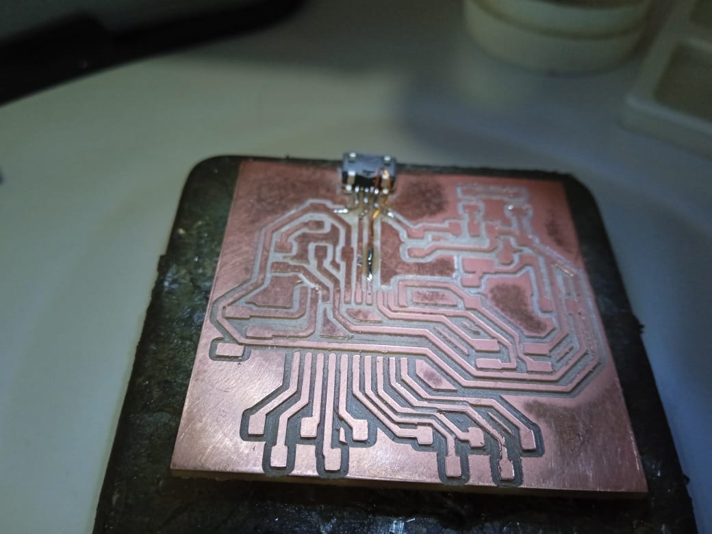
After milling, I realized that I had lost one of the pads for the micro USB connector, which meant I had to use jumper wires to establish the connection. Unfortunately, during this process, I ended up losing two more micro USB connectors.

After soldering, I was ready to program the chip and had my fingers crossed. Fortunately, I didn't encounter any issues while burning the bootloader. I used the 'SAMD11 D14' library as the bootloader and initially thought I had succeeded. However, the instructors cautioned me that it was too soon to celebrate and suggested running a basic program, like 'Blink', on the board. To my relief, it worked! We discovered that the same bootloader could be used for both the 'AS' and 'AU' variants.
Joystick and Rotary encoder Board
After confirming that everything was working fine, I was instructed to create a new board for the intended purpose. I was also told to reuse the components that I had used in the development board. With that in mind, I went back to designing the new board.

While designing, I referred to the internet to obtain the basic connections for the joystick and rotary encoder. During my research, I discovered that I would need 2 analog pins for the X and Y axes of the joystick, as well as 1 digital pin for the switch on the joystick.

Joystick
A joystick is a type of input device commonly used in electronic systems, such as gaming consoles, remote controls, and industrial control panels, to control the movement or direction of a cursor, object, or other elements on a screen or display. It typically consists of a handle or lever that can be moved in different directions (up, down, left, right, etc.) and may also have additional buttons or switches for additional functions.
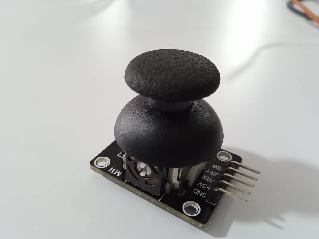
A joystick usually has one or more axes of movement, which can be either analog or digital. Analog joysticks provide smooth and continuous movement along the axes, allowing for precise control, while digital joysticks provide discrete movement along the axes, usually in predefined steps or increments. Joysticks can also have buttons or switches that can be pressed or toggled to perform additional actions or functions.
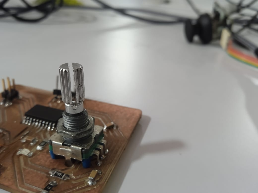
Rotary encoder
A rotary encoder is an electro-mechanical device used to measure the rotational position or movement of an object. It typically consists of a rotating disk or wheel with patterns of slots or markings and a sensor that detects the changes in the patterns as the disk rotates. These changes are then converted into electrical signals that can be processed by a microcontroller or other electronic device to determine the position or movement of the object.
There are two main types of rotary encoders: incremental and absolute. Incremental rotary encoders provide information about the change in position or movement relative to a reference point, usually in the form of pulses or quadrature signals. Absolute rotary encoders, on the other hand, provide a unique digital or analog output for each position or movement, allowing for direct and precise measurement of the absolute position.

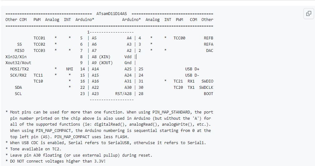
I obtained the pin mapping for the SAMD11D14AS, and the pin mapping for AS and AU chips is identical. I was able to utilize the pin mapping of AS to design my AU chip, which proved incredibly helpful as it provided pin-outs for analog pins, digital pins, interrupt pins, serial communication pins, and I2C pins, all of which were identical.
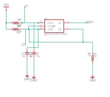
While designing, I did not have a library for the rotary encoder in Fusion 360, so I used SnapEDA to upload the files. I was also informed that rotary encoders have a minimum circuit requirement, so I referred to the datasheet to gain an understanding of the rotary encoder. According to the datasheet, it specified a 10k resistance for 5V input voltage. However, since I was using a 3V input voltage, I decided to use a 5k resistance instead.
After the designs were complete, what I needed to do was to remove all the components I took from the dev board and add them to the new board. I used a hot air gun to desolder the components from the board. I reused all the necessary components except for the micro USB. Well, I had no confidence in reusing the micro USB.

The components used in this board are.
| Part | Value | Device | Package | Description | |
| .1uf | CAP_UNPOLARIZEDFAB | C1206FAB | |||
| 10uf | CAP_UNPOLARIZEDFAB | C1206FAB | |||
| 10uf | CAP_UNPOLARIZEDFAB | C1206FAB | |||
| 1uf | CAP_UNPOLARIZEDFAB | C1206FAB | |||
| 1uf | CAP_UNPOLARIZEDFAB | C1206FAB | |||
| 10k | R1206FAB | R1206FAB | Resistor (US Symbol) | ||
| 100e | R1206FAB | R1206FAB | Resistor (US Symbol) | ||
| 100e | R1206FAB | R1206FAB | Resistor (US Symbol) | ||
| 5k | R1206FAB | R1206FAB | Resistor (US Symbol) | ||
| 5k | R1206FAB | R1206FAB | Resistor (US Symbol) | ||
| 0e | R1206FAB | R1206FAB | Resistor (US Symbol) | ||
| 5k | R1206FAB | R1206FAB | Resistor (US Symbol) | ||
| UC_ATSAMD11D14A-SSUT | UC_ATSAMD11D14A-SSUT | SOIC127P1030X265-20N | |||
| CONN_02X2-PINHEAD-SMD | CONN_02X2-PINHEAD-SMD | 2X02SMD | |||
| LEDFAB1206 | LEDFAB1206 | LED1206FAB | LED | ||
| LEDFAB1206 | LEDFAB1206 | LED1206FAB | LED | ||
| 1X05_SMD | 1X05_SMD | 1X05_SMD | |||
| VR_REGULATOR_SOT223 | VR_REGULATOR_SOT223 | SOT223 | |||
| PEC12R-4025F-S0024 | PEC12R-4025F-S0024 | ENC_PEC12R-4025F-S0024 | Encoder 12mm 0detents 20mm Shft Push Momentry Sw 24 Pulse Check availability | ||
| X1 | CONN_MICRO-USB_1/64 | CONN_MICRO-USB_1/64 | DX4R005HJ5_64 | SMD micro USB connector as found in the fablab inventory. |
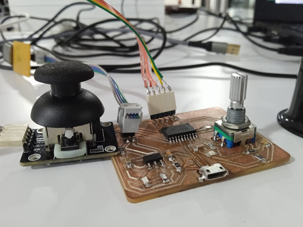
After soldering my PCB was complete, and I also lost an LED because while checking with the multimeter, it wasn't working, so I had to replace the LED. After soldering all the components and connecting to power, I found out that the previous program I uploaded was still running on the microchip. The way I figured it out was that I had used pin 2 for the internal LED, and while connecting the internal LED was blinking, and I knew I had my program running. I had no reason to burn the bootloader to the microchip again.
I made a mistake while designing the board. I designed the board with the intention of connecting the joystick using a female jumper connection, but I forgot about the existence of a sideways 1x5 female SMD connector. As a result, if I connect the joystick directly to the board, it will be upside down. This was a mistake on my part for not clearly considering all the aspects. As a workaround, I had to connect the joystick using jumpers instead of direct connection. With everything in place, I was ready to run the program for the joystick and rotary encoder.
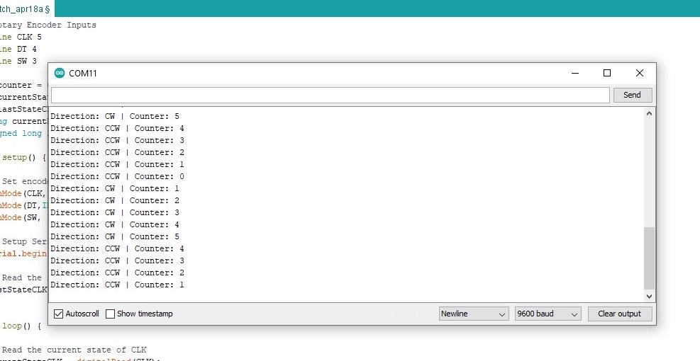
After taking care of everything, I was ready to start programming. For the rotary encoder, I wrote a simple program to serial print the rotation values as integers and display a message when the button is pressed. The code worked perfectly fine, and the serial monitor displayed the values of each rotation and button press.
The code I used was.
// Rotary Encoder Inputs
#define CLK 5
#define DT 4
#define SW 3
int counter = 0;
int currentStateCLK;
int lastStateCLK;
String currentDir ="";
unsigned long lastButtonPress = 0;
void setup() {
// Set encoder pins as inputs
pinMode(CLK,INPUT);
pinMode(DT,INPUT);
pinMode(SW, INPUT_PULLUP);
// Setup Serial Monitor
Serial.begin(9600);
// Read the initial state of CLK
lastStateCLK = digitalRead(CLK);
}
void loop() {
// Read the current state of CLK
currentStateCLK = digitalRead(CLK);
// If last and current state of CLK are different, then pulse occurred
// React to only 1 state change to avoid double count
if (currentStateCLK != lastStateCLK && currentStateCLK == 1){
// If the DT state is different than the CLK state then
// the encoder is rotating CCW so decrement
if (digitalRead(DT) != currentStateCLK) {
counter --;
currentDir ="CCW";
} else {
// Encoder is rotating CW so increment
counter ++;
currentDir ="CW";
}
Serial.print("Direction: ");
Serial.print(currentDir);
Serial.print(" | Counter: ");
Serial.println(counter);
}
// Remember last CLK state
lastStateCLK = currentStateCLK;
// Read the button state
int btnState = digitalRead(SW);
//If we detect LOW signal, button is pressed
if (btnState == LOW) {
//if 50ms have passed since last LOW pulse, it means that the
//button has been pressed, released and pressed again
if (millis() - lastButtonPress > 50) {
Serial.println("Button pressed!");
}
// Remember last button press event
lastButtonPress = millis();
}
// Put in a slight delay to help debounce the reading
delay(1);
}
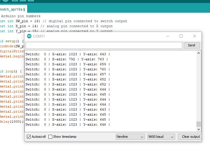
Regarding the joystick, I made modifications to the serial read program to capture the X and Y coordinates of the joystick. The issue was that the joystick had no negative values and started from 754 for both up and down directions. I needed to reprogram the chip to obtain more accurate values. Additionally, I wanted to register the joystick as a keyboard, which required additional time for implementation.
The code used was.
// Arduino pin numbers
const int SW_pin = 16; // digital pin connected to switch output
const int X_pin = 14; // analog pin connected to X output
const int Y_pin = 15; // analog pin connected to Y output
void setup() {
pinMode(SW_pin, INPUT);
digitalWrite(SW_pin, HIGH);
Serial.begin(9600);
}
void loop() {
Serial.print("Switch: ");
Serial.print(digitalRead(SW_pin));
Serial.print(" | ");
Serial.print("X-axis: ");
Serial.print(analogRead(X_pin));
Serial.print(" | ");
Serial.print("Y-axis: ");
Serial.print(analogRead(Y_pin));
Serial.println(" | ");
delay(1000);
}