
10.Mechanical design & machine design
Group Assignment
The week was full of chaos. We were finding order within the chaos we created. The chaos we created was very bad; I even forgot the things I did. So, documentation is my method of remembering what I did during the week. I had no official role in what I was supposed to do, but at last, I was tasked with designs. Despite the chaos, the work was fairly enjoyable and easy. Everyone was concentrating on their strong suits and supporting each other. I have to say, I was doing what I pleased and having fun.
Designing with fusion
Collaborative design in Fusion 360
Collaborative design in Fusion 360 is a process in which multiple designers or team members work together on a single design project in real-time. It allows multiple individuals to simultaneously contribute to a design, making it more efficient, productive, and often results in better designs than would be possible with just one person working on their own.
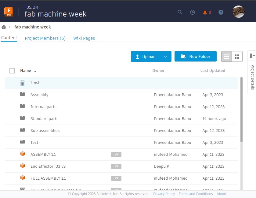
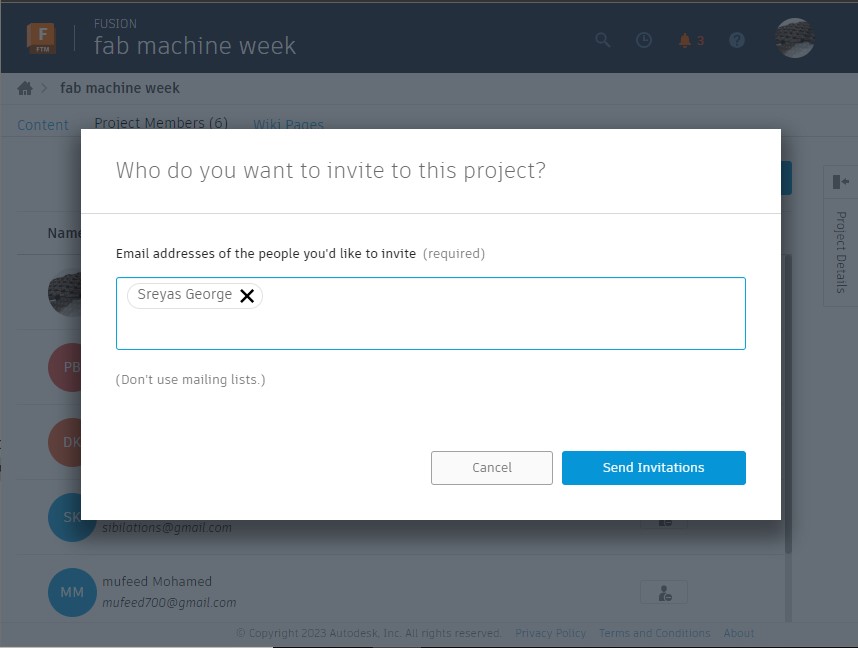
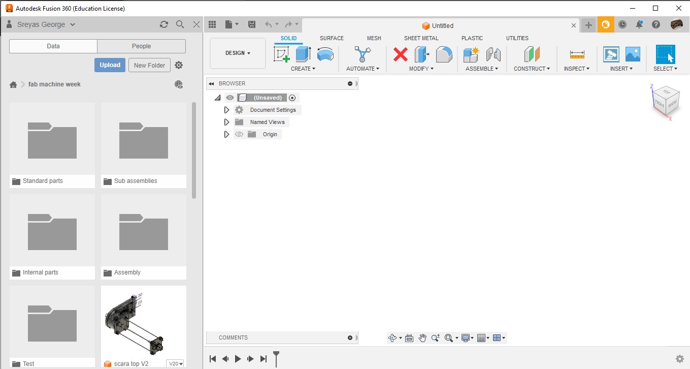
To create a collaborative design environment, I created a folder called 'Fab Machine Week' and invited all the members of the group. You can do this by creating a folder and adding members in the Fusion 360 environment or your Autodesk account. From there, we started the collaborative design process. First, we created different folders for assemblies, sub-assemblies, and standard parts, and then we began designing individually.
Base
During the week, the first task I received was to design the base, the rotational movements of the base, and the z-axis in our collaborative environment. Praveen had already added the standard parts for the design, and Deepu from my group helped me in making a standard design for the z-axis. I added the materials from Master Carr in Fusion 360 and cross-checked them with the parts available in the lab.


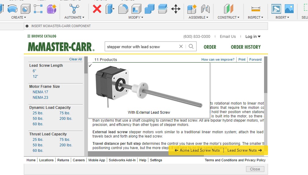
McMaster-Carr is a well-known supplier of industrial parts and components, and their website has a vast catalog of products that are used in various industries. If you are designing a project and need to incorporate a specific component from McMaster-Carr, you can easily import its design into Fusion 360. To do so, you can access the McMaster-Carr component library directly from within Fusion 360 by selecting "Insert McMaster-Carr Component" from the "Insert" menu. This will allow you to browse through the different categories of components available from McMaster-Carr. Once you find the desired component, you can select it and download the STEP file, which is compatible with Fusion 360. After importing the design, you can modify it to suit your specific needs using Fusion 360's wide range of tools. You can scale the component, modify its shape, or make other changes to ensure it fits seamlessly into your design.
For the week, we referred to some designs from the internet, but we needed to make them according to the materials we had available. With that in mind, I started designing, beginning with the top and the stepper motor for the z-axis. I used four linear rods of 8mm for support and an 8mm screw connected with the stepper for z-axis movement.

When it came to the base, I had no idea what I was supposed to do, but my instructors and others guided me. Deepu designed most of the assembly parts, and the position of the belt and motor was designed by me with the help of my instructor, Jogin Francis.
When it came to the design, I was instructed to make it as small as possible since we were using 3D printing as the main manufacturing method. It had to fit the bed size of the 3D printer we were using. So, I designed it as compact as possible. We took some pulleys from the designs we were copying and added pulleys from the available inventory. For the bigger pulleys that were not available at the lab, we just 3D printed them.
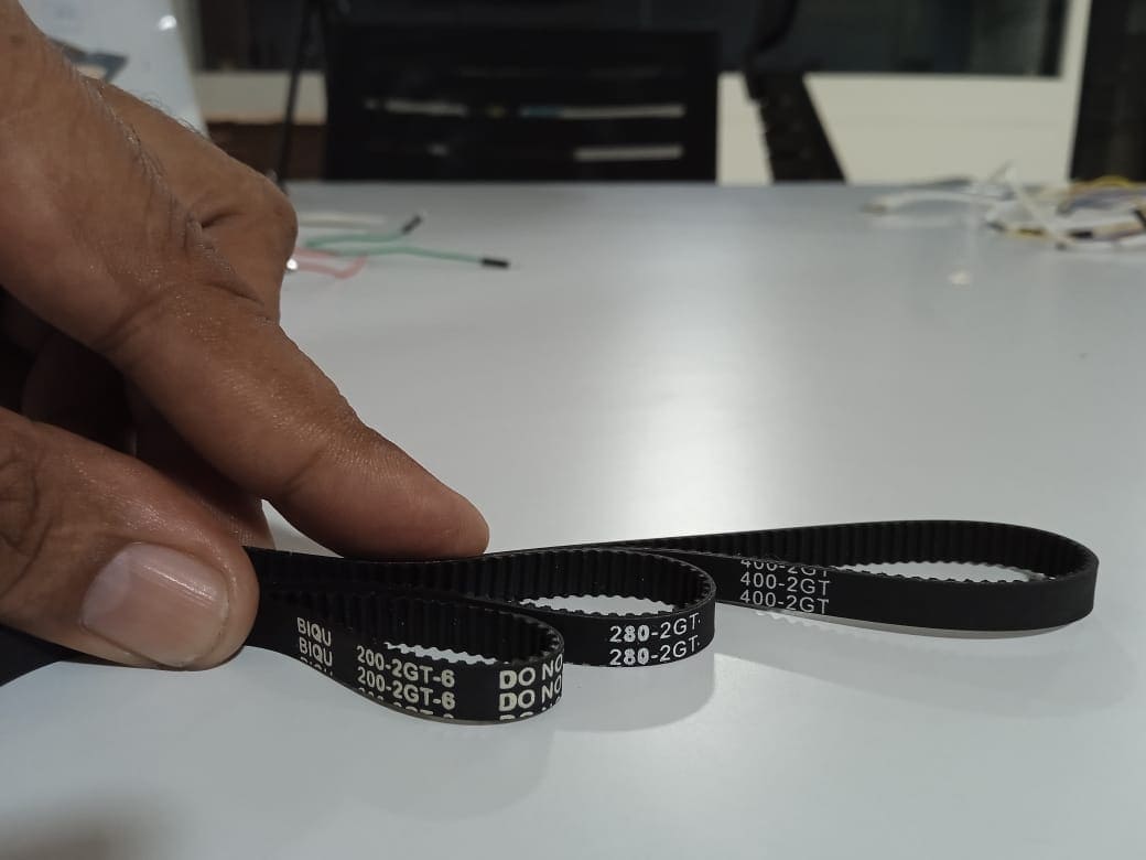
To start with the base, I began with a 3D image of the position of the pulleys. I already knew the length of the available timing belts, which were GT2 timing belts in lengths of 200, 280, and 400. The 400 belt was too big, and the 200 belt was too small. So, I decided to go with the 280 timing belt and started creating a 2D design for reference.
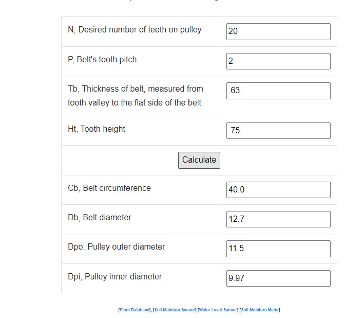
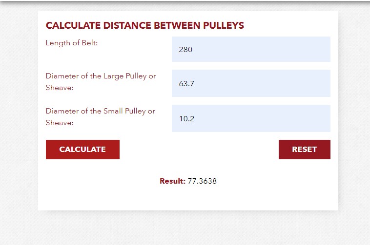
The pulleys used in the base were the first with a 110 to 22 gear reduction, the second with an 80 to 16 gear reduction to the motor. The next thing I needed to know in the design was the pulleys' outer diameter and the distance between the pulleys . Luckily, I found two websites that could do the math for me. I found out the outer diameter of the pulleys on one website and the distance between the pulleys on the other website. With that, I was ready to make the 2D reference image of the pulleys and motor. In the first website, I put in the GT2 timing belt parameters and found the diameter of the pulleys. Everything was fairly easy.
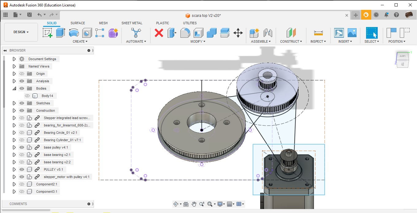
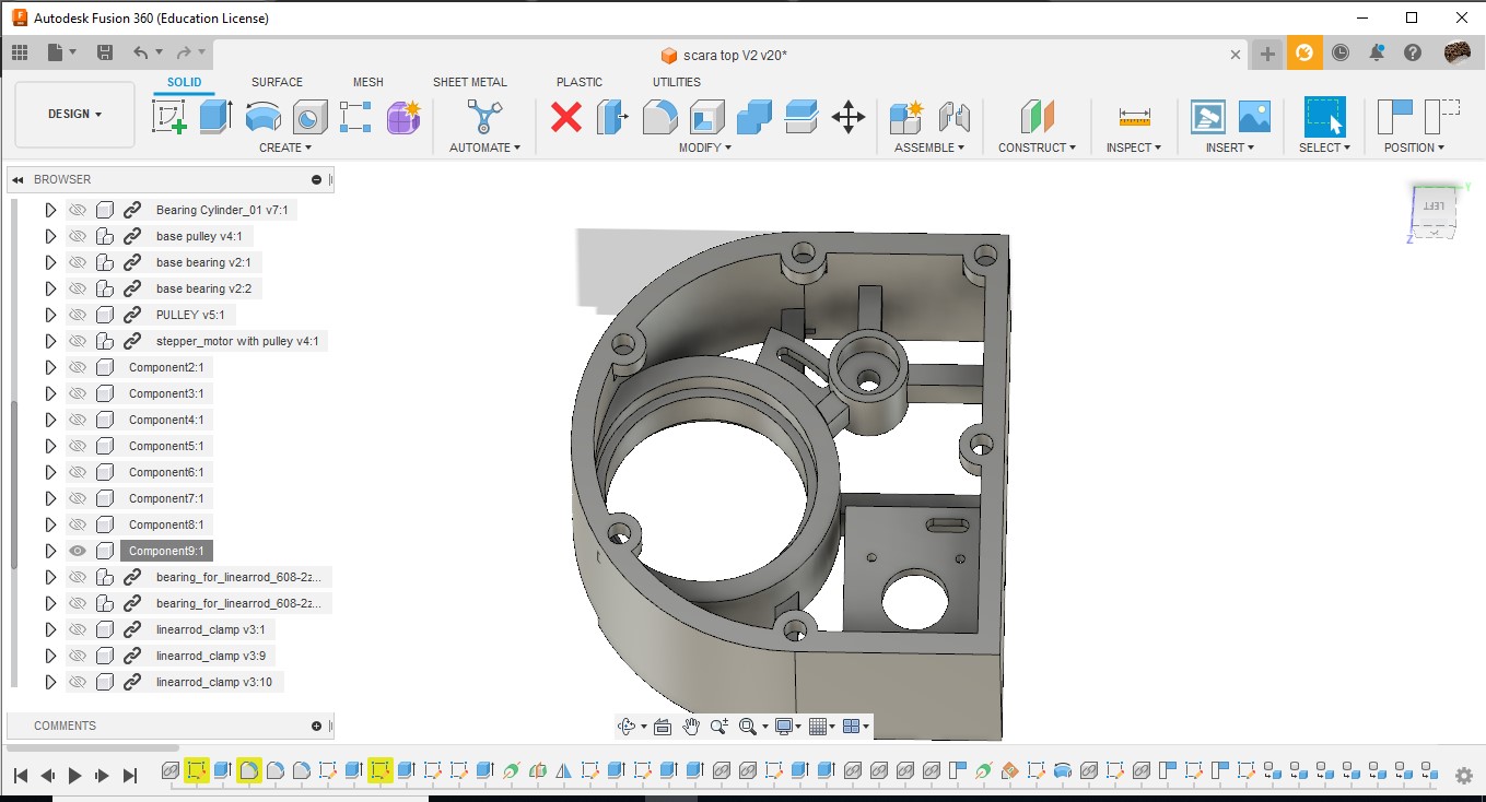
While designing the base, I used the base image to align the pulleys and motors in position and started my designs with the projection of the McMaster-Carr components. I used 6812-RS bearings for the main body movement and small 608-ZZ bearings for the small intermediate pulley movement. I had a certain suspicion that the belt would be loose, so I added notches for the belt tensioner just in case if the belt is loose. After creating a base based on the parts and adding the holes and notches for the cover and base's nuts and bolts, we were ready to print.
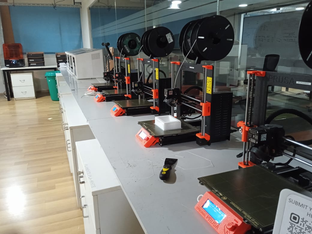
The printing took about 12 hours to complete using Prusa Mach3, with a print resolution of 0.3mm and an infill density of 20%. The base was the largest print in the entire assembly and was also the first one to be printed.
By the time the base was finished printing, the other parts were finished too. We used FDM 2D printing and printed using PLA. Others handled it very well, and we were ready to assemble the base. At the lab, there were 10 printers available in total, and we fully utilized the facility in 3D printing and printed the parts in time.
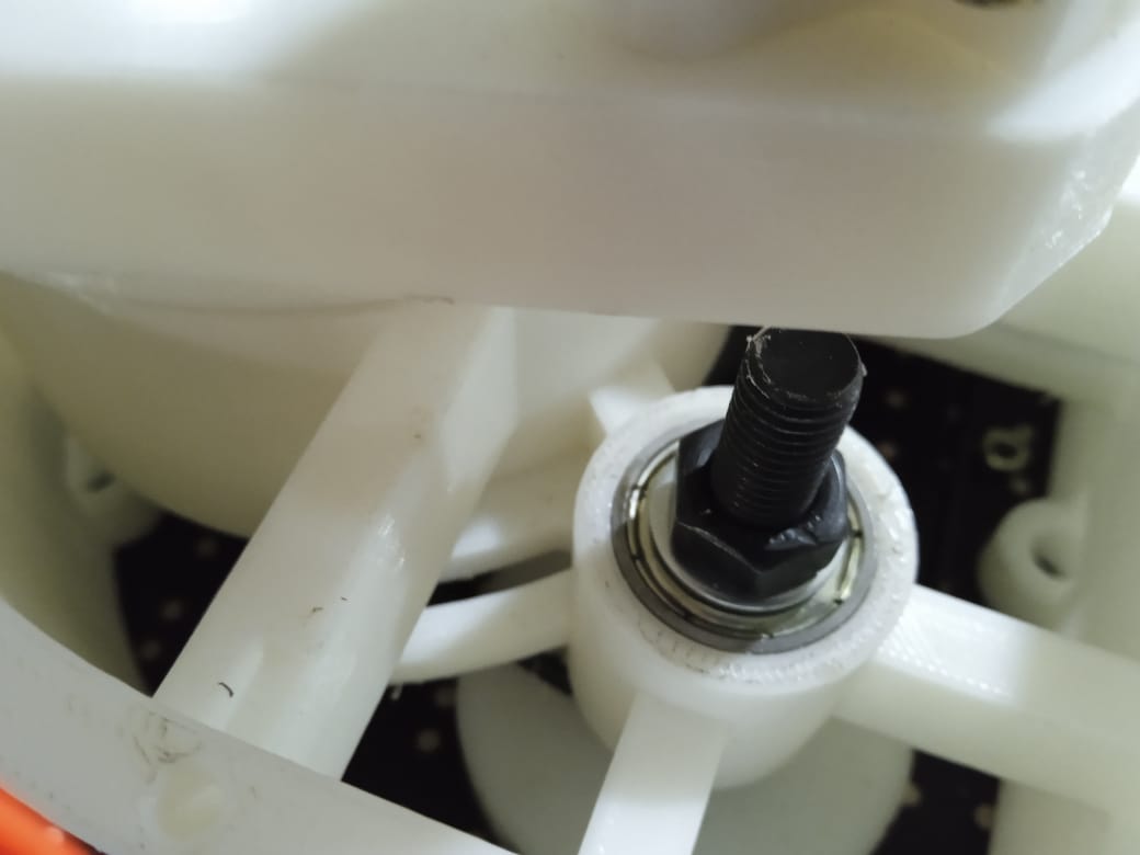
While assembling, I realized that I am a bad designer. Although I designed everything perfectly, including holes for the base and cover for the robot, I made a mistake in a small part. There were two types of bearings in the design: the bigger one, 6812-rs, and the smaller one, 608-zz, which rotates the interconnecting pulley. In the smaller pulley, I didn't give any clearance for the inner part of the bearing to rotate, even though I gave clearance for the bigger one. We only recognized this mistake after putting the bearings inside. After some effort, we removed the bearings and made the holes bigger with a drilling machine, and then it was working perfectly. Others didn't say anything and just replied with a smile.

I never got any approval from the instructors to print a bigger design, and I acted on my own in that matter. Jogin said he would kill me if there was any design failure, but he doesn't know about this mistake until now. If he reads my document thoroughly, he will know.
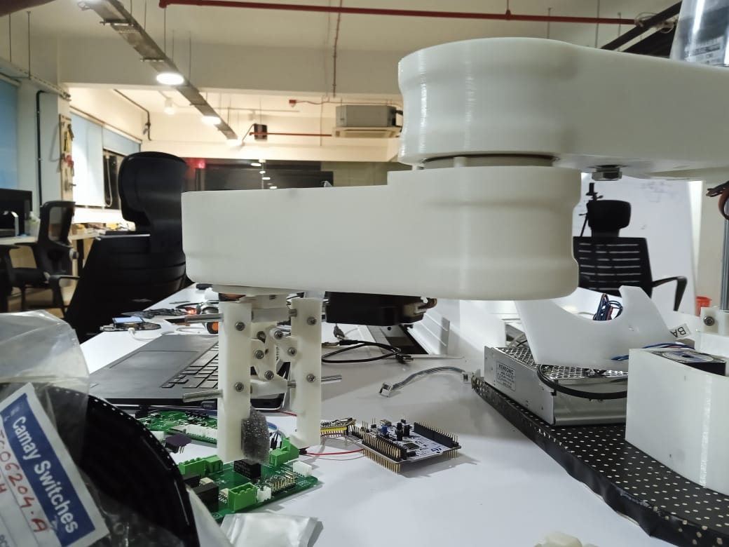
Even though I added notches for the belt tensioners, we never used them because the belts were a perfect fit and fairly tight on the pulleys. As a result, the base was completed and assembled without any further problems, and everyone was fairly satisfied.

Despite the errors, everything was working in the end, and everyone was happy with the assembly and design
Download Design Files
Second Arm
The next task that was handed to me was designing the second arm. I was fairly experienced with the designing process because I had done the design of the base, and this was an opportunity to refine my designing skills. In the designing process, Deepu had already designed the end effector, while Mufeed had done the first arm. I was present while he was designing the first arm, and the design was available to me, so I had all the resources I needed to complete the design.
First, I started with the base image of the pulleys. I decided to go with a pulley of 100 teeth and a belt length of 400, and I designed accordingly. I extracted the connector component from the second arm and end effector component from Deepu's design and designed accordingly.
I used the same websites to find the pulley diameter and distance between pulleys to create the base 2D image, and started my 3D design. I used 6806-rs bearings for the rotation of the end effector. Pulleys with 100 and 16 teeth were used in creating the design, and after I created the 3D file according to the 2D image, it was satisfactory. It had a size of 200 mm which was possible to print in the Prusa, and I was happy with it.
After referring with the group, Sibin pointed out that the connection holes to the 2nd arm and the motor were aligned vertically, which could cause problems during the assembly process. So, I modified the design by changing the pulley to 280 teeth and repositioning the motor at the center instead of the edge. Everyone agreed with the changes, and we were ready to print the updated design.

During the design, I avoided the notches for the belt tensioners because it was useless in the base and the second arm. While I am writing this, the words of my friend come to mind:
"The risk I took was calculated, but man am I bad at math."
Yes, I am bad at math and messed up again. The belt was loose and had to be fixed. Luckily, we had two pulleys in the lab to connect to the motor - a 16 teeth and a 20 teeth pulley. So, I put on the 20 teeth pulley and the belt was tight, and the problem was fixed. But I will remember this.

When it comes to functionality, I have a clear idea of what I have to do in order to make it work, and I have all the materials and vernier caliper at my disposal. But when it comes to aesthetics, I am no good. So, further modifications were done by Mufeed to my designs so it would look more pleasing. And I am glad.
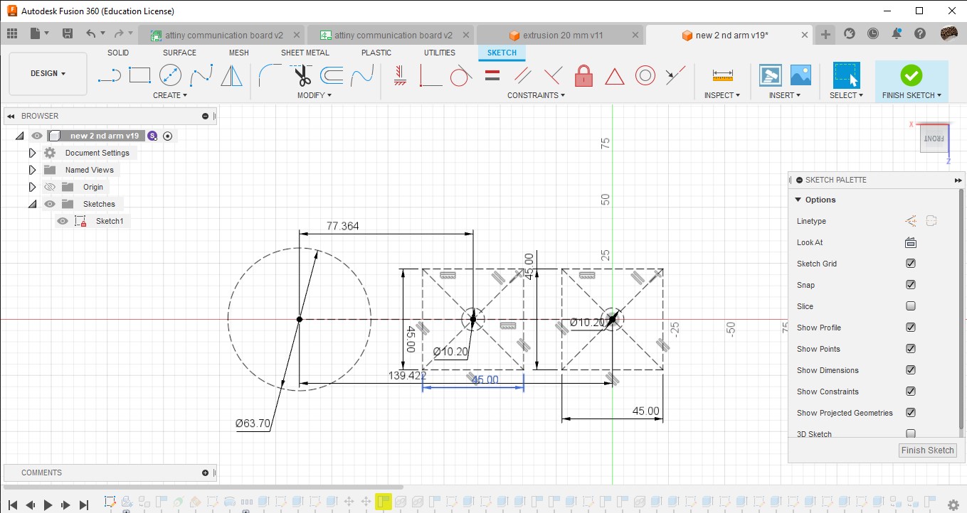
Rail
After designing all that, I was free, and when Jogin came to us on the second last day, he proposed an idea. We had a CNC shield for 5 motors, and we were only using 4. So, he proposed an idea to utilize the fifth driver. The idea goes like this: we have a rail made of aluminum extrusions in the lab, which was built for another project. The idea is to utilize the rail to add linear movement to the robot.
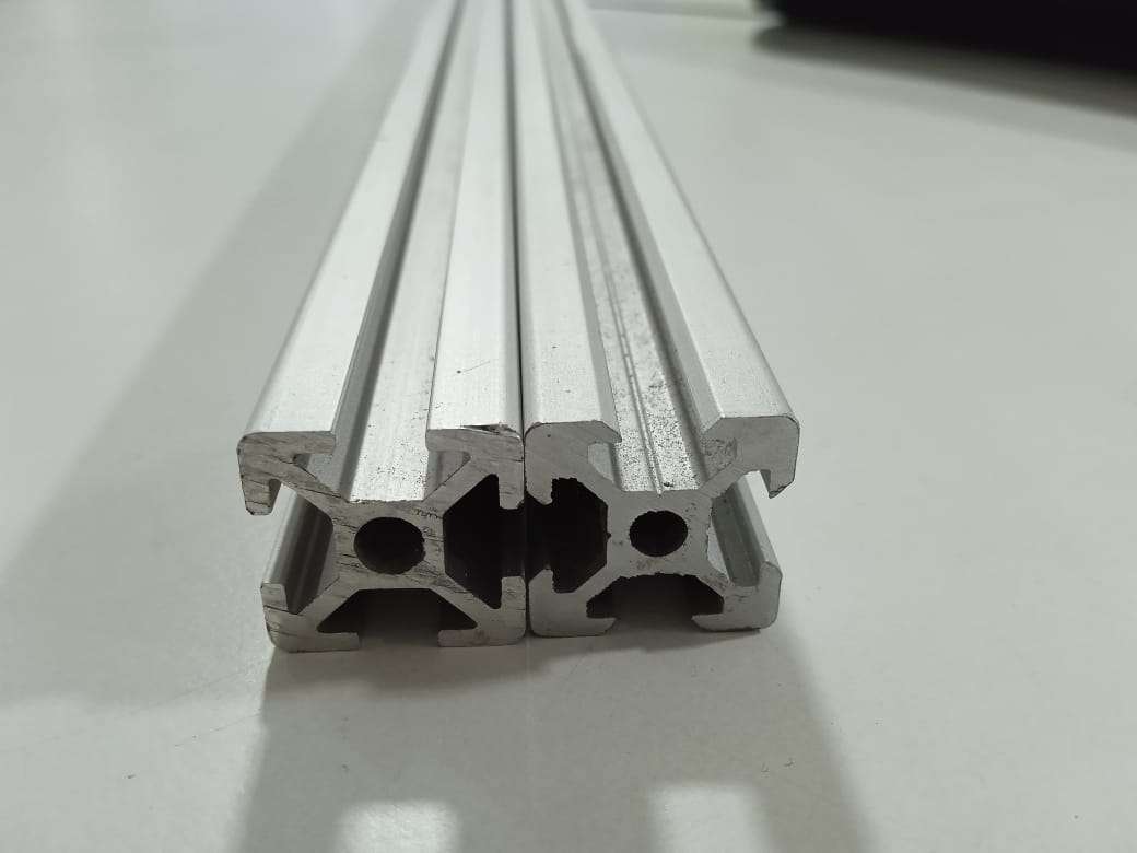
We had the rail made in the lab, and we had the design of a beautiful angle-meshed gantry designed by Jake in the lab. But the problem was, it was designed for a normal extrusion. However, the gantry we had had an extrusion of a V-notch with an angle of 90 degrees. The gantry was still moving but had some wobbling. So, I decided to make a gantry for a V-notched extrusion and started my design.

I designed it for 628zz bearings and started a 2D image of how it's going to be. The fab lab intern Ajith Sir had already started the design, so I copied his aluminum extrusion as a component and started my design.

The design was basically creating and assembling different pieces using Silhouette Split in Fusion 360 and combine tools. The project was basically a jigsaw puzzle, and at last, I extracted the STL and 3D printed it.
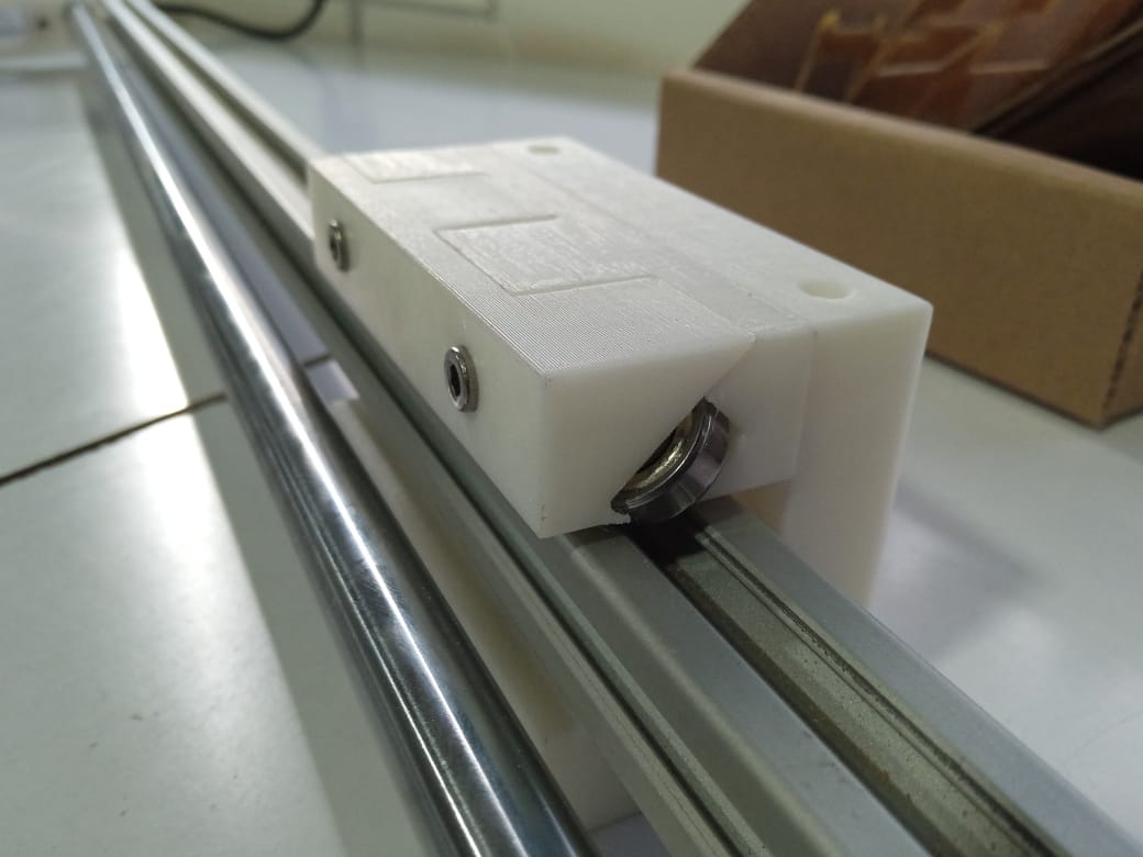
As for the work, I have to say I am not satisfied with the results. My design was more bulky and hard to assemble. I had to use some force to assemble the pieces together because of the complexity of the design. I have to say the design worked, but I didn't get the smooth movement I got from Jake's gantry in my design. But it still worked despite my first try, so I have no idea what to feel.
Because of the time limitations, it never saw the light and didn't make it to Neil's presentation. Let's see it as an extension of the project if ever we go into that again.