Output devices
WEEK - 9
Objectives
CONTENTS
Group assignment→ link here
- characterize the design rules for your in-house PCB production process
Individual
- make an in-circuit programmer that includes a microcontroller:
- mill and stuff the PCB
- test it to verify that it works
Designing a new board
Last week I made a developer board using Attiny and for this week I am using the SAMD21 processor
The Programmer
- at first, we needed to make a programmer using SAMD21 for programming the board that I am going to make
 https://gitlab.fabcloud.org/pub/programmers
- I referred this documentation for creating the programmer, all the details and files are included in that
- downloaded the Gerber file and milled the PCB using that
We were fortunate enough to have the assistance of Saheen, one of our academy seniors, who had a samd11 programmer with him to help us with our project.
we used his programmer to program ours
Designing a board with SAMD21
functions to be added to this board
My idea is to create a dev board that can be used to do the following functions
- To control a stepper motor, need to add a stepper motor controller
- An OLED display for showing various data, to show the direction and some parameters, need to add an I2C connector for using an OLED display
These are the components that were given to me, the objective was to control these.
with these points in mind, I started designing the PCB in Fusion 360
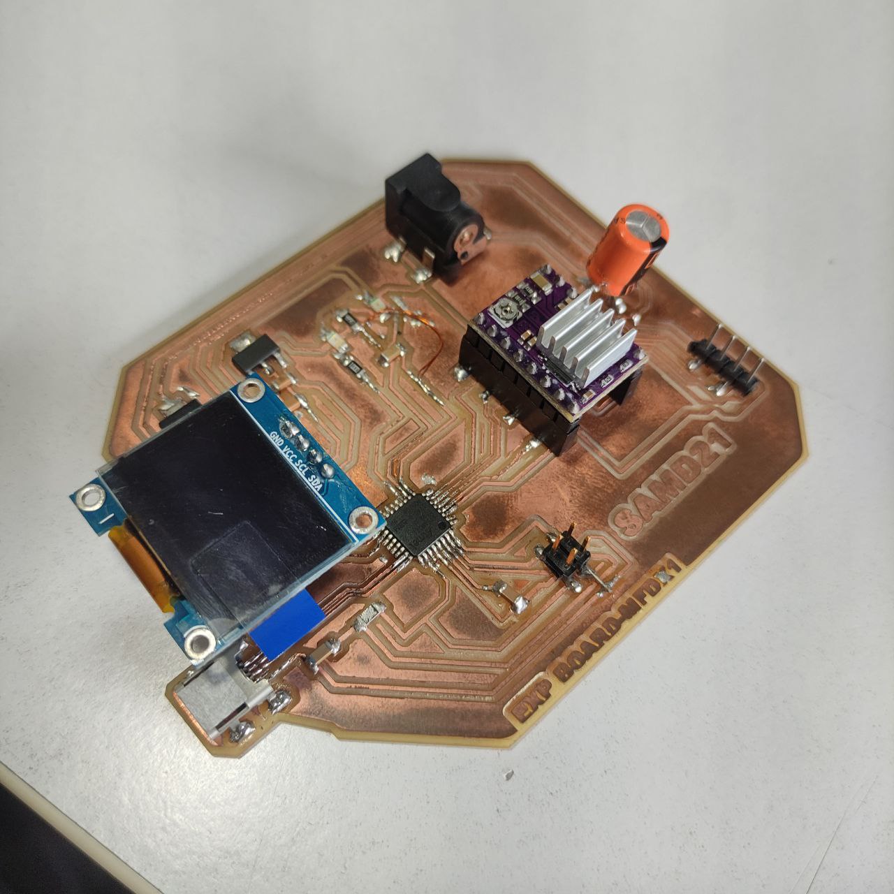
The design of my SAMD21 dev board
For the datasheet of SAMD21E- click here
- the schematic diagram of the board with all the components
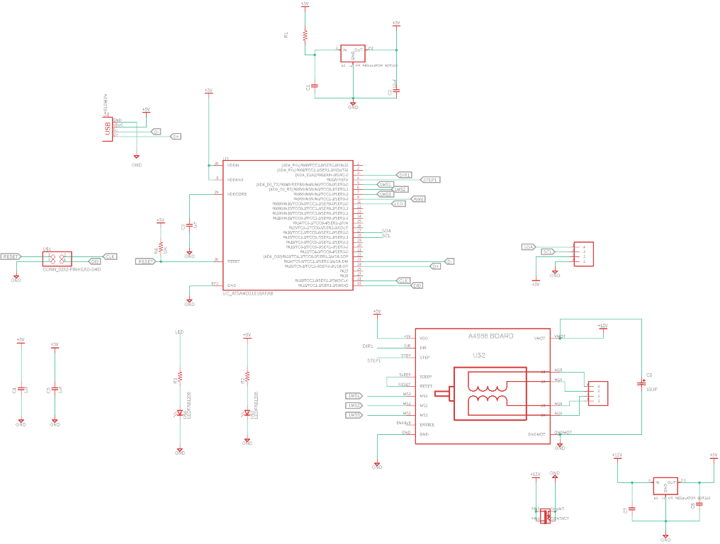
PCB layout
.png)
Milling the board
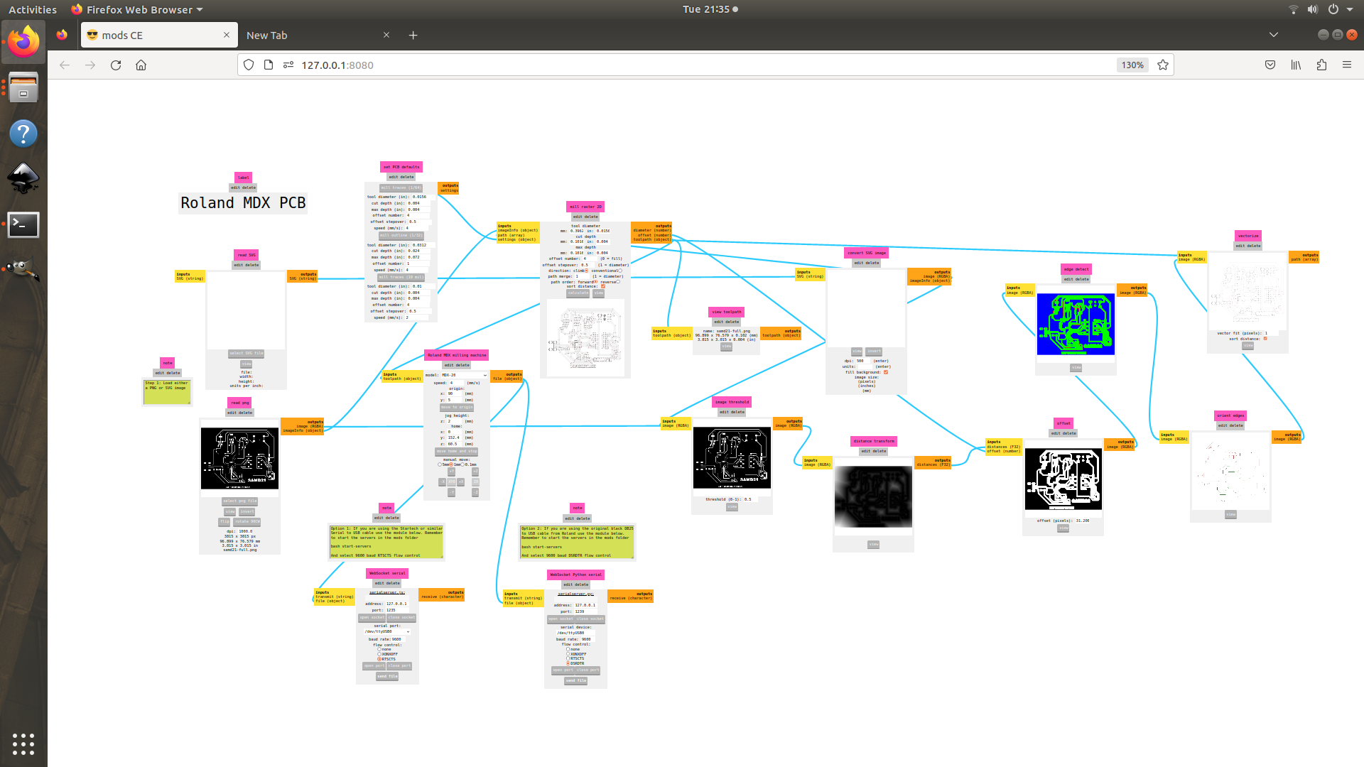
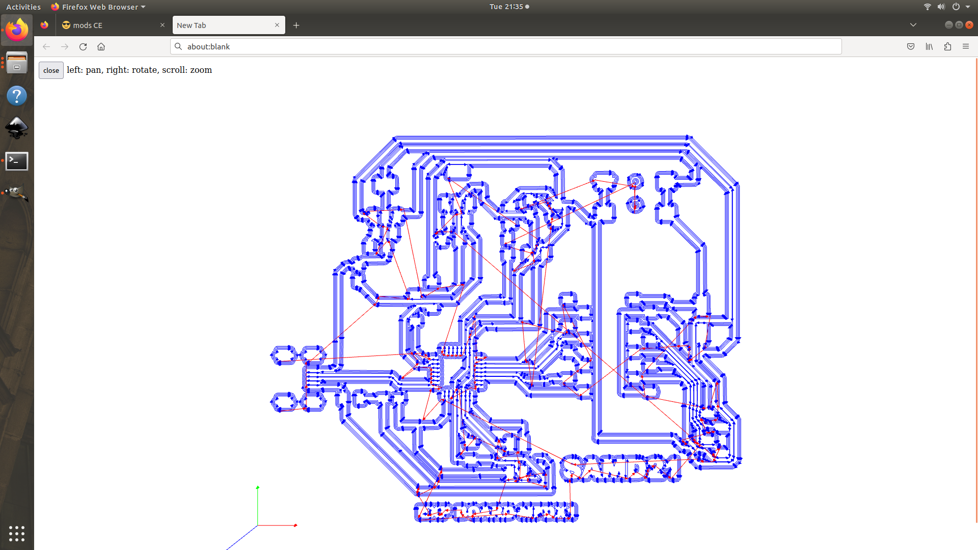
- using mods made the setup for milling
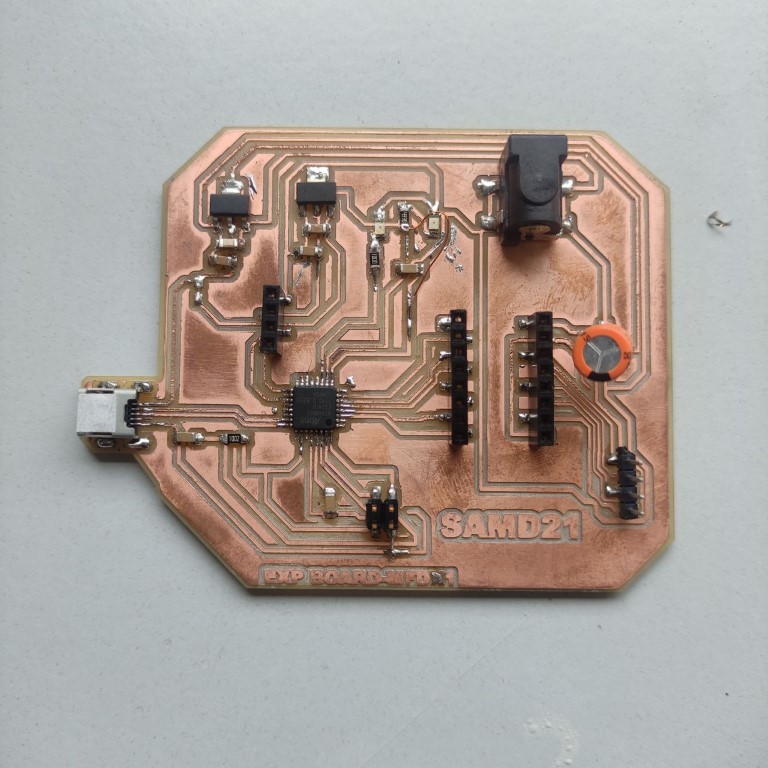
Vola, the board is now completely soldered.
Programming the SAMD21 board I made
for programming the board I made we need an SWD programmer, which we made first.
- now connect the programmer to the laptop
- and now power the SAMD21 board connecting to a power source
- before bootloading, install the required libraries

copy and paste this link to the preferences
copy this <- https://raw.githubusercontent.com/qbolsee/ArduinoCore-fab-sam/master/json/package_Fab_SAM_index.json

installing the Fab SAM core for Arduino
- after installing all the libraries, its time to load the bootloader
- use generic x21E as the board,
- the board is now connected to arduino

Blinking the LED for checking the board functions
- use the example sketch to blink the LED
void setup() {
  pinMode(11, OUTPUT);
}
void loop() {
  digitalWrite(11, HIGH);
  delay(1000);
  digitalWrite(11, LOW);
  delay(1000);
}
the board is working,
- this is the correct pin mapping use this while coding

stepper motor
- code for turning the stepper motor
// Define pin connections & motor's steps per revolution
#define dirPin 2
#define stepPin 3

//micro stepping pins
#define MS1 6
#define MS2 5
#define MS3 4


const int stepsPerRevolution = 800;

void setup() {
  // Declare pins as Outputs
  pinMode(stepPin, OUTPUT);
  pinMode(dirPin, OUTPUT);

  //declaring microstepping pins as output
  pinMode(MS1, OUTPUT);
  pinMode(MS2, OUTPUT);
  pinMode(MS3, OUTPUT);


  //enabling 1/16 microstepping
  digitalWrite(MS1, HIGH);
  digitalWrite(MS2, HIGH);
  // digitalWrite(MS3, HIGH);
}
void loop() {
  // Set motor direction clockwise
  digitalWrite(dirPin, HIGH);

  // Spin motor slowly
  for (int x = 0; x < stepsPerRevolution; x++) {
    digitalWrite(stepPin, HIGH);
    delayMicroseconds(2000);
    digitalWrite(stepPin, LOW);
    delayMicroseconds(2000);
  }
  delay(1000);  // Wait a second

  // Set motor direction counterclockwise
  digitalWrite(dirPin, LOW);

  // Spin motor quickly
  for (int x = 0; x < stepsPerRevolution; x++) {
    digitalWrite(stepPin, HIGH);
    delayMicroseconds(1000);
    digitalWrite(stepPin, LOW);
    delayMicroseconds(1000);
  }
  delay(1000);  // Wait a second
}
- turning the motor with the above code
- This is the 1.3inch-SH1106-OLED that I used
- this OLED display uses an I2C connection because it uses an I2C interface for communication with the microcontroller.
- By using an I2C interface, the OLED display can be connected to the microcontroller using just two wires (SDA and SCL), which simplifies the wiring and reduces the number of pins required on the microcontroller. Additionally, the I2C interface allows the microcontroller to communicate with multiple devices on the same bus, which can be useful for building complex systems with multiple sensors and displays.
- the I2C protocol specifies how data is transmitted and received over these lines.
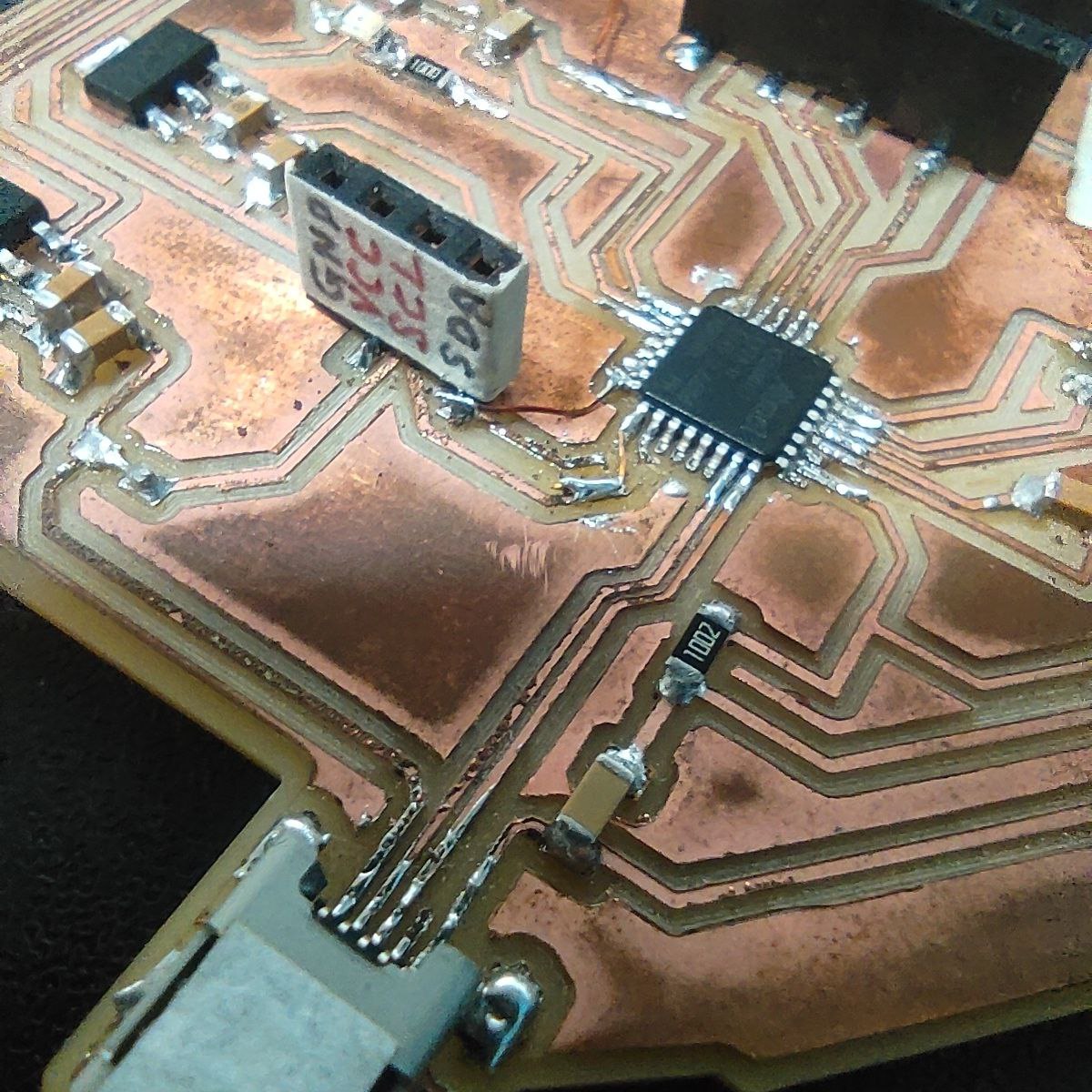
- here I have designed the board for easy plugging the display directly into the board.
- this display has SSD1306 drivers, so install the libraries for that
- also, copy and paste this “https://github.com/adafruit/Adafruit-GFX-Library” in the preferences tab of Arduino ide for more graphic options
- code for DISPLAY
CODE- ( Click to drop down)
#include <SPI.h> #include <Wire.h> #include <Adafruit_GFX.h> #include <Adafruit_SSD1306.h> #define SCREEN_WIDTH 128 // OLED display width, in pixels #define SCREEN_HEIGHT 32 // OLED display height, in pixels // Declaration for an SSD1306 display connected to I2C (SDA, SCL pins) // The pins for I2C are defined by the Wire-library. // On an arduino UNO: A4(SDA), A5(SCL) // On an arduino MEGA 2560: 20(SDA), 21(SCL) // On an arduino LEONARDO: 2(SDA), 3(SCL), ... #define OLED_RESET -1 // Reset pin # (or -1 if sharing Arduino reset pin) #define SCREEN_ADDRESS 0x3C ///< See datasheet for Address; 0x3D for 128x64, 0x3C for 128x32 Adafruit_SSD1306 display(SCREEN_WIDTH, SCREEN_HEIGHT, &Wire, OLED_RESET); #define NUMFLAKES 10 // Number of snowflakes in the animation example #define LOGO_HEIGHT 16 #define LOGO_WIDTH 16 static const unsigned char PROGMEM logo_bmp[] = { 0b00000000, 0b11000000, 0b00000001, 0b11000000, 0b00000001, 0b11000000, 0b00000011, 0b11100000, 0b11110011, 0b11100000, 0b11111110, 0b11111000, 0b01111110, 0b11111111, 0b00110011, 0b10011111, 0b00011111, 0b11111100, 0b00001101, 0b01110000, 0b00011011, 0b10100000, 0b00111111, 0b11100000, 0b00111111, 0b11110000, 0b01111100, 0b11110000, 0b01110000, 0b01110000, 0b00000000, 0b00110000 }; void setup() { Serial.begin(9600); // SSD1306_SWITCHCAPVCC = generate display voltage from 3.3V internally if(!display.begin(SSD1306_SWITCHCAPVCC, SCREEN_ADDRESS)) { Serial.println(F("SSD1306 allocation failed")); for(;;); // Don't proceed, loop forever } // Show initial display buffer contents on the screen -- // the library initializes this with an Adafruit splash screen. display.display(); delay(2000); // Pause for 2 seconds // Clear the buffer display.clearDisplay(); // Draw a single pixel in white display.drawPixel(10, 10, SSD1306_WHITE); // Show the display buffer on the screen. You MUST call display() after // drawing commands to make them visible on screen! display.display(); delay(2000); // display.display() is NOT necessary after every single drawing command, // unless that's what you want...rather, you can batch up a bunch of // drawing operations and then update the screen all at once by calling // display.display(). These examples demonstrate both approaches... testdrawline(); // Draw many lines testdrawrect(); // Draw rectangles (outlines) testfillrect(); // Draw rectangles (filled) testdrawcircle(); // Draw circles (outlines) testfillcircle(); // Draw circles (filled) testdrawroundrect(); // Draw rounded rectangles (outlines) testfillroundrect(); // Draw rounded rectangles (filled) testdrawtriangle(); // Draw triangles (outlines) testfilltriangle(); // Draw triangles (filled) testdrawchar(); // Draw characters of the default font testdrawstyles(); // Draw 'stylized' characters testscrolltext(); // Draw scrolling text testdrawbitmap(); // Draw a small bitmap image // Invert and restore display, pausing in-between display.invertDisplay(true); delay(1000); display.invertDisplay(false); delay(1000); testanimate(logo_bmp, LOGO_WIDTH, LOGO_HEIGHT); // Animate bitmaps } void loop() { } void testdrawline() { int16_t i; display.clearDisplay(); // Clear display buffer for(i=0; i<display.width(); i+=4) { display.drawLine(0, 0, i, display.height()-1, SSD1306_WHITE); display.display(); // Update screen with each newly-drawn line delay(1); } for(i=0; i<display.height(); i+=4) { display.drawLine(0, 0, display.width()-1, i, SSD1306_WHITE); display.display(); delay(1); } delay(250); display.clearDisplay(); for(i=0; i<display.width(); i+=4) { display.drawLine(0, display.height()-1, i, 0, SSD1306_WHITE); display.display(); delay(1); } for(i=display.height()-1; i>=0; i-=4) { display.drawLine(0, display.height()-1, display.width()-1, i, SSD1306_WHITE); display.display(); delay(1); } delay(250); display.clearDisplay(); for(i=display.width()-1; i>=0; i-=4) { display.drawLine(display.width()-1, display.height()-1, i, 0, SSD1306_WHITE); display.display(); delay(1); } for(i=display.height()-1; i>=0; i-=4) { display.drawLine(display.width()-1, display.height()-1, 0, i, SSD1306_WHITE); display.display(); delay(1); } delay(250); display.clearDisplay(); for(i=0; i<display.height(); i+=4) { display.drawLine(display.width()-1, 0, 0, i, SSD1306_WHITE); display.display(); delay(1); } for(i=0; i<display.width(); i+=4) { display.drawLine(display.width()-1, 0, i, display.height()-1, SSD1306_WHITE); display.display(); delay(1); } delay(2000); // Pause for 2 seconds } void testdrawrect(void) { display.clearDisplay(); for(int16_t i=0; i<display.height()/2; i+=2) { display.drawRect(i, i, display.width()-2*i, display.height()-2*i, SSD1306_WHITE); display.display(); // Update screen with each newly-drawn rectangle delay(1); } delay(2000); } void testfillrect(void) { display.clearDisplay(); for(int16_t i=0; i<display.height()/2; i+=3) { // The INVERSE color is used so rectangles alternate white/black display.fillRect(i, i, display.width()-i*2, display.height()-i*2, SSD1306_INVERSE); display.display(); // Update screen with each newly-drawn rectangle delay(1); } delay(2000); } void testdrawcircle(void) { display.clearDisplay(); for(int16_t i=0; i<max(display.width(),display.height())/2; i+=2) { display.drawCircle(display.width()/2, display.height()/2, i, SSD1306_WHITE); display.display(); delay(1); } delay(2000); } void testfillcircle(void) { display.clearDisplay(); for(int16_t i=max(display.width(),display.height())/2; i>0; i-=3) { // The INVERSE color is used so circles alternate white/black display.fillCircle(display.width() / 2, display.height() / 2, i, SSD1306_INVERSE); display.display(); // Update screen with each newly-drawn circle delay(1); } delay(2000); } void testdrawroundrect(void) { display.clearDisplay(); for(int16_t i=0; i<display.height()/2-2; i+=2) { display.drawRoundRect(i, i, display.width()-2*i, display.height()-2*i, display.height()/4, SSD1306_WHITE); display.display(); delay(1); } delay(2000); } void testfillroundrect(void) { display.clearDisplay(); for(int16_t i=0; i<display.height()/2-2; i+=2) { // The INVERSE color is used so round-rects alternate white/black display.fillRoundRect(i, i, display.width()-2*i, display.height()-2*i, display.height()/4, SSD1306_INVERSE); display.display(); delay(1); } delay(2000); } void testdrawtriangle(void) { display.clearDisplay(); for(int16_t i=0; i<max(display.width(),display.height())/2; i+=5) { display.drawTriangle( display.width()/2 , display.height()/2-i, display.width()/2-i, display.height()/2+i, display.width()/2+i, display.height()/2+i, SSD1306_WHITE); display.display(); delay(1); } delay(2000); } void testfilltriangle(void) { display.clearDisplay(); for(int16_t i=max(display.width(),display.height())/2; i>0; i-=5) { // The INVERSE color is used so triangles alternate white/black display.fillTriangle( display.width()/2 , display.height()/2-i, display.width()/2-i, display.height()/2+i, display.width()/2+i, display.height()/2+i, SSD1306_INVERSE); display.display(); delay(1); } delay(2000); } void testdrawchar(void) { display.clearDisplay(); display.setTextSize(1); // Normal 1:1 pixel scale display.setTextColor(SSD1306_WHITE); // Draw white text display.setCursor(0, 0); // Start at top-left corner display.cp437(true); // Use full 256 char 'Code Page 437' font // Not all the characters will fit on the display. This is normal. // Library will draw what it can and the rest will be clipped. for(int16_t i=0; i<256; i++) { if(i == '\n') display.write(' '); else display.write(i); } display.display(); delay(2000); } void testdrawstyles(void) { display.clearDisplay(); display.setTextSize(1); // Normal 1:1 pixel scale display.setTextColor(SSD1306_WHITE); // Draw white text display.setCursor(0,0); // Start at top-left corner display.println(F("Hello, world!")); display.setTextColor(SSD1306_BLACK, SSD1306_WHITE); // Draw 'inverse' text display.println(3.141592); display.setTextSize(2); // Draw 2X-scale text display.setTextColor(SSD1306_WHITE); display.print(F("0x")); display.println(0xDEADBEEF, HEX); display.display(); delay(2000); } void testscrolltext(void) { display.clearDisplay(); display.setTextSize(2); // Draw 2X-scale text display.setTextColor(SSD1306_WHITE); display.setCursor(10, 0); display.println(F("scroll")); display.display(); // Show initial text delay(100); // Scroll in various directions, pausing in-between: display.startscrollright(0x00, 0x0F); delay(2000); display.stopscroll(); delay(1000); display.startscrollleft(0x00, 0x0F); delay(2000); display.stopscroll(); delay(1000); display.startscrolldiagright(0x00, 0x07); delay(2000); display.startscrolldiagleft(0x00, 0x07); delay(2000); display.stopscroll(); delay(1000); } void testdrawbitmap(void) { display.clearDisplay(); display.drawBitmap( (display.width() - LOGO_WIDTH ) / 2, (display.height() - LOGO_HEIGHT) / 2, logo_bmp, LOGO_WIDTH, LOGO_HEIGHT, 1); display.display(); delay(1000); } #define XPOS 0 // Indexes into the 'icons' array in function below #define YPOS 1 #define DELTAY 2 void testanimate(const uint8_t *bitmap, uint8_t w, uint8_t h) { int8_t f, icons[NUMFLAKES][3]; // Initialize 'snowflake' positions for(f=0; f< NUMFLAKES; f++) { icons[f][XPOS] = random(1 - LOGO_WIDTH, display.width()); icons[f][YPOS] = -LOGO_HEIGHT; icons[f][DELTAY] = random(1, 6); Serial.print(F("x: ")); Serial.print(icons[f][XPOS], DEC); Serial.print(F(" y: ")); Serial.print(icons[f][YPOS], DEC); Serial.print(F(" dy: ")); Serial.println(icons[f][DELTAY], DEC); } for(;;) { // Loop forever... display.clearDisplay(); // Clear the display buffer // Draw each snowflake: for(f=0; f< NUMFLAKES; f++) { display.drawBitmap(icons[f][XPOS], icons[f][YPOS], bitmap, w, h, SSD1306_WHITE); } display.display(); // Show the display buffer on the screen delay(200); // Pause for 1/10 second // Then update coordinates of each flake... for(f=0; f< NUMFLAKES; f++) { icons[f][YPOS] += icons[f][DELTAY]; // If snowflake is off the bottom of the screen... if (icons[f][YPOS] >= display.height()) { // Reinitialize to a random position, just off the top icons[f][XPOS] = random(1 - LOGO_WIDTH, display.width()); icons[f][YPOS] = -LOGO_HEIGHT; icons[f][DELTAY] = random(1, 6); } } } }- i was not able to run the code, the display didn't work
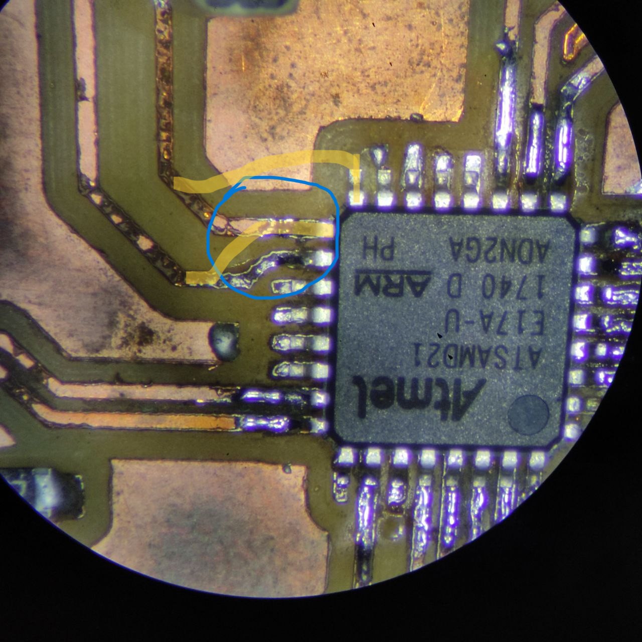
- and after some debugging found that the SDA and SCL pins are incorrect
- this is the correct pin mapping
- the yellow lines were the actual connection that has to be done
- after fixing it with copper wires
- PCB cut and PCB schematic:
placed a masking tape on the motor shaft to see the direction of the turn
OLED display as an output device
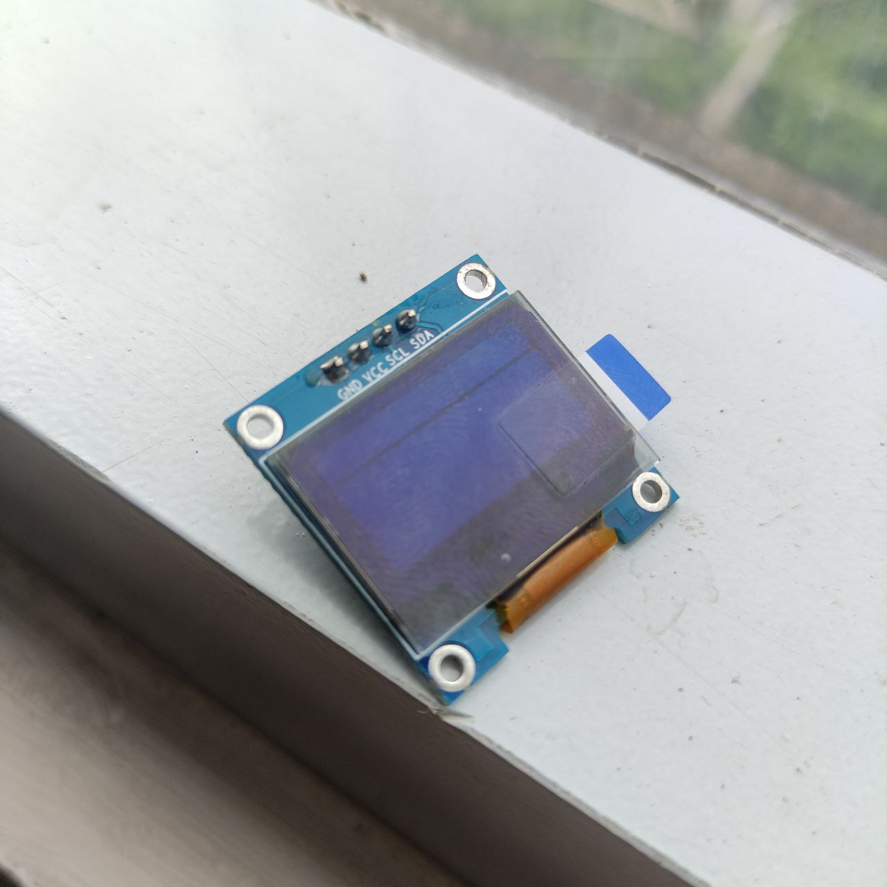

What is an I2C connection:
I2C (Inter-Integrated Circuit) is a popular communication protocol that allows multiple devices to communicate with each other using a single data line (SDA) and a single clock line (SCL). I2C is commonly used for communication between microcontrollers and peripheral devices, such as sensors, displays, and memory modules.
SDA: is the bidirectional data line used to transmit and receive data between devices in an I2C communication system.
SCL: is the clock line used to synchronize data transfer between devices. Together, SDA and SCL forms the physical communication interface for I2C communication,
Connecting
Determine the pin mapping for the OLED display. Check the datasheet or documentation for the OLED display to determine which pins are used for power, ground, and communication.
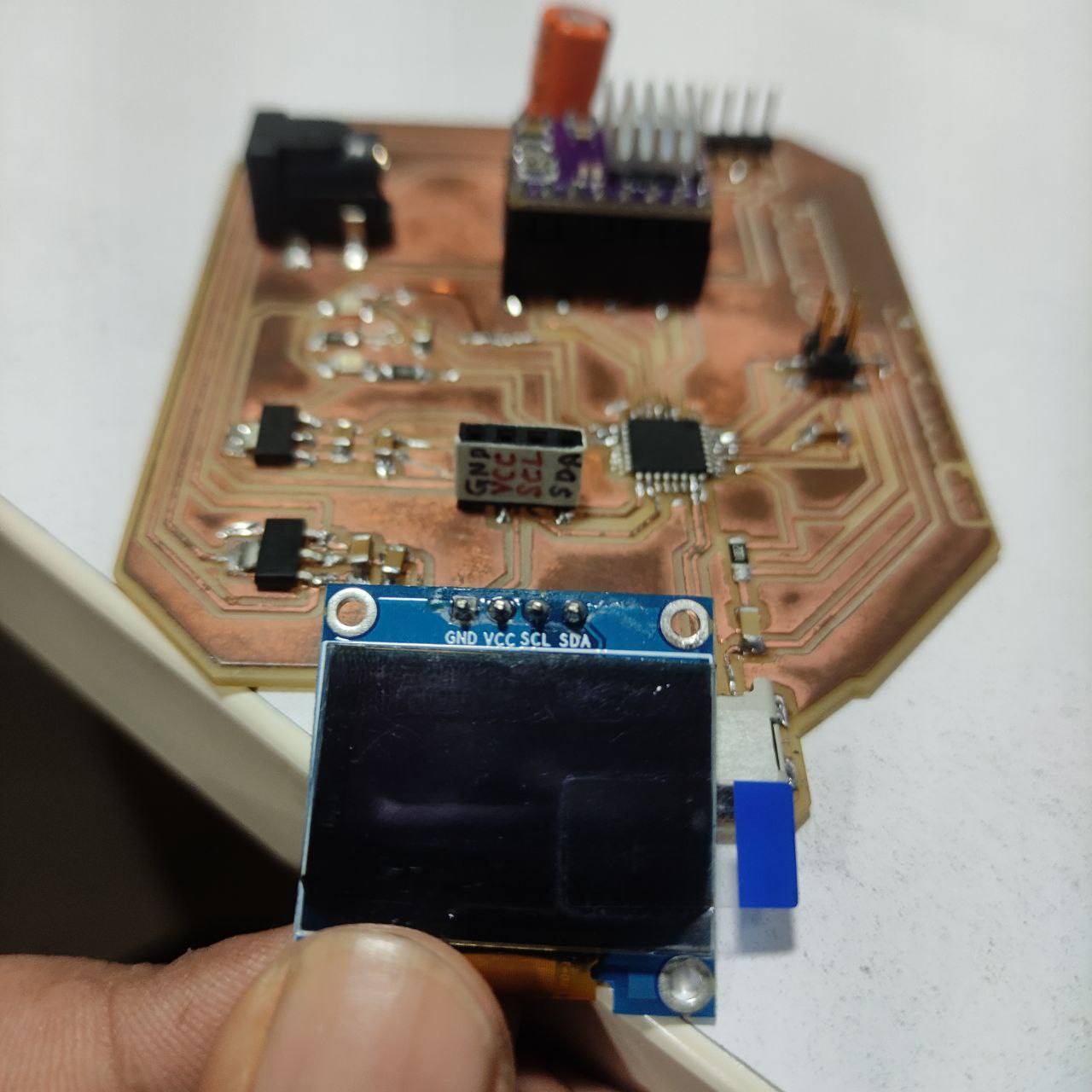
also labeled the pins for avoiding mistakes while connecting
Programming the board for OLED


Design files

.jpg)
.jpg)
.jpg)

.jpg)
.jpg)
.jpg)
.jpg)


