
Electronics Production
Objectives
Group (To redirect to the group assignment page Click here)
- characterize the design rules for your in-house PCB production process
Individual
- make an in-circuit programmer that includes a microcontroller:
- extra credit: customize the design
- mill and stuff the PCB
- test it to verify that it works
contents
milling the PCB
- designing a PCB board- done in week-6
- understanding and prepping the milling machine roland mdx
- prepping the PCB board
- connecting the milling machine using MODS
- milling the PCB
selection of components
- inventory
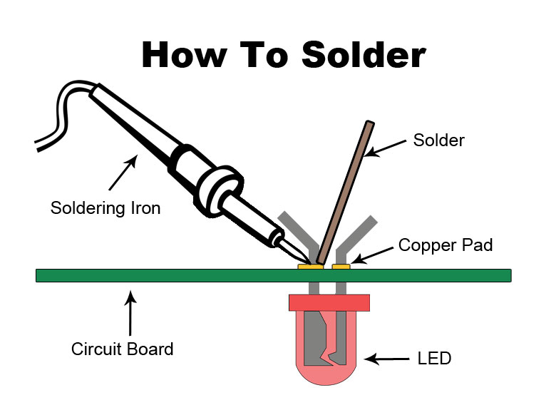
Soldering
- equipment's for soldering
- soldering practices
- soldering
Programming using Arduino ADI
PCB design
During 6th week, we have done an electronics design utilizing attiny 412. Now, In order to manufacturing it, we had to choose a suitable production method.
In the week 6, I have created a design in Fusion 360, And now i am using that design in this production week.
.png)
Production Prerequisites
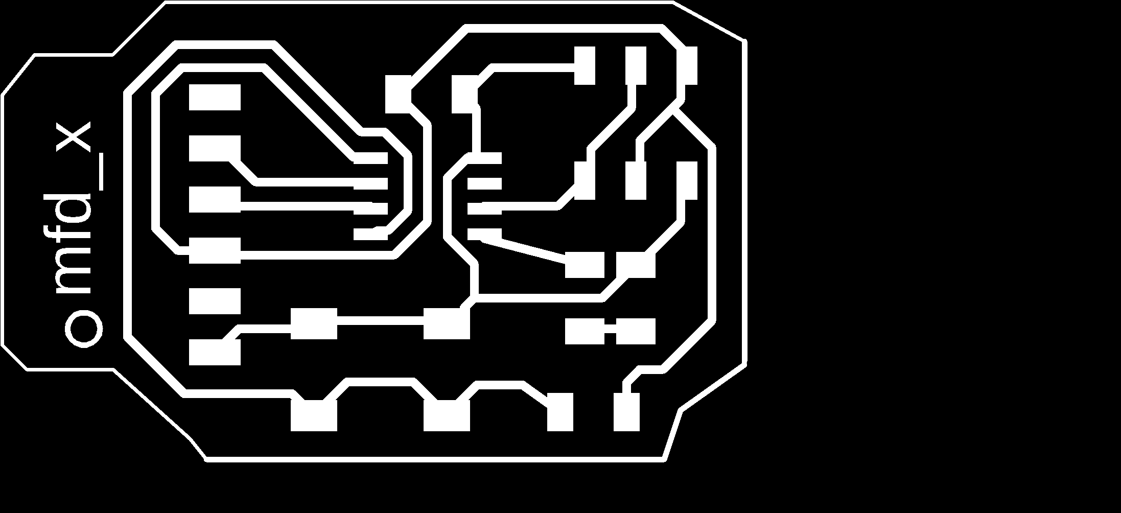
I had to export the file in the png format, in fusion 360 it was an easy process, i just had to type export in the command line
image here
image here
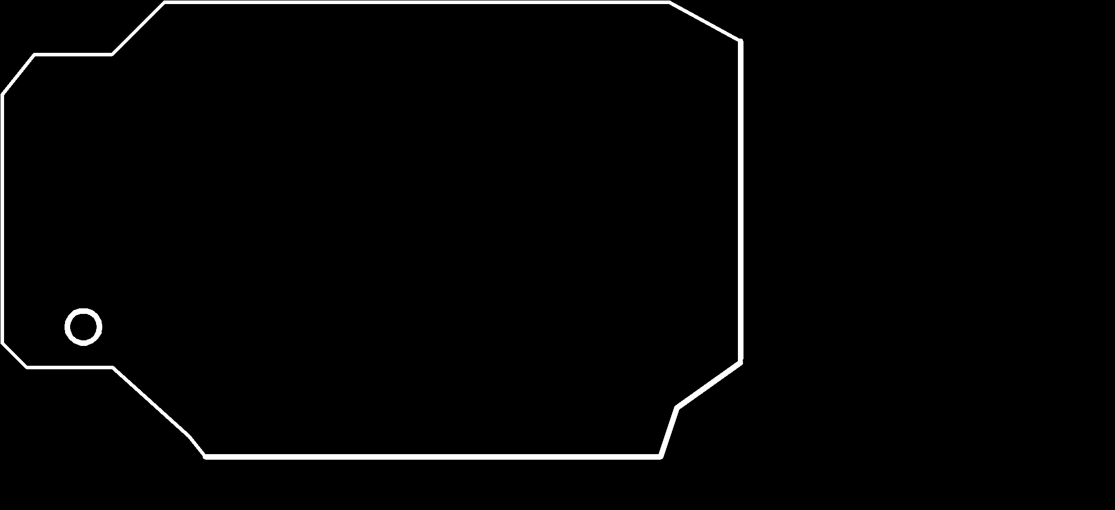
- i had to export it in two files
- the complete design
- the outer border which will be cut out from the rest of the board
The design
Milling the PCB
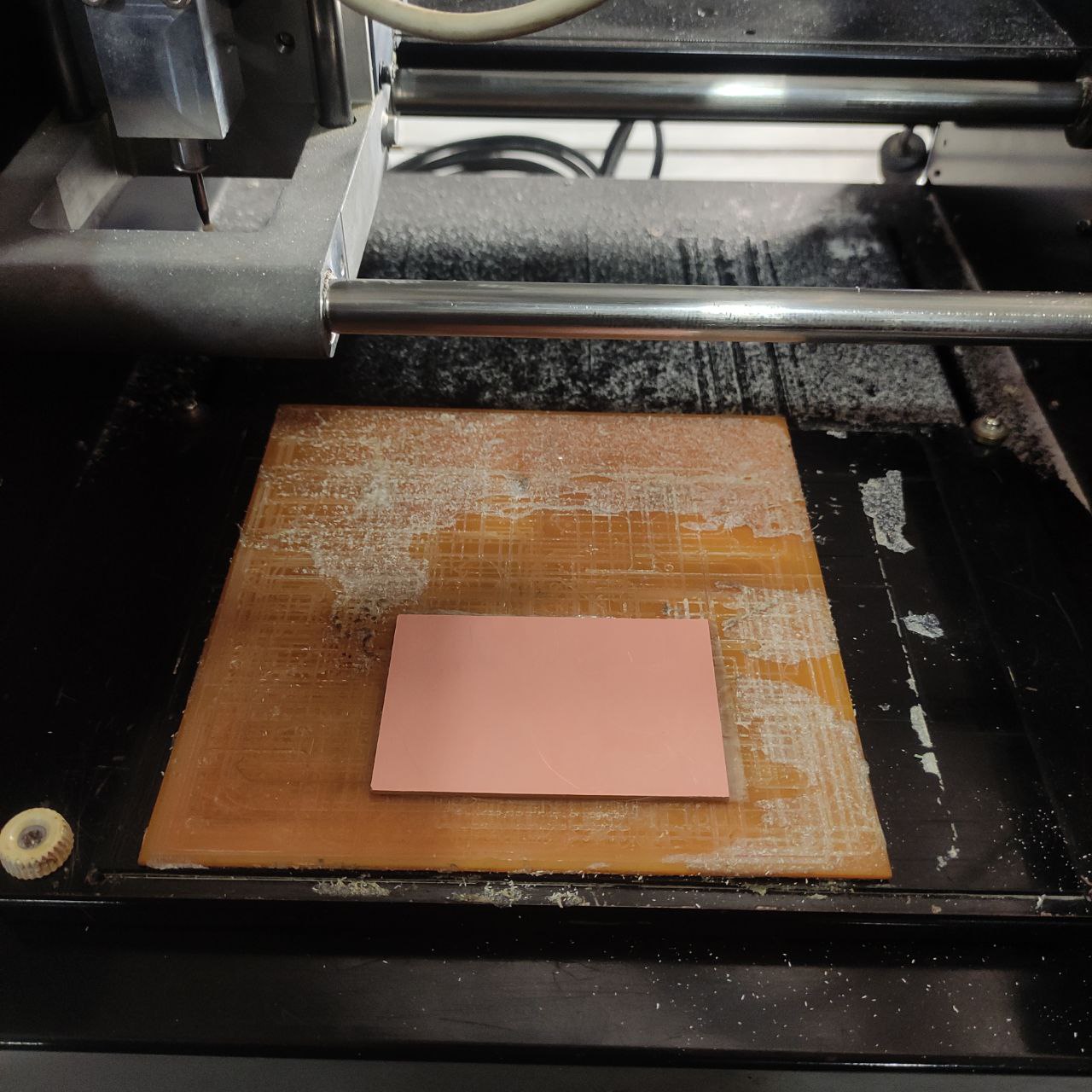
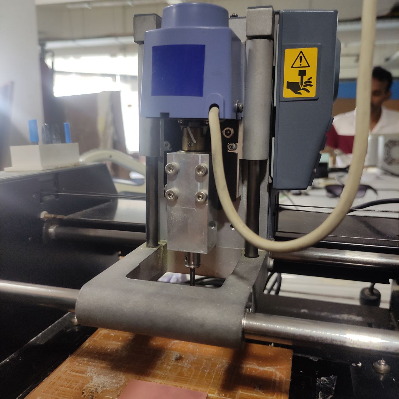
Roland Modela milling machine
The Roland Modela milling machine is a desktop-sized milling machine that is used for precision milling, drilling, and carving of a variety of materials such as plastic, wood, wax, and metal. It is manufactured by Roland DG Corporation, a Japanese manufacturer of digital fabrication tools and equipment
.jpg)
Setting up the machine
Since it is a basic milling machine we had to set it up for milling the pcb
- selection of tools
For milling the PCB we have to use 0.4 and 0.8 mm bits.
0.4mm bit for tracing the paths and 0.8mm bit for cutting the outer border
.jpg)
.jpg)
- Selection of PCB board
Here i used a stock size board of dimetions 70mm x 50mm it is a standard size
- stick a double side tape on the other side of the PCB board
- this is in order to stick the PCB to the bed of the milling machine
- stick the pcb to the bed
.jpg)
- Setting the jog height
.jpg)
.jpg)
- first loosen the Allen keys and remove the existing bit
- first we are using the 0.4mm for tracing, if we cut first the whole board will move around
- insert the bit and tighten the Allen keys
- now the move the spindle to the top of the pcb -the coordinates where 60x-15y for me
- now reduce the z height to a level where it almost touches’ the board
- loosen the bit and manually touch the board with the end of the bit
be careful as the bit is a bit expensive and might fall when loosening the allenkey, so first hold the bit and loosen the allen key, * note apply some pressure then tight the allenkey
- Move the z axis, just by one press, this is to set the origin.
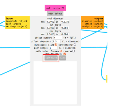
FABMOD
https://modsproject.org/ - for mods
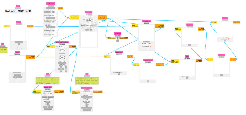
As the machine only takes input in the form of G-code, we need to convert the PNG or SVG format into G-code. Luckily, we have mods, so the PNG files can be converted into G-code using mods. In the mods, we have to change the settings according to our machine.
- We need to change the spindle RPM to 1400 RPM and the jog height to 0.5 mm. After selecting the tool for milling or cutting, we can hit calculate, and the G-code will be downloaded automatically.

.jpg)
.jpg)
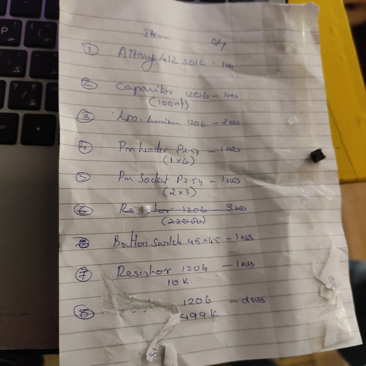
selecting the components
- since i used fusion 360 i was able to export the BOM
- From the components list I selected the components from our inventory
our inventory was large there where a lot of components, it it took a bit of time
Components list
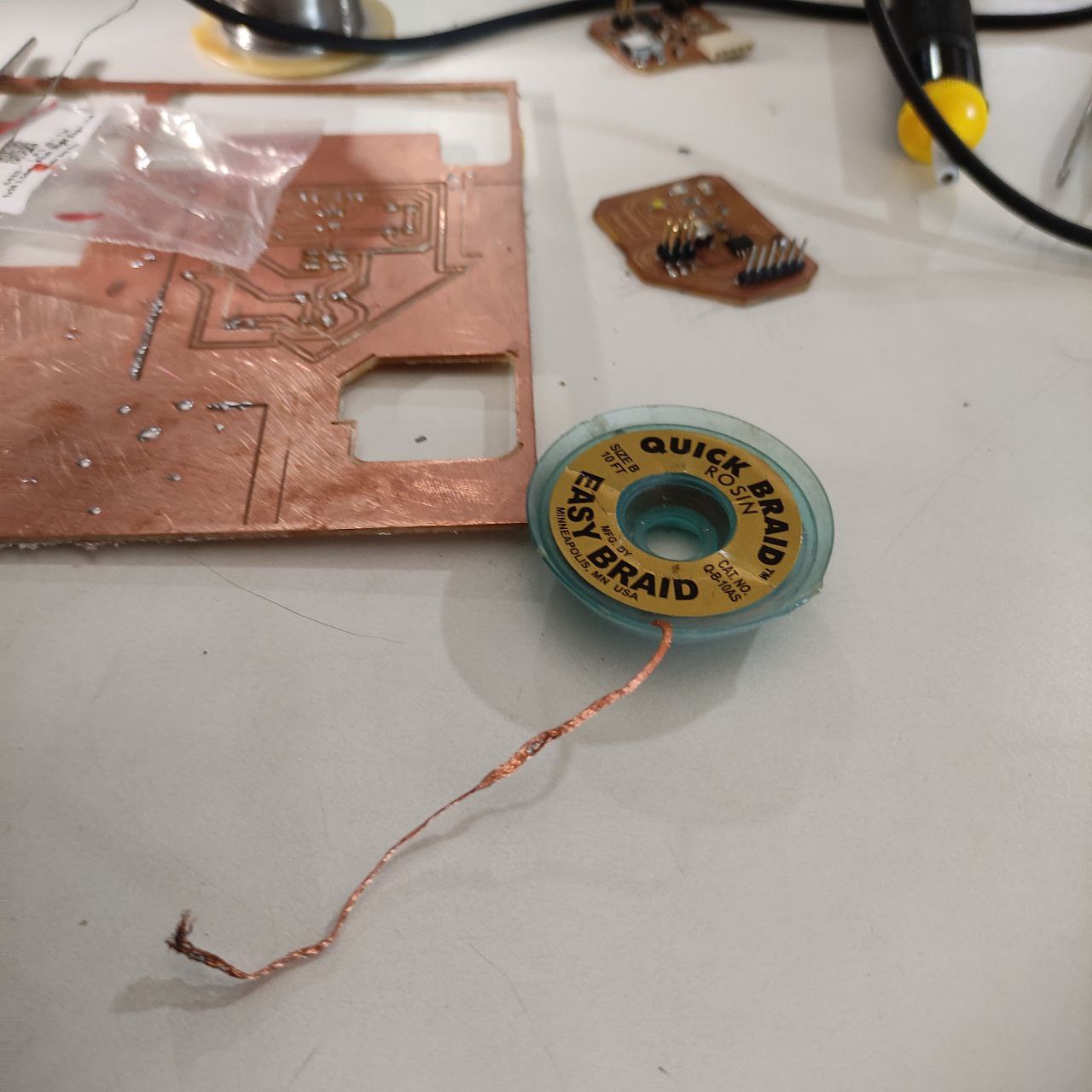
Soldering the components
The setup
.jpg)
- equipment's
Soldering practices
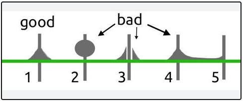
*refer this link for good soldering practices
- Here i started soldering small components first, then the smaller ones, as it would be harder to solder smaller components as it will be harder to asses the pads with larger components on top.
- started with, resistors
- capacitors
- led
- attiny
- connectors and UPID pin
.jpg)
.jpg)
.jpg)
.jpg)
Programming the board i made
Programming with Arduino IDE
- use this guide for Boards Manager Installation in arduino IDE
 https://github.com/SpenceKonde/ATTinyCore
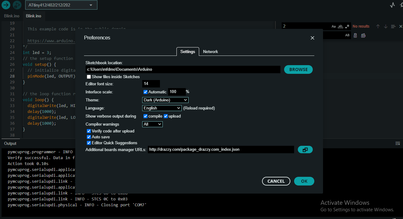
blinking the LED
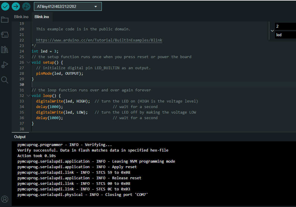
files>examples>basics>sketch
using the example code to blink the LED.
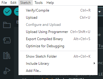
now after compiling use “upload using programmer”
.jpg)
the LED has blinked