computer-controlled machining
WEEK - 7
Objectives
- To do the lab’s safety training(Group Assignment added HERE)
- To run out, alignment, fixture, speeds, feeds, materials, and tool path for our machine(group assignment)
- To make (design and assemble) something big (on a meter-scale)
CONTENTS
Design
The idea:
to create parametric furniture that can only be made using a joints
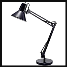
- My idea is to create a shop lamp that can be placed on the floor or table
- before designing, we have to check the available materials in the lab and make the design accordingly
- the size of the materials we had: 1220x2250 12mm ply and 8x4 feet 18mm ply
- the plywood thickness is not uniform as the plywood is locally sourced, for considering the clearance for a tight fit I will be taking the average thickness.
- clearance= 0.2
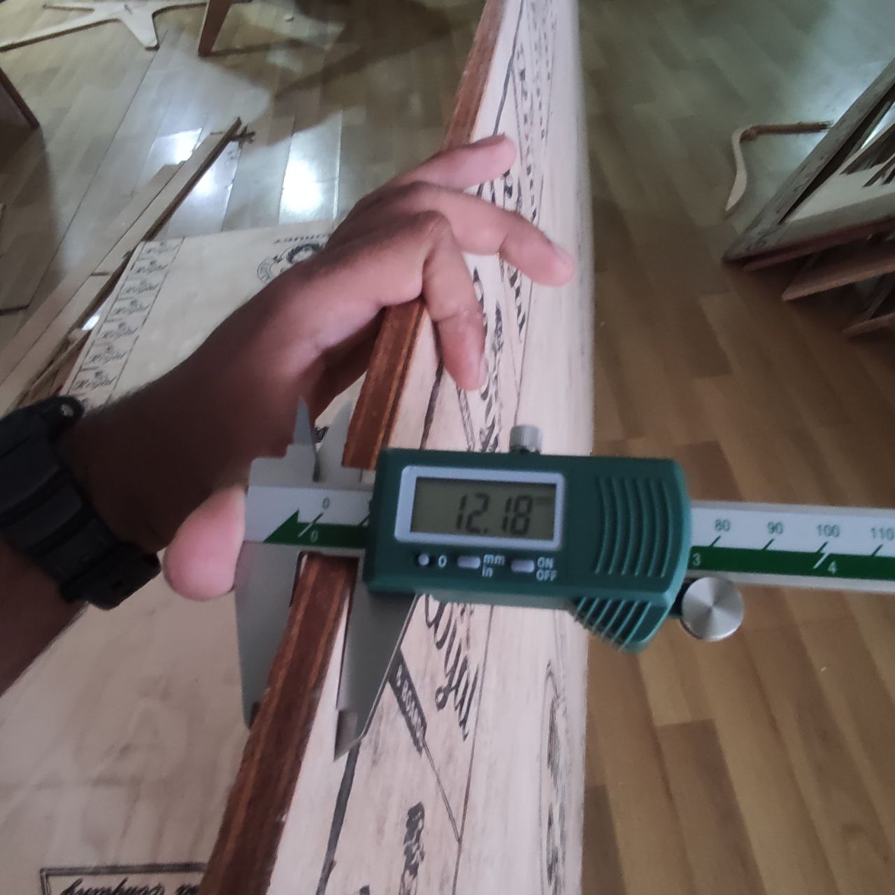
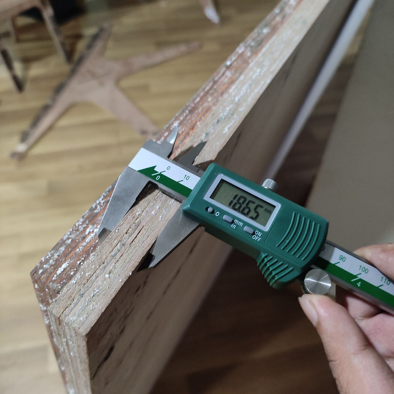
- the thickness is not same every where, so i averaged it and too 12mm and 18.6 as thickness and 0.2 as clearance
- Now we can start the design considering these values
Design in Fusion 360
I usually use Solid Works for making the designs and drawings and. As I was becoming more familiar with Fusion360, I considered the idea of using it to complete all of the design work and CAM file preparation.

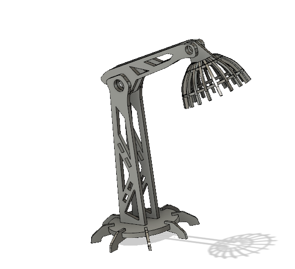
As per the instructions from my lab instructor, the design of this lamp is not in meter scale and had to consider another design
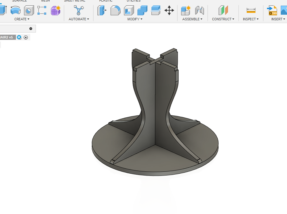
- So for the next one, I decided to design a parametric chair

parameters based on the measurements taken from the ply board we had
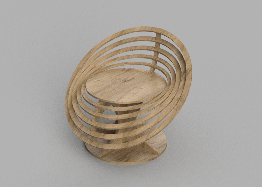
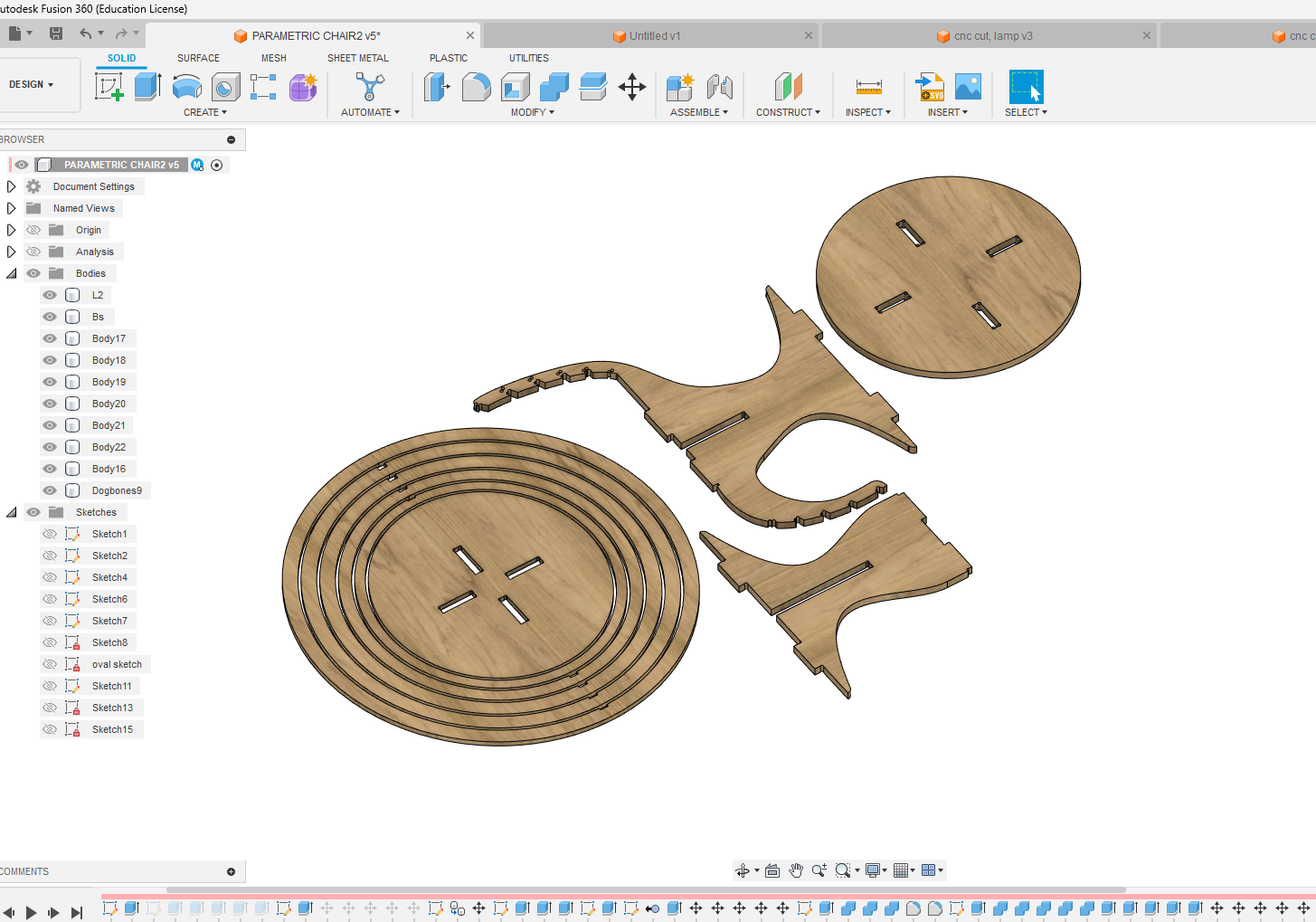
- cad designing

- Rendered image
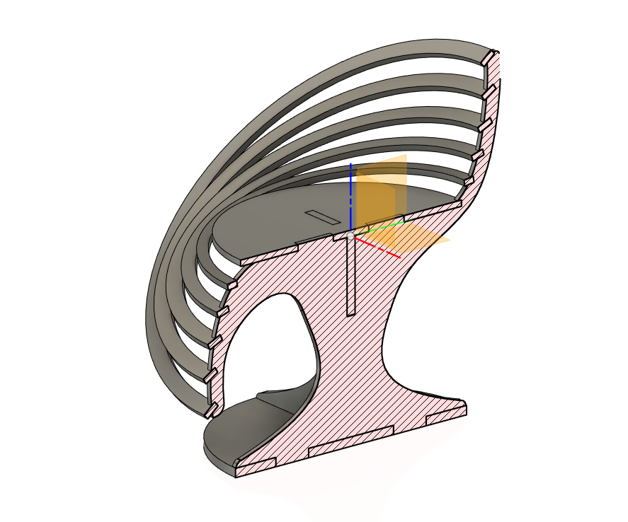
- I designed the parts with press-fit assembly in mind and then converted each part into a component. Next, using the "Arrange" tool in the toolbar, I positioned the components in a way that allowed them to be projected onto a sketch. This sketch was then imported to create the CAM file
- Within this window, there is a tab labelled "Objects" where we can choose the desired components and faces. On the "Envelopes" tab, we can then select the specific sketch onto which we want to place these objects.
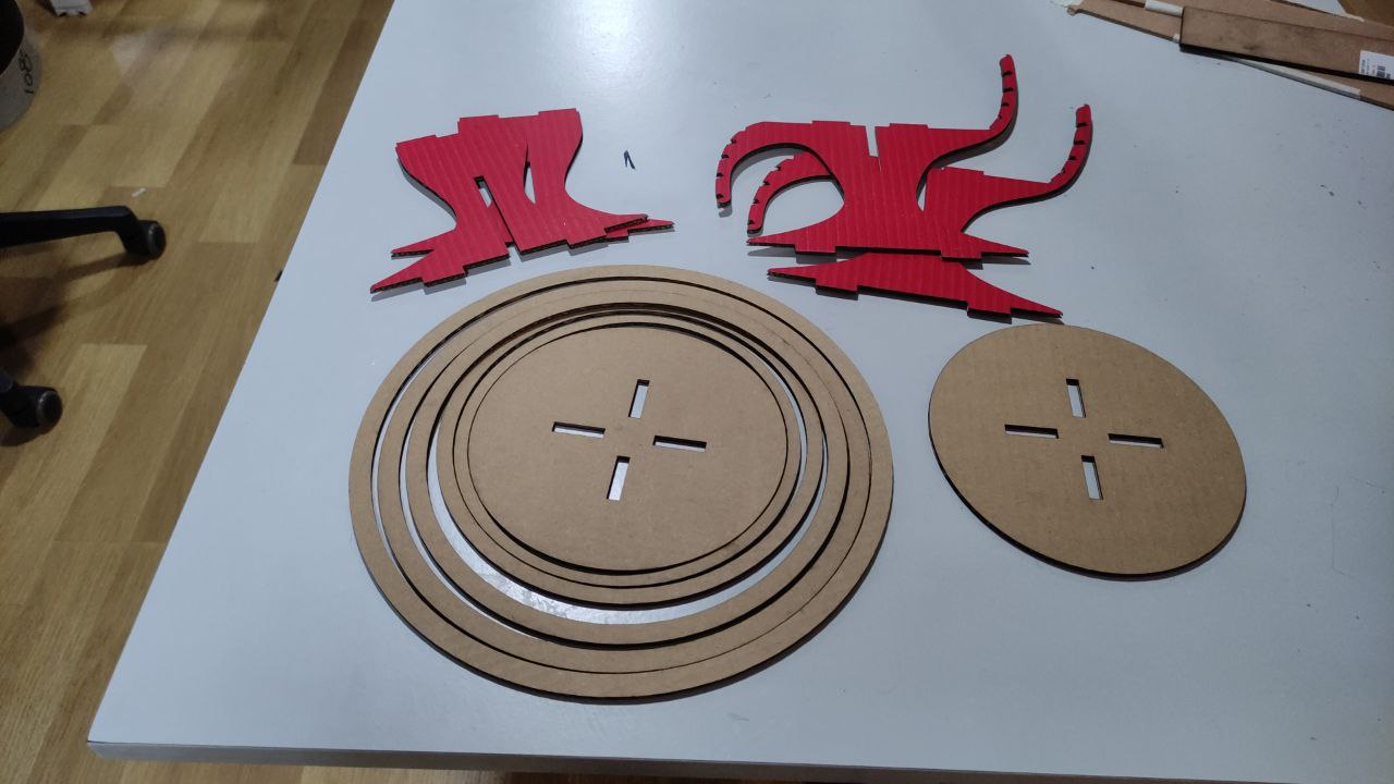
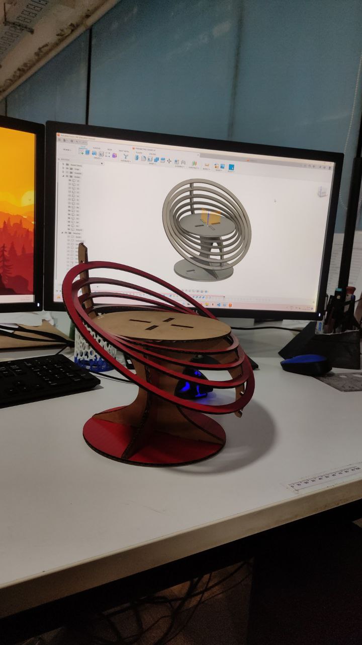
Sample model with laser cutting
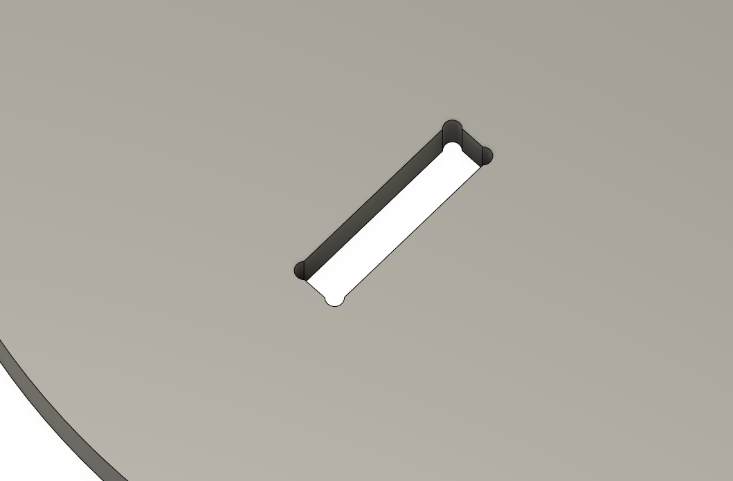
dding Dogbone
Dogbones are added to plywood CNC milling designs to account for the cutting tool's width, which can create a radius in inside corners. By adding dogbones at these corners, the tool removes a small amount of material, ensuring a tight fit between parts. Without dogbones, the parts may not fit together properly due to the radius left by the tool.
- Once I finished arranging the parts, I utilized a Dogbone plugin/extension which i found here
and added to the pockets and press-fit joints
we can download NIFTY DOGBONE plugin from here
—Adding Dog bone

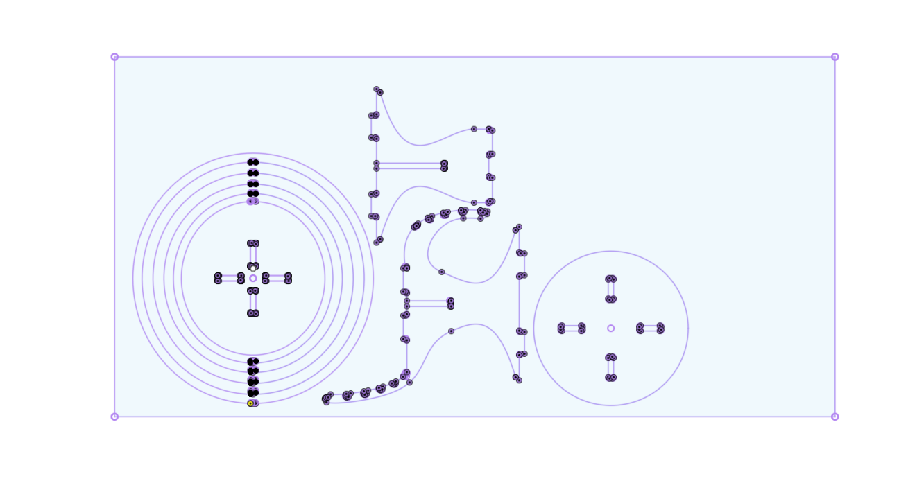
- Next, I used the "Projected" function to transfer these parts into a " .dxf" file format, which I could then import into the CAM software for preparing the necessary CAM files.
- To export the sketch as a " .dxf" file format, you can simply select the sketch and then right-click to access the export function> save as dxf
CAM using VCarve
- Then I used VCarve for making the CAM Toolpaths.
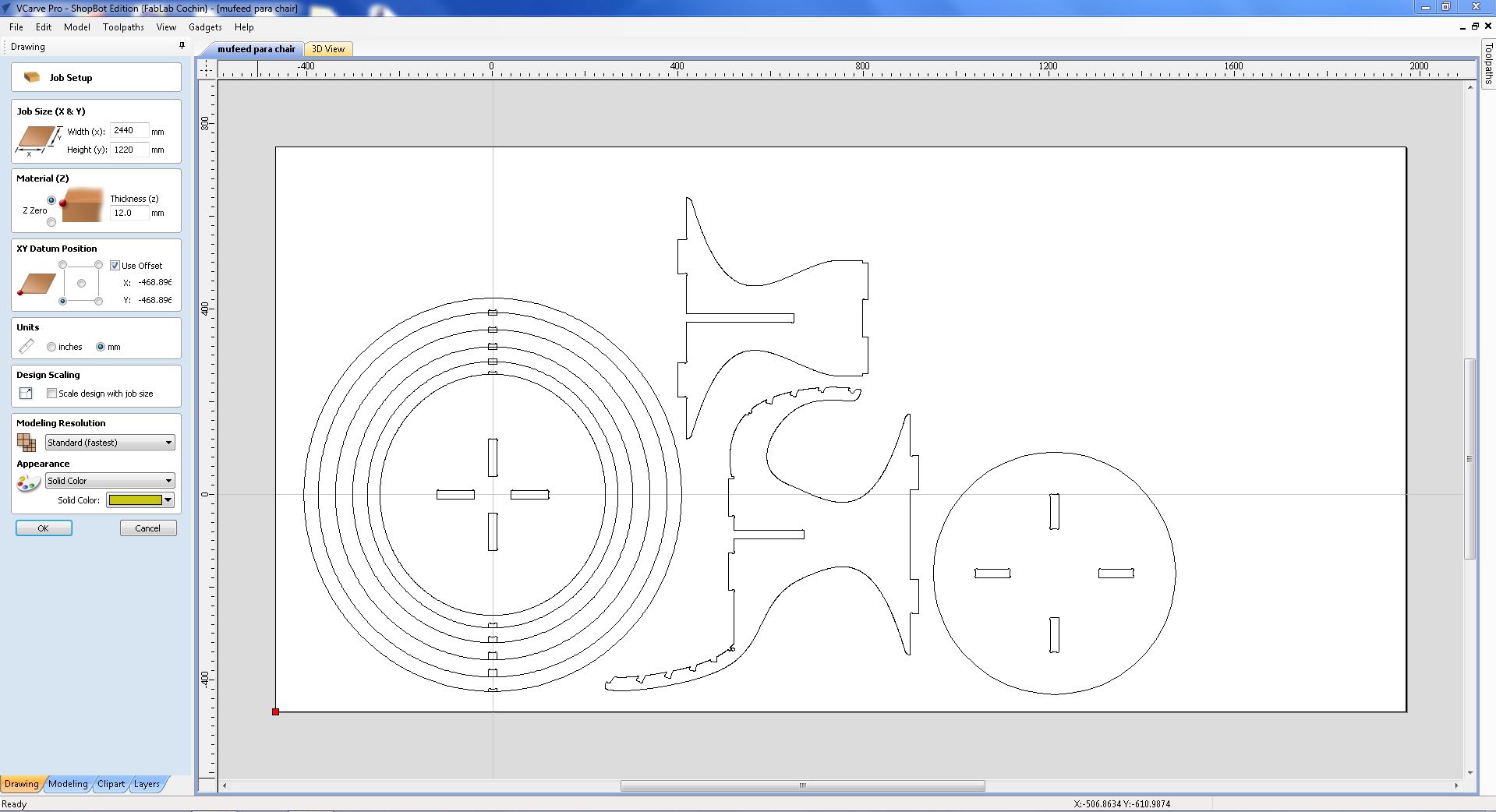
interface of the Vcarve
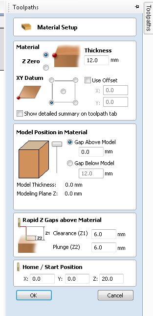
- After opening the ".dxf" file in the CAM software, we can assign material attributes such as length, width, thickness, etc. to the plywood that we plan to use.
- Using the "move," "rotate," and "flip" tools, I made adjustments to the file to ensure that each part would use the maximum amount of material possible.
- Selecting the tool
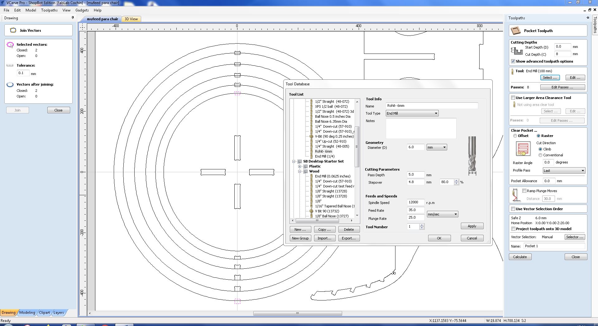
- Moving to the "Tool paths" tab on the right-hand side of the software, I began creating the necessary tool path. The first tool path I generated was for the inner holes the holes with dogbones
- Next I added the pockets for the press fit joints using the “2D Profile Tool path”
- and finally added the tool path for cutting the individual parts
- When creating tool paths, it is important to select whether you want to cut the inside or outside of the part. Always ensure that you give commands accordingly.
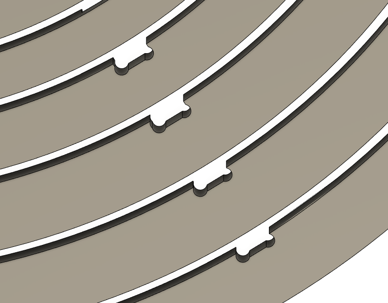
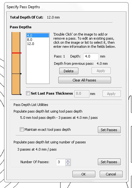
- Notice the “T” which are Tabs. During milling/cutting or when the machine finishes cutting a part there is a tendency for these parts to move around due to vibrations or other various reasons, so these tabs are added that way the pieces stay intact until the end of the milling process.
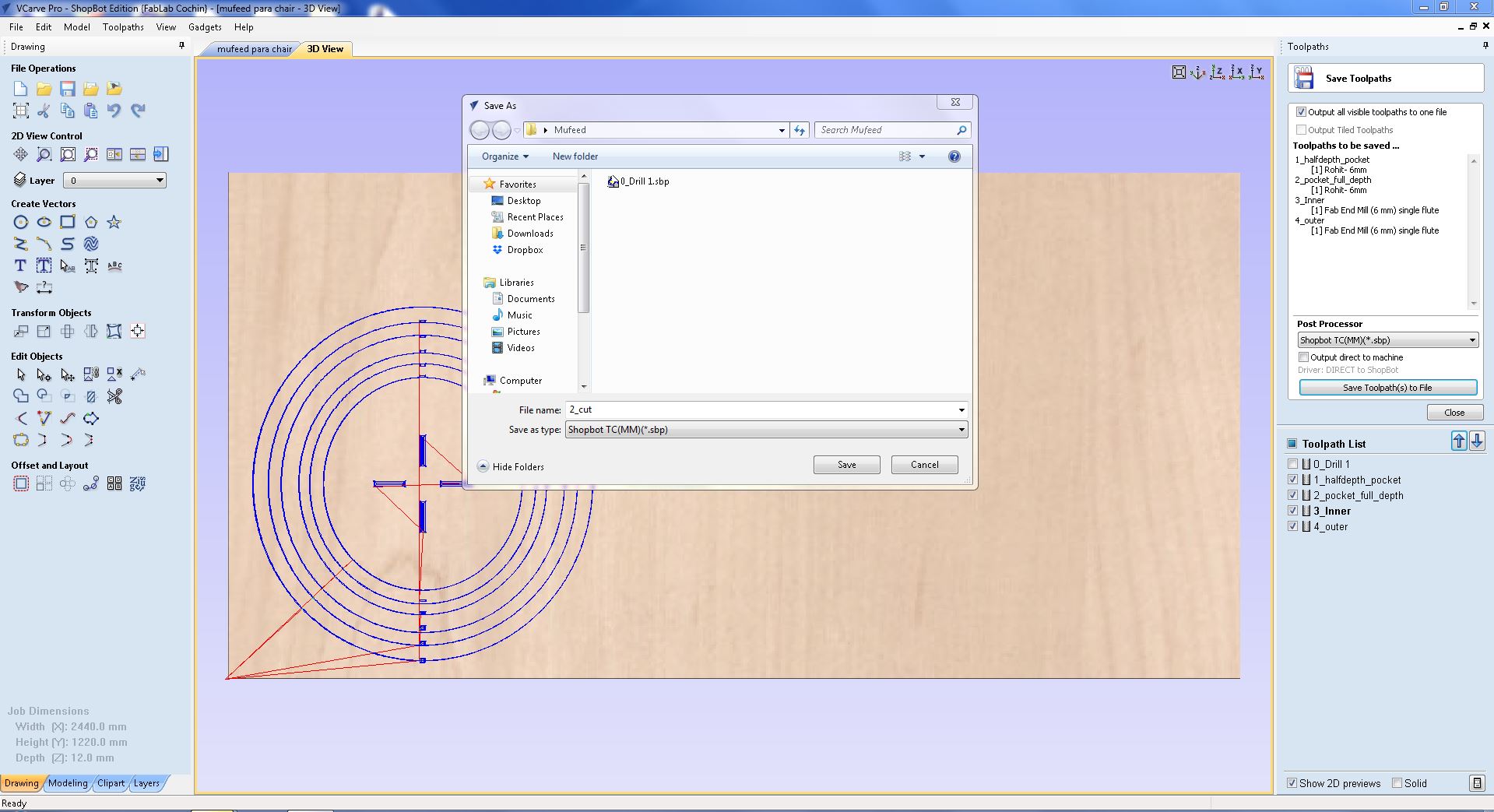
- saving the file to cut
- for me i had to use two thicknesses 3 pieces with 18mm sheet and 6 pieces with 12mm sheet
- so first i cut the 18mm sheet as there was few space left in Sreyas sheet so its better to use that so save material.
- and for the rest i used a new board.
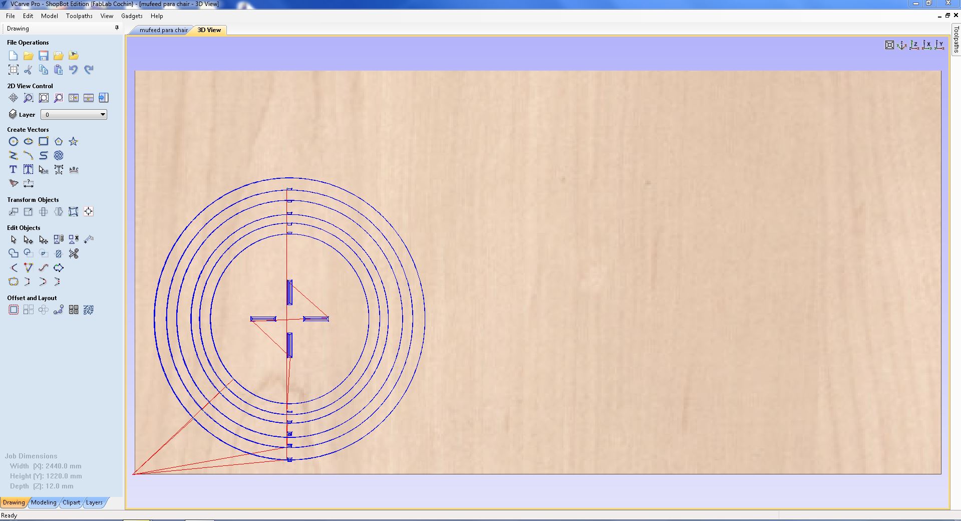
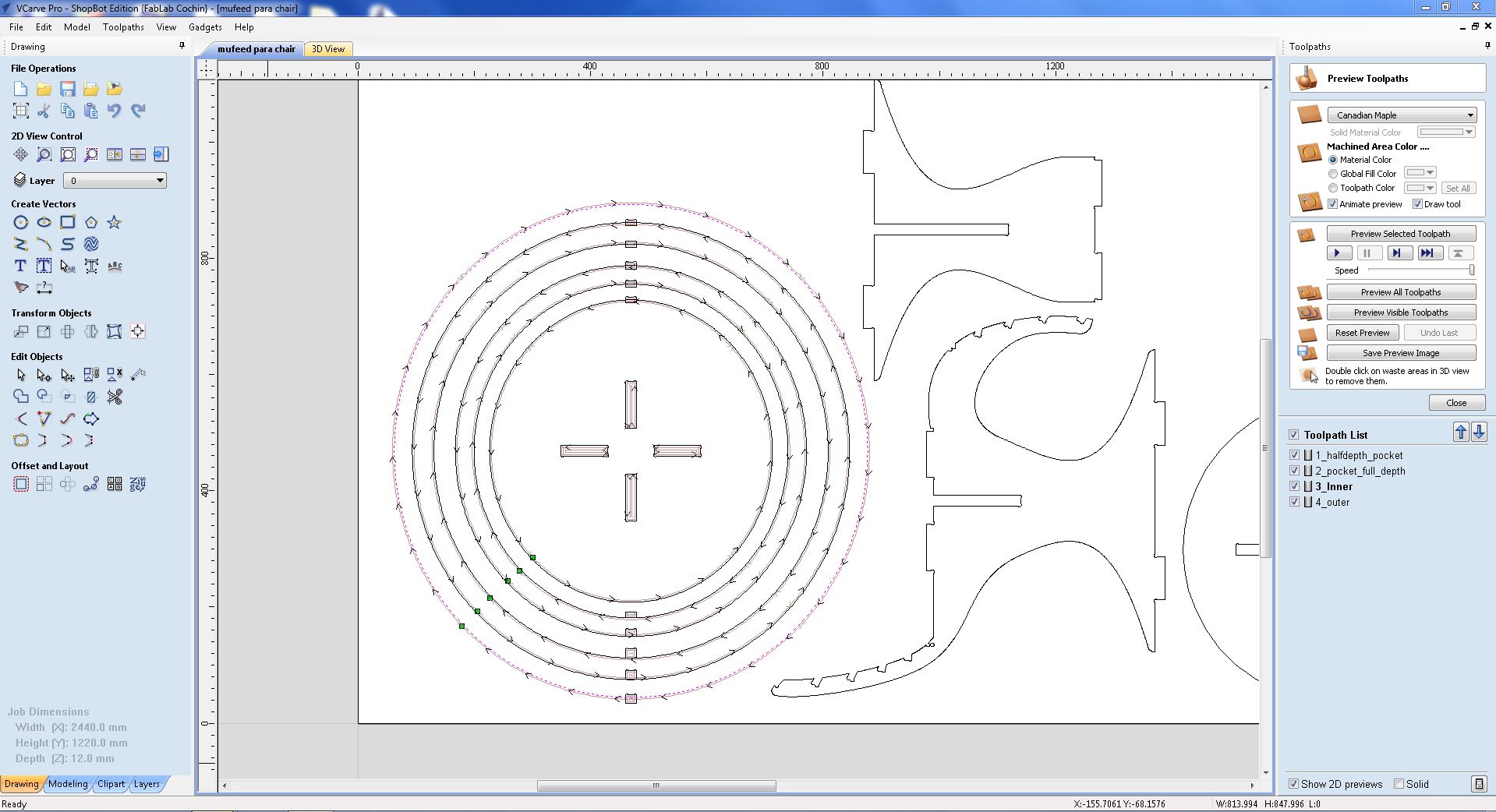
tool path for cutting in 12mm thickness sheet
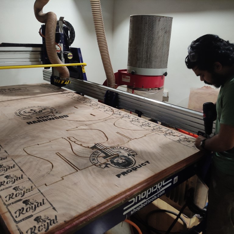
Machining
SHOP BOT PRSalpha 96 CNC Route
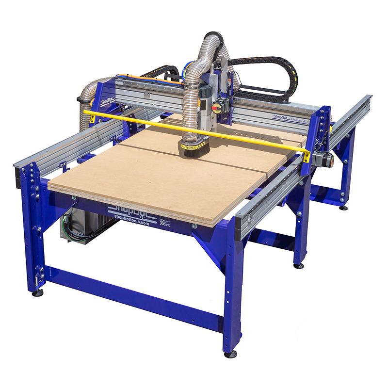
this is the machine we are using for wood working
- here is the user manual of the machine : click here
Features of the machine:
- Bed is stationary
- Spindle moves in X,Y,Z directions
- It can use for carving, cutting and engraving.
- bed size 1.7526m x 2.4384m
- Table Thickness: ¾” Plywood Bottom Layer, ¾” MDF Top Layer
- As the CAM is completed we can open the ShopBot’s Software to load the CAM toolpath and run the files

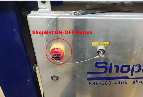
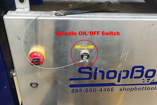
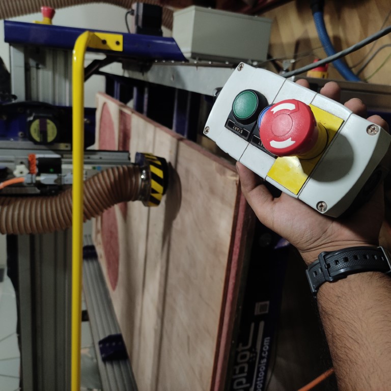
- The first step is to switch ON the ShopBot, by turning the knob found on the side panel of the ShopBot
- before cutting its imporant to clamp the plywood sheets to the Shop bot platform using screws so that they doesn't move around.
- Once the ShopBot is ON we can open up the software
- this is the Shop bot app
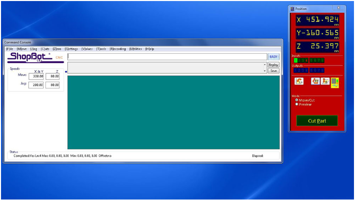
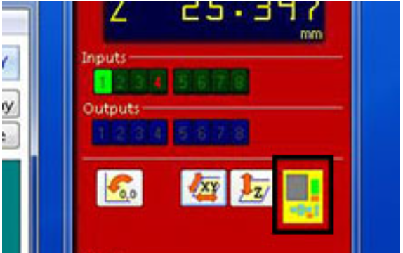
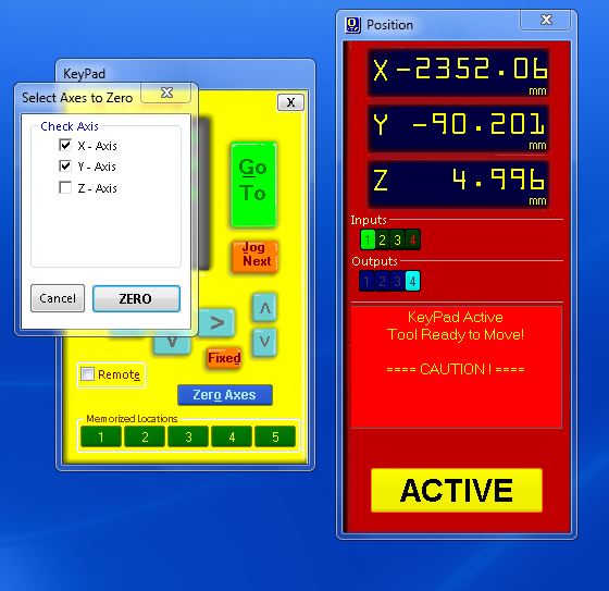
- To load our file into the ShopBot, we must first zero the machine to the origin point of our material or stock. This can be achieved by clicking on the remote icon and following the necessary steps.
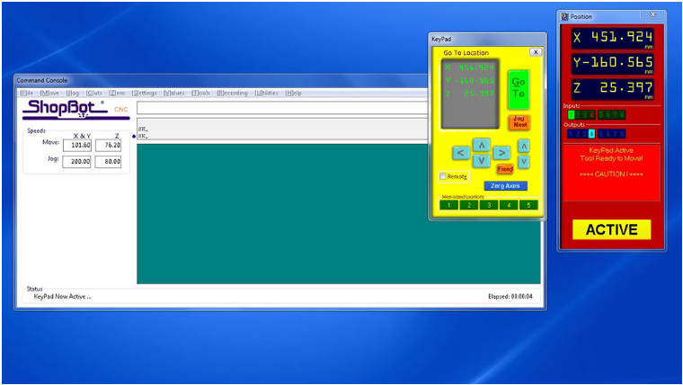
- After clicking on the remote icon, we can use the arrows on the remote or arrow keys to move the ShopBot to the origin point of our material. Once we are in position, we can click on the "Zero Axes" button and then select the axes we want to zero by clicking on the "ZERO" button. This will zero our machine and we will be ready to begin the cutting process.
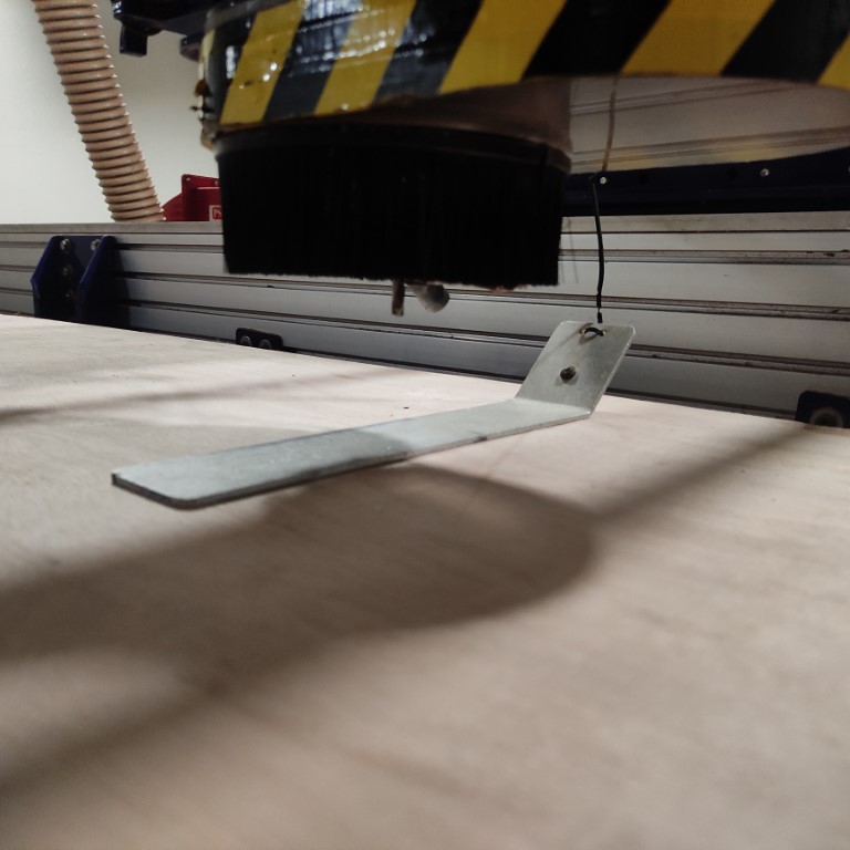
Zeroing the machine
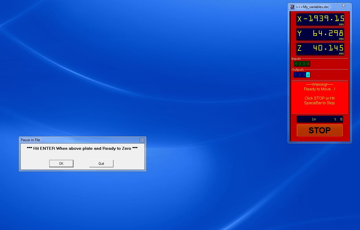
- This probe is used to zero the machine at z axis, the machine detects the position when the tool and this metal plate comes in contact, this probing plate is an additional accessory of this machine.
- check the axis's
- and now hit ender
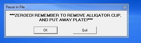
- this message will be shown when it zeroed .
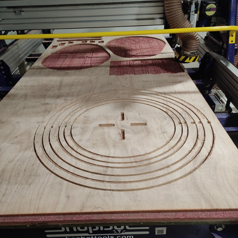
- now finally we can load our file by clicking on “Cut Part”
- once the file is uploaded we can START

- After clicking the "START" button, a window will appear requesting that we switch on the spindle. The spindle can be turned on using the key located on the side panel of the ShopBot.

- And now we also have to press the Start button on the physical remote
- Once the spindle is spinning, we can click "OK" and the Shop Bot will begin running the code line by line. The progress of the code can be viewed on the "Command Console".
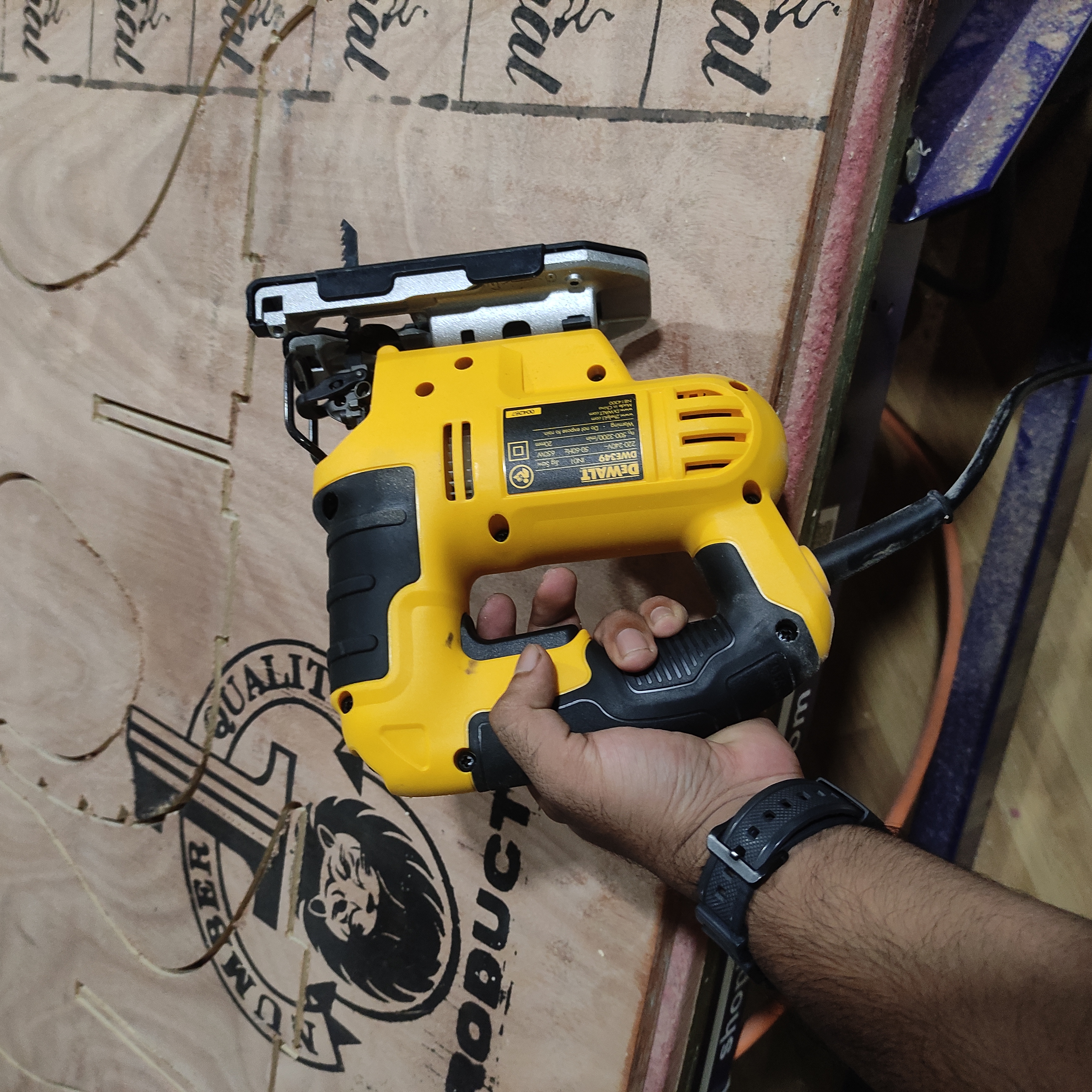
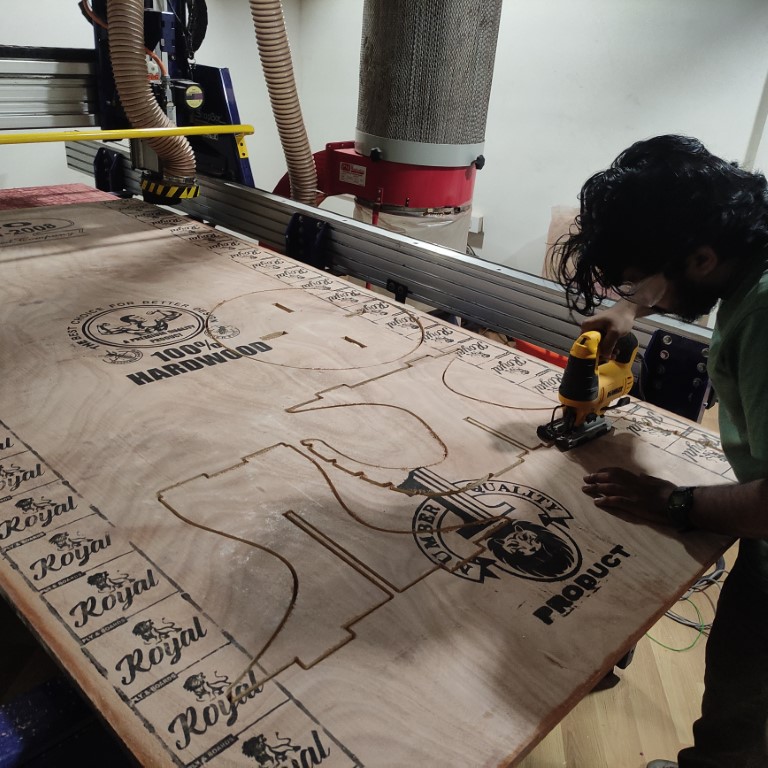
- i used this tool to cut the tabs
- Now finally assembling all the parts
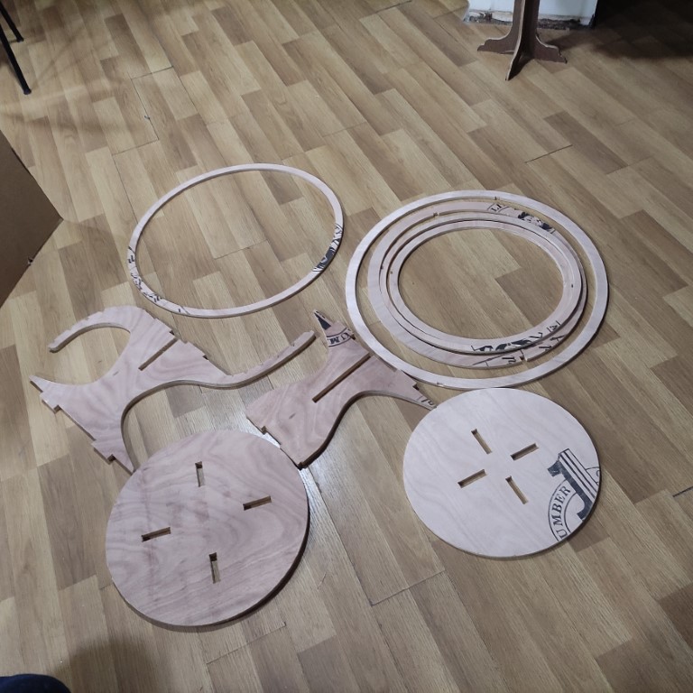
.jpg)
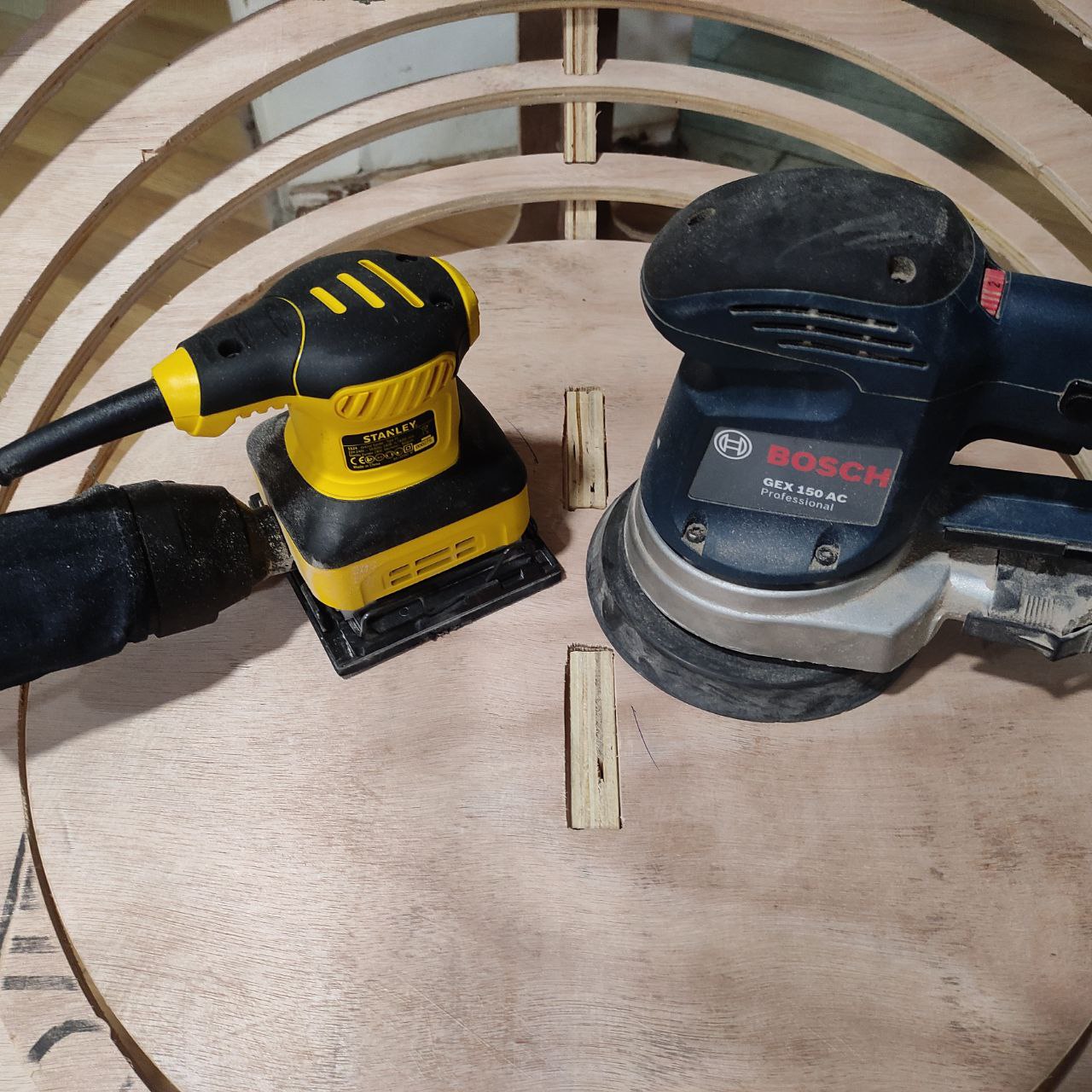
- I used these tools for sanding
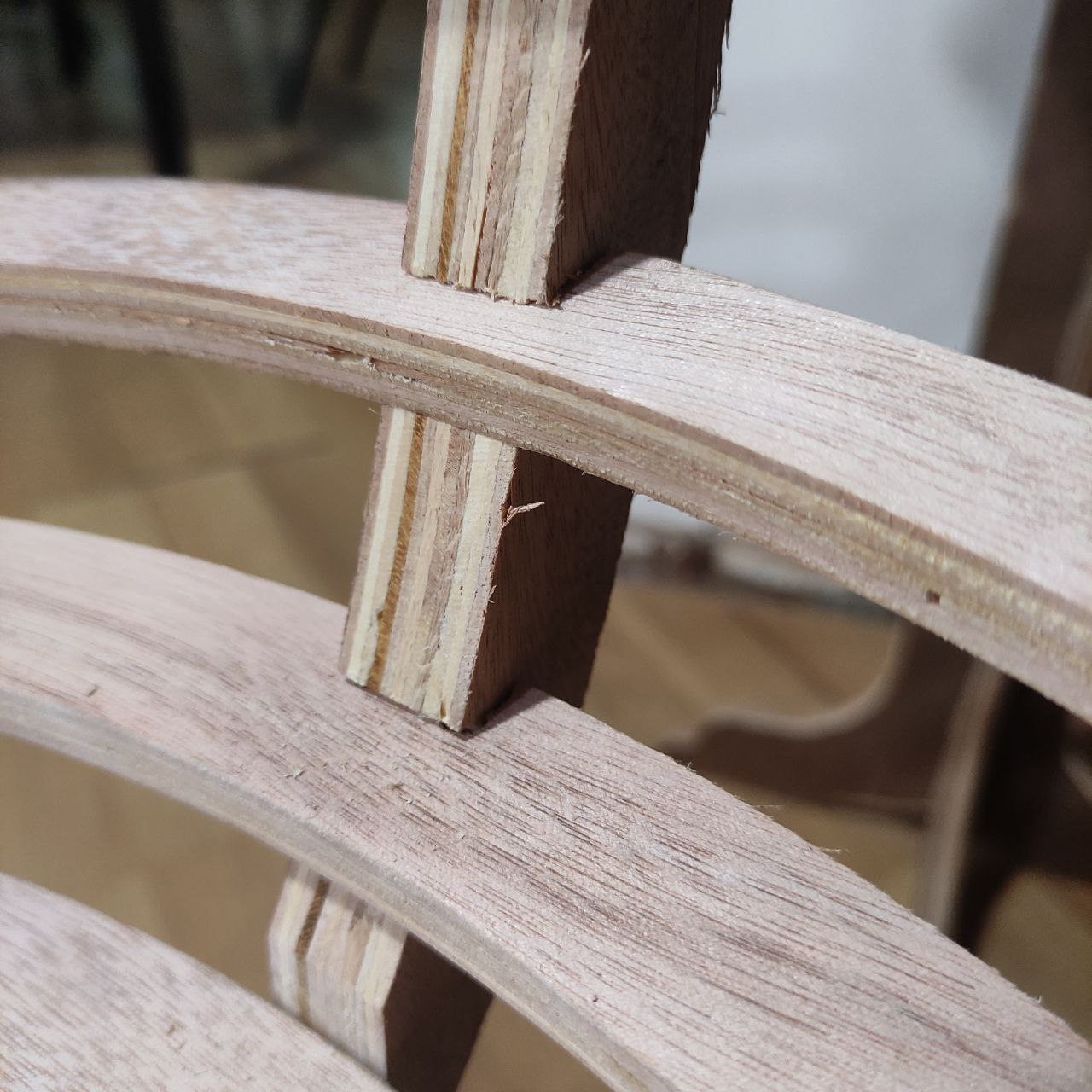
- the joints are correctly fitted
Hero Shot
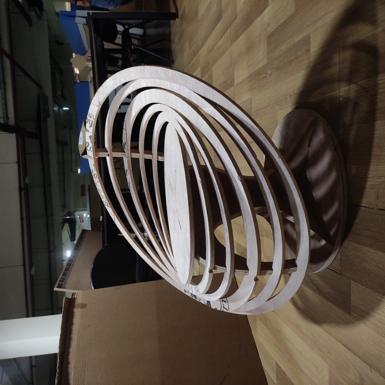
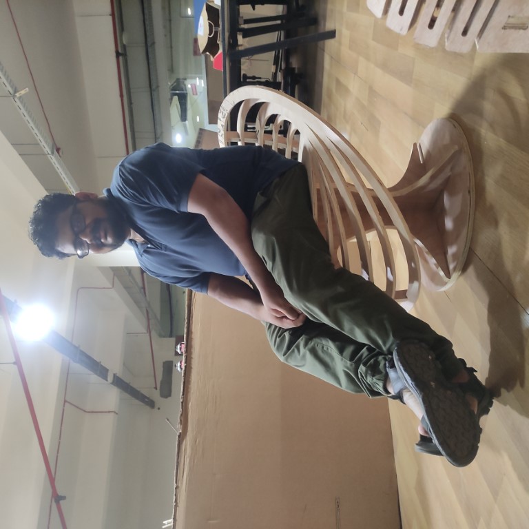
our instructor Jojin on the chair, from his expression we can see that he is very comfortable,
Hence we can conclude that this project is a success
Design files:
dxf file for laser cutting:
.crv file for CNC machining: