
Embedded Programming
WEEK - 4
Objective
- To compare the performance and development workflows for other architectures
- To read the datasheet for our micro-controller
- To use our programmer to program your board to do something
CONTENTS
Reading the datasheet
I have chosen to examine the datasheet for the ESP32 microcontroller.
The datasheet of our ESP32
The ESP32 datasheet contains information about the microcontroller's features and capabilities, like pinouts, electrical characteristics, memory organization, peripheral interfaces, and communication protocols. It is an essential resource if you are going to work with the ESP32.
Here I learned different parameters and functions of different ports from this datasheet
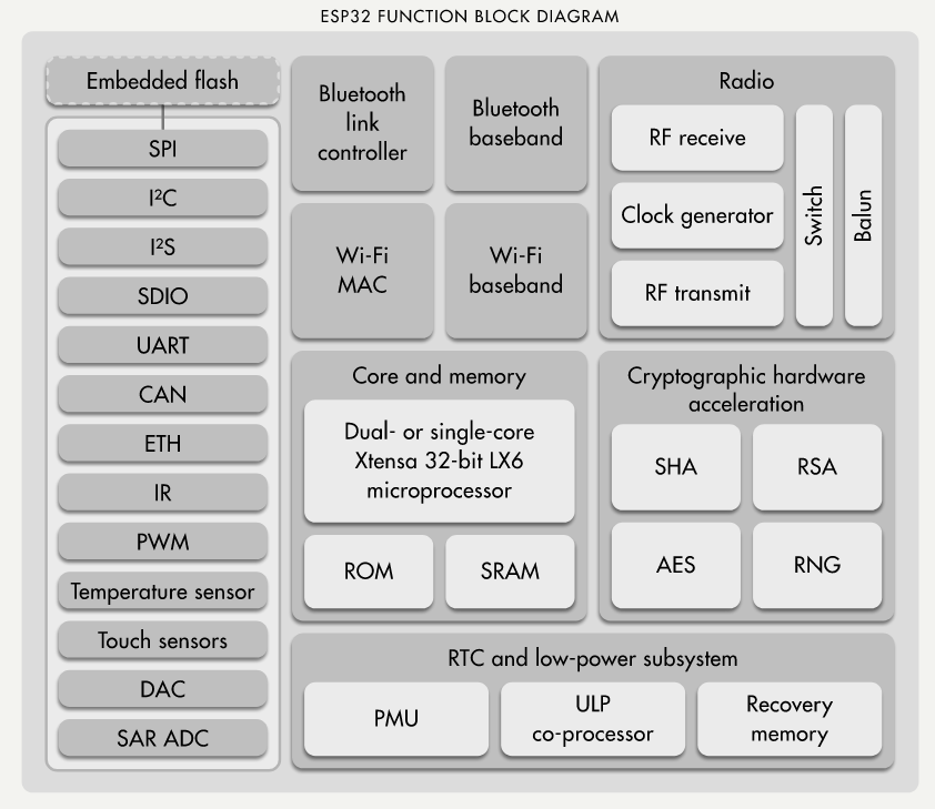
- This is the block diagram of ESP32, from this, we can easily identify its capabilities.
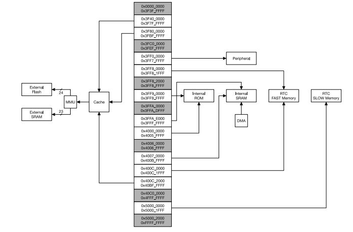
flow diagram
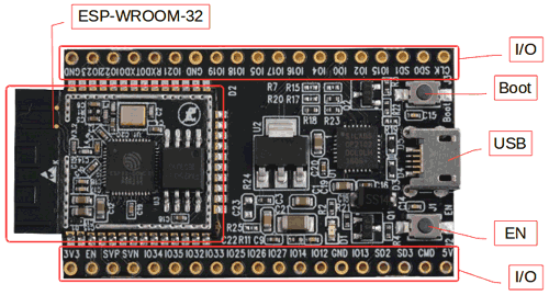
ESP32
ESP-WROOM-32
- The development board I got was ESP32
- and I was told to program it using Arduino IDE
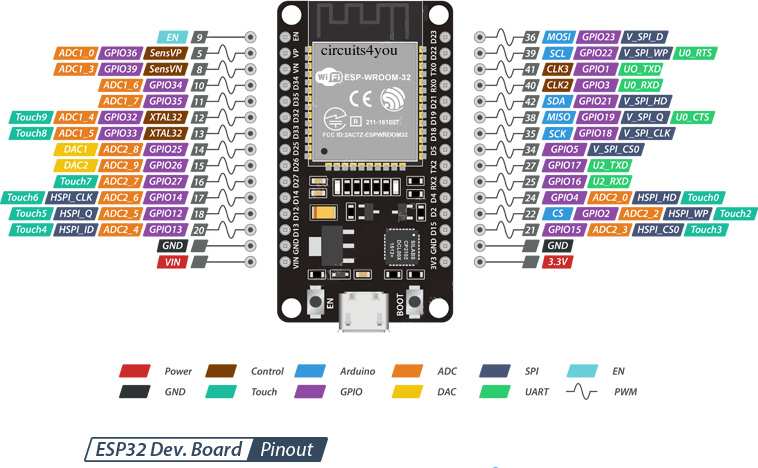
3.3V micro-controller ESP32.
| ESP32 | |
|---|---|
| Specification | Value |
| Number of cores | 2 |
| Architecture | 32 bit |
| CPU Frequency | |
| Wi-Fi | YES |
| Bluetooth | YES |
| RAM | 512 KB |
| FLASH | 16 MB |
| GPIO Pins | 36 |
| Communication Protocols | SPI, IIC, I2S, UART, CAN |
| ADC channels | 18 channels |
| ADC Resolution | 12-bit |
| DAC channels | 2 |
| DAC Resolution | 8-bit |
Trying Arduino for the first time
Arduino IDE Programming <>
The Arduino programming language is a modified version of C/C++ Usually, we program in C++ with the addition of methods and functions. A program written in Arduino programming language is called Sketch and saved with .ino extension. You can even use Python to write an Arduino program. All these languages are text-based programming languages.
- I installed Arduino IDP into my computer, you can download it from here
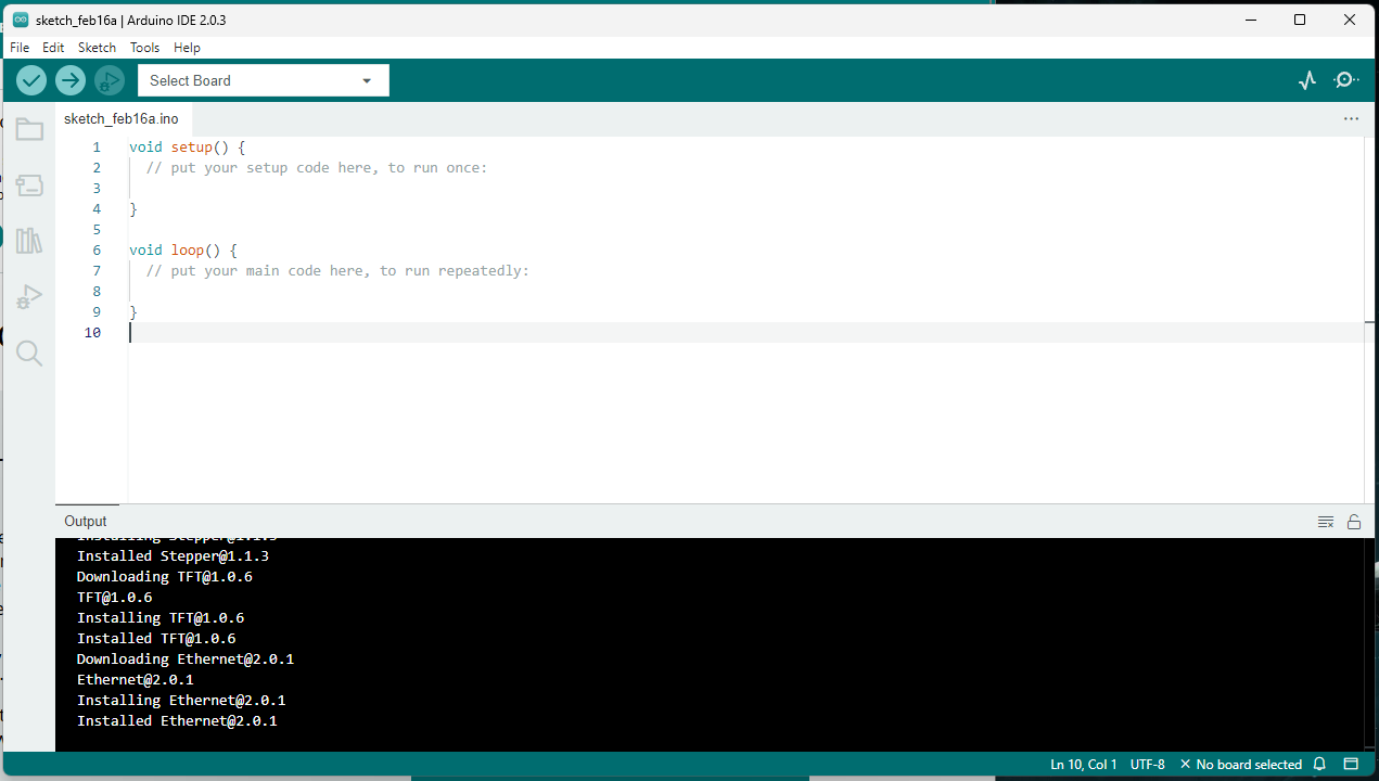
*when you first open it it will look like this
- now the board I got was not in this program, so i had to add it manually
Installing ESP32 Add-on in Arduino IDE
to add ESP32 Board to your Arduino - here’s the tutorial-
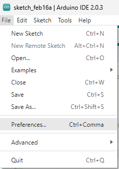
- Open your Arduino IDE, go to File>Preferences
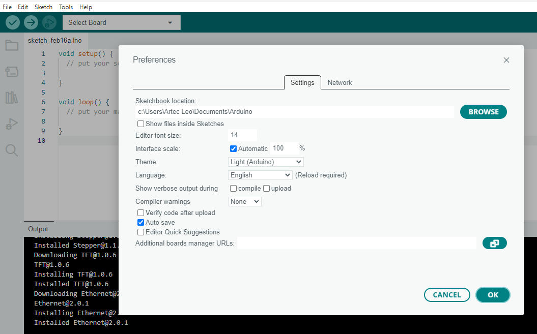
- put this https://dl.espressif.com/dl/package_esp32_index.json link here at the additional board's manager URLs

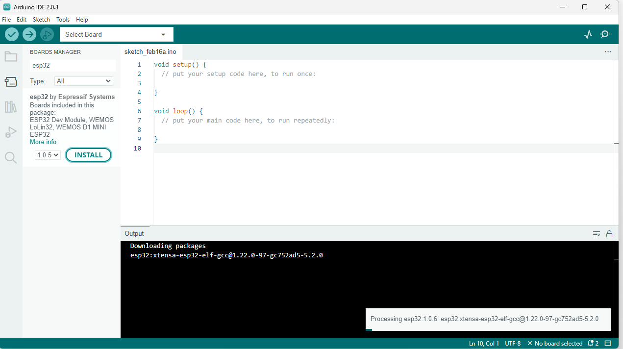
- installing
Now testing the ESP32 Board
- Open the Arduino IDE and plug the ESP32 Board into your computer.
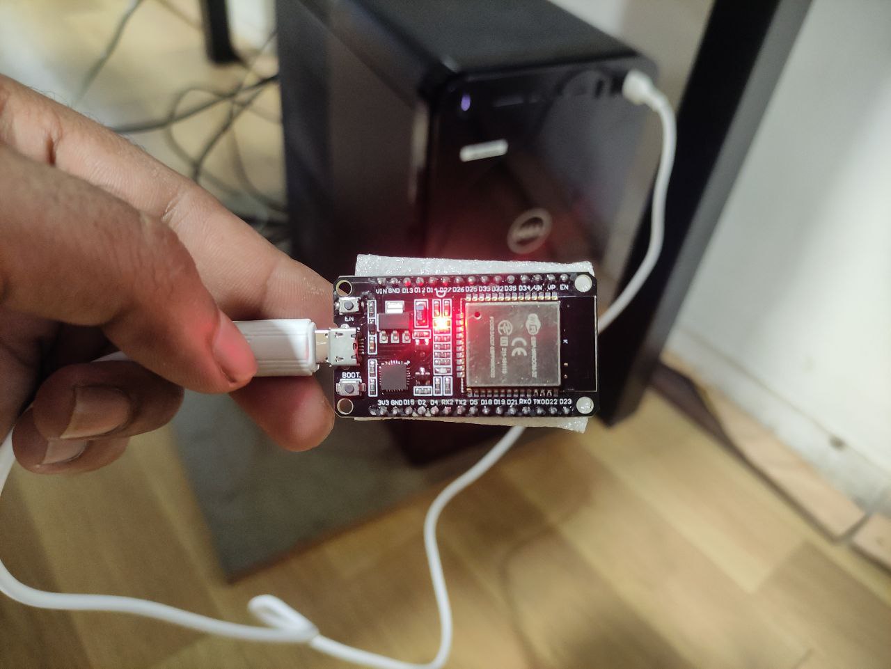
*ESP32 connected to my computer
- now select the board in Tools> Board menu "DOIT ESP32 DEVKIT V1"
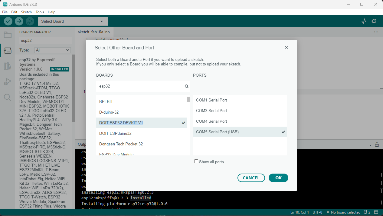
The one I am having is the Esp32 DevKit v1, which is one of the development boards created to evaluate the ESP-WROOM-32 module
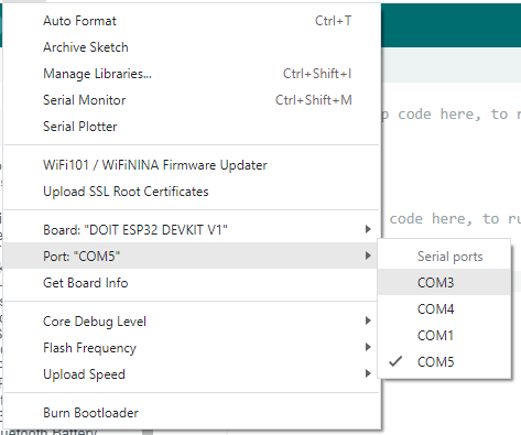
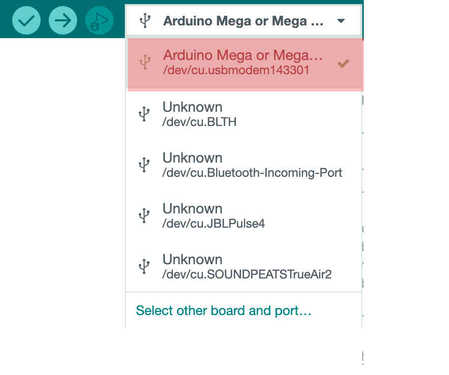
- Now I have to select a post, for that go to Tools > Port >
* for me, it was “COM15”
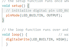
- Now the board is connected, I tried blinking the build-in blue LED
- for that, I used the code that was in the library as examples
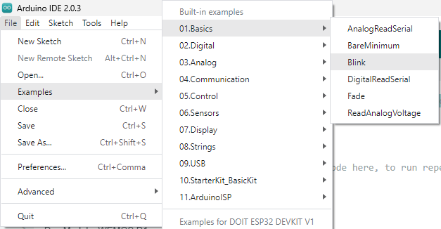
*follow these steps 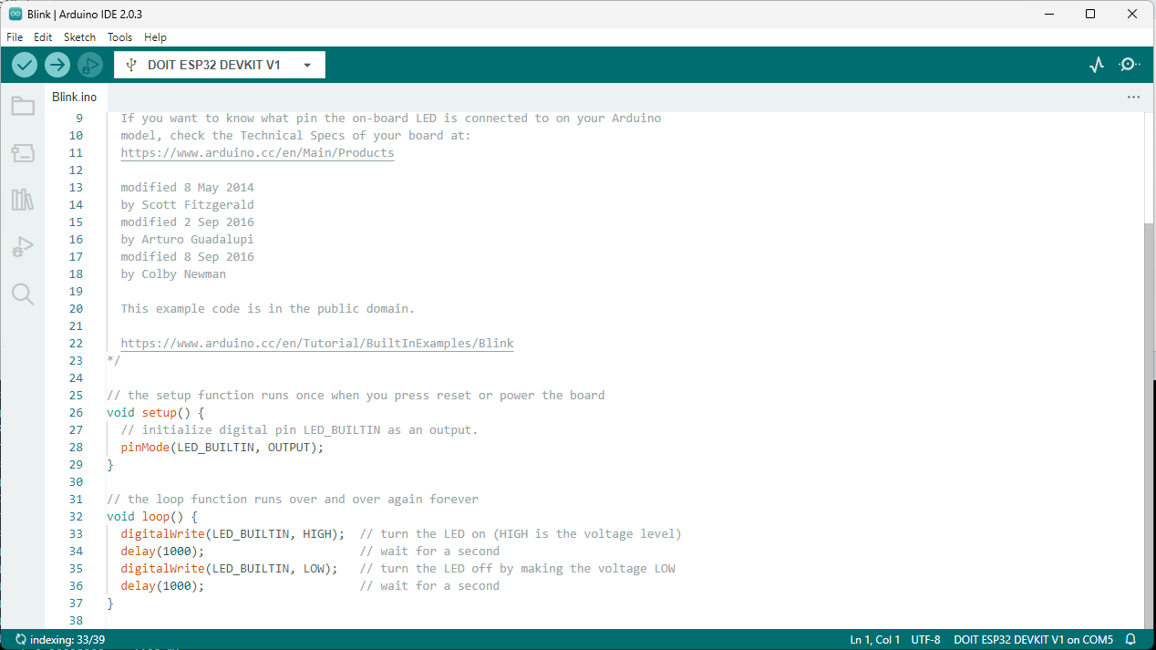
*When the example is opened, it will be like this
void setup() {

pinMode(LED_BUILTIN, OUTPUT);

}

void loop() {

digitalWrite(LED_BUILTIN, HIGH);

delay(2000);

digitalWrite(LED_BUILTIN, LOW);

delay(2000);

}
While coding use Pinmode(13, OUTPUT); if you know which pin is the led or use LED_BUILTIN
- delay(1000); is the delay between the blinks which is “1000 ms” that is one second
blinking in 1000ms delay
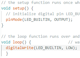
- now changing blinking time to 100ms, so it will be blinking faster
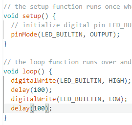
- now just turning into and on position
Trying to connect OLED to my ESP32
For a detailed tutorial click here
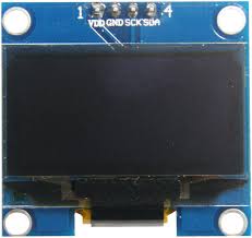
OLED Display Module
this is a 1.2-inch I2C OLED display →
a powerful single-chip CMOS OLED driver controller – SSD1306,
so only a little work from my ESP-32
Wiring of an OLED display module to ESP32
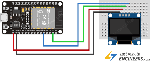
- start by connecting the VCC pin to the ESP32’s 3.3V output and the GND pin to the ground.
- now connect the SCL and SDA pins to the ESP32’s I2C pins D22 and D21, respectively.
Now we have to Install some Libraries
Adafruit SSD1306 library is written to hide the complexities of the SSD1306 controller, allowing us to control the display with simple commands.
- navigate to Sketch> Include Library> Manage Libraries
- search for adafruit ssd1306 and install it
- To display graphics primitives such as points, lines, circles, and rectangles, it must be paired with the Adafruit GFX Library Install this library as well.
- Adafruit SSD1306 library uses Adafruit Bus IO Library- So, look for Adafruit BusIO in the library manager and install it as well.
Now the Code for ESP32- for displaying text
- displaying a simple text, in white and inverted text.
#include <SPI.h>
#include <Wire.h>
#include <Adafruit_GFX.h>
#include <Adafruit_SSD1306.h>

#define SCREEN_WIDTH 128 // OLED display width, in pixels
#define SCREEN_HEIGHT 64 // OLED display height, in pixels

// Declaration for SSD1306 display connected using I2C
#define OLED_RESET     -1 // Reset pin
#define SCREEN_ADDRESS 0x3C
Adafruit_SSD1306 display(SCREEN_WIDTH, SCREEN_HEIGHT, &Wire, OLED_RESET);

void setup()
{
  Serial.begin(9600);
  // initialize the OLED object
  if(!display.begin(SSD1306_SWITCHCAPVCC, SCREEN_ADDRESS)) {
    Serial.println(F("SSD1306 allocation failed"));
    for(;;); // Don't proceed, loop forever
  }
  // Clear the buffer.
  display.clearDisplay();
  // Display Text
  display.setTextSize(2);
  display.setTextColor(WHITE);
  display.setCursor(0,30);
  display.println("Hi Mufeed");
  display.display();
  delay(2000);
  display.clearDisplay();
  // Display Inverted Text
  display.setTextColor(BLACK, WHITE); // 'inverted' text
  display.setCursor(0,30);
  display.println("ESP32 here!");
  display.display();
  delay(2000);
  display.clearDisplay();
}
void loop() {
}
Like these numbers, symbols, and scrolling text can also be displayed.
Programming on Arduino Mega 2560
Next, I tried Fading LED lights on an Arduino Mega 2560 board.
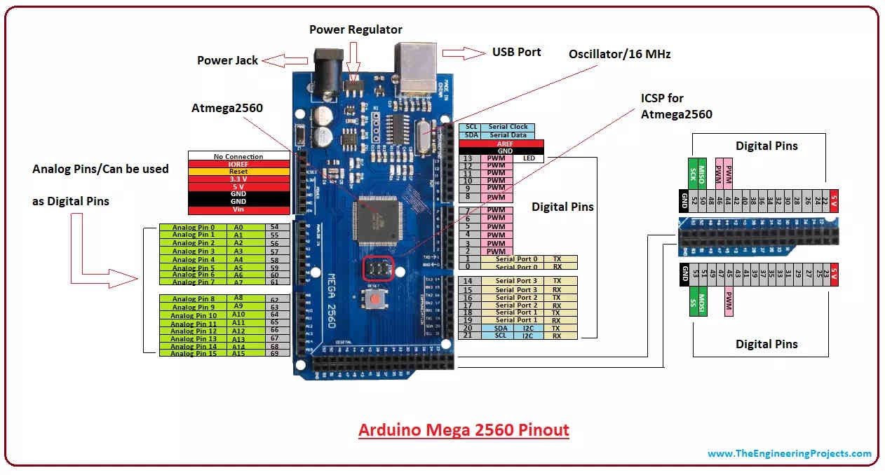
- I started with a fading example from the library.
- now select the Arduino Mega board
- Make changes to the code according to the board arrangements. I have connected LEDs from pins 2 to 8.
int ledPin;
void setup() {
}
void loop() {
for (tedPin= 2; ledPin < 8; tedPin++) {
for (int fadeValue 0; fadeValue 255; fadeValue += 5)}
analogWrite( ledPin, fadeVaIue) ;
delay(100);
}
for (int fadeVaIue = 255; fadeVaIue>= O; fadeValue -= 5)}
analogWrite( ledPin, fadeValue) ;
delay( 100);
}
}
}- the result is this 👇🏼
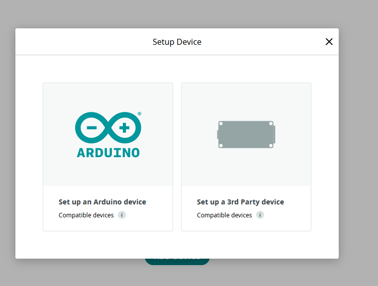
Arduino IoT cloud
- adding the device
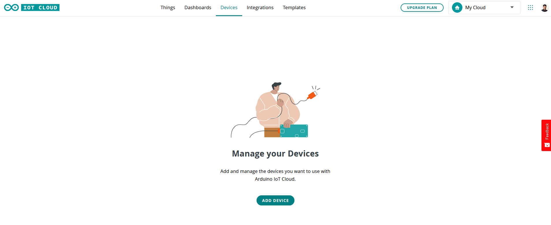
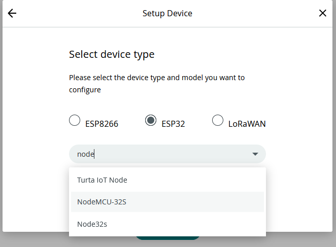
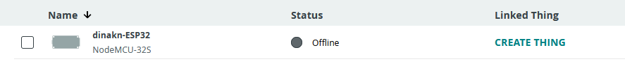
- my device is added as dinkan-ESp32
- adding a network
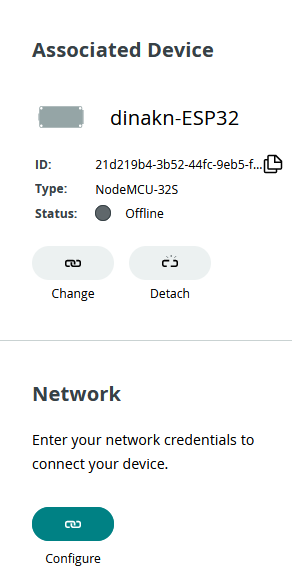
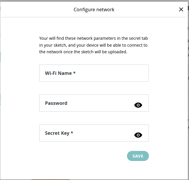
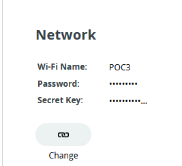
- save the DEVICE ID and SECRET KEY
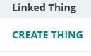
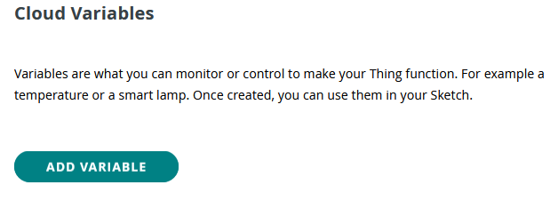
- now we have to create a thing
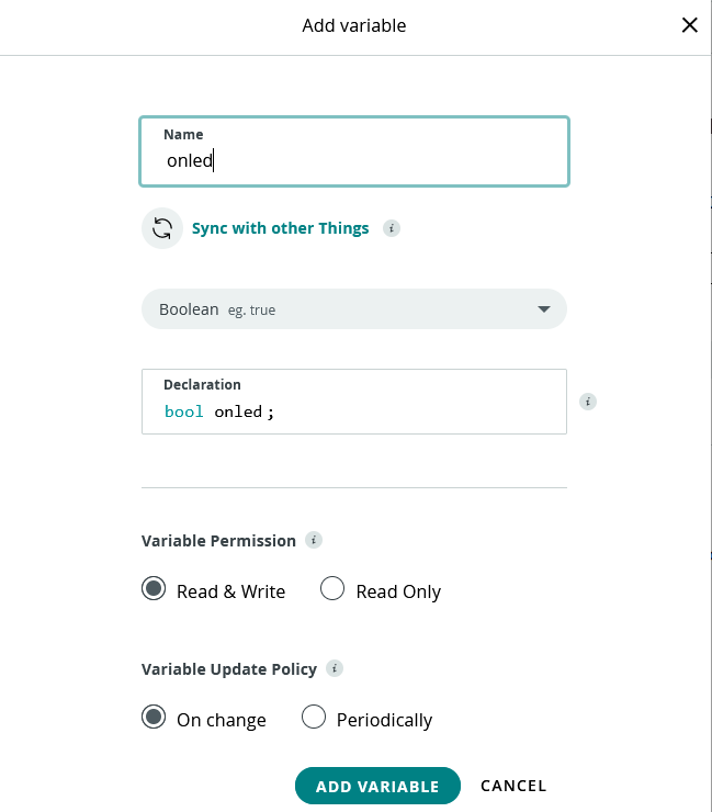
- now add a variable, for turning on the led here “onled”
- now add the code in the “sketch” tab
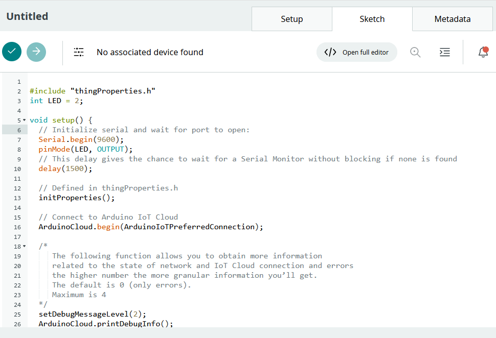
#include "thingProperties.h"
int LED = 2;

void setup() {
  // Initialize serial and wait for port to open:
  Serial.begin(9600);
  pinMode(LED, OUTPUT);
  // This delay gives the chance to wait for a Serial Monitor without blocking if none is found
  delay(1500);

  // Defined in thingProperties.h
  initProperties();

  // Connect to Arduino IoT Cloud
  ArduinoCloud.begin(ArduinoIoTPreferredConnection);

  /*
     The following function allows you to obtain more information
     related to the state of network and IoT Cloud connection and errors
     the higher number the more granular information you’ll get.
     The default is 0 (only errors).
     Maximum is 4
  */
  setDebugMessageLevel(2);
  ArduinoCloud.printDebugInfo();
}

void loop() {
  ArduinoCloud.update();

  chart = random(0, 500);
  Serial.println("chart =" + String(chart));
  delay(500);

}


/*
  Since Led is READ_WRITE variable, onLedChange() is
  executed every time a new value is received from IoT Cloud.
*/
void onLedChange()  {
  Serial.println("led=" + String(led));
  if (led) {
    digitalWrite(LED, HIGH);
    Serial.println("High");
  }

  else {
    digitalWrite(LED, LOW);
    Serial.println("Low");
  }
}

/*
  Since Chart is READ_WRITE variable, onChartChange() is
  executed every time a new value is received from IoT Cloud.
*/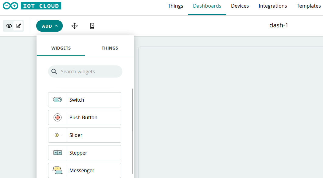
void onChartChange() {- add the dashboard, here i made a dashboard as ”dash-1”
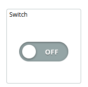
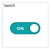
- no add a switch
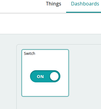
- link a variable to that switch
- here the variable “onled” is linked
- uploading code to ESP32
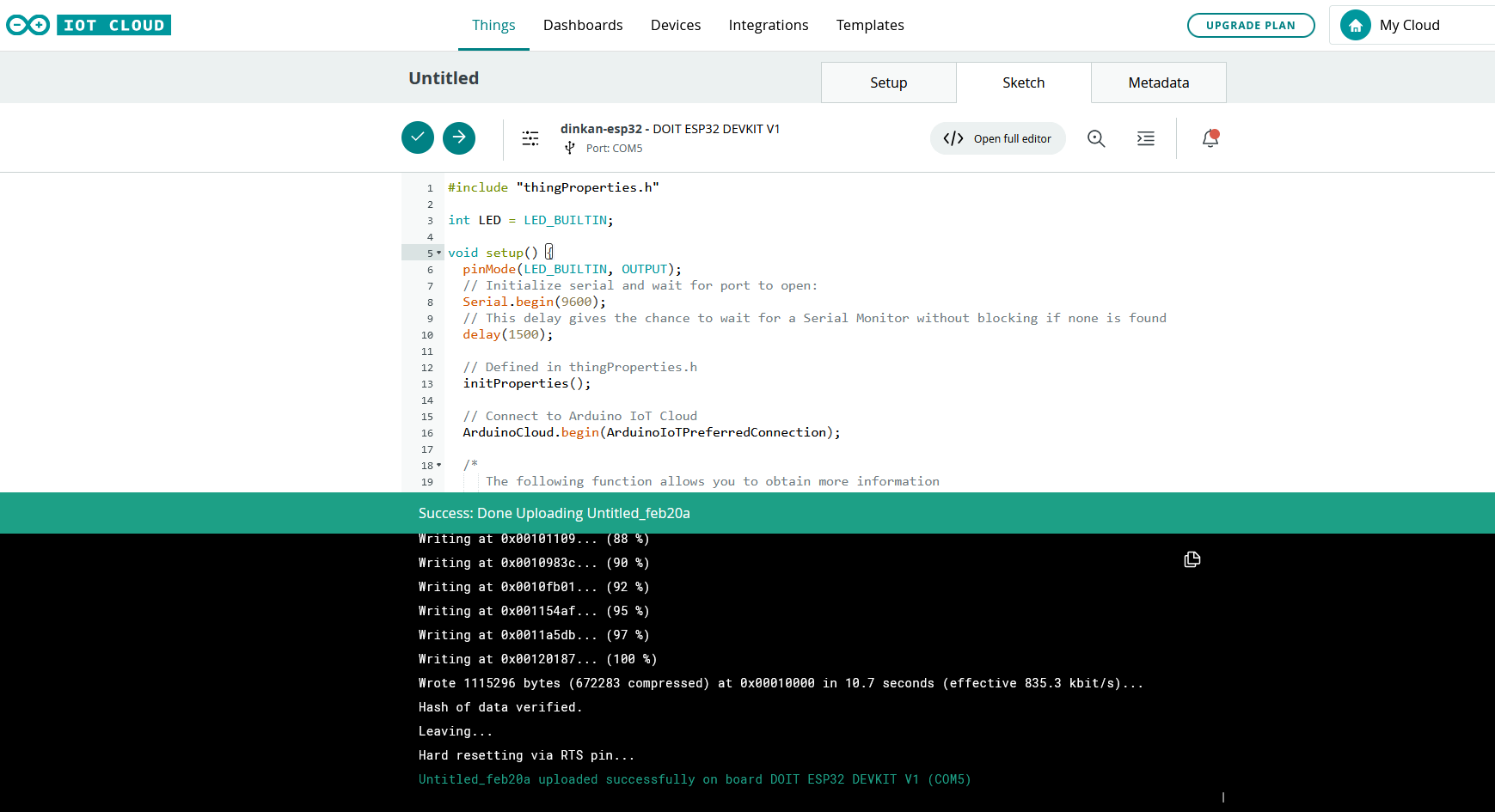
- now the LED turns on and off when the switch is pressed
.jpg)
.jpg)
- Vola, my board can now be controlled through the IOT cloud.
Resources and Downloads
- sketch for led blinking:
- sketch for Old display:
- Arduino IOT sketch for esp32