
Input Devices
WEEK-11
CONTENTS
Objective
👉 Group assignment: (Click here to go to Group assignment page)
- Probe an input device's analog levels and digital signals
👉 Individual assignment:
- Measure something: add a sensor to a micro controller board that you have designed and read it.
- In this week our main task is to learn how to interface a sensor and read data from it. I wanted to try to learn how to use the Ultrasonic sensor as I'm planning on using it for my final project.
This week was difficult for me as I'm from a mechanical background. I was lost in the beginning thinking about what I can do. Its not the sensors I'm having difficulty with- I understand how they work- but Its how they need to be programmed, where I'm stuck at.
For this week I'm going to be relying on Arduino code
The working of ADC
Most sensors respond to the changes in physical properties in a continuous manner, which produces an analog signal. So in order for the micro controller to understand what is happening we need to convert these continuous signals into discrete ones. Hence the function of an ADC.
In brief, what an ADC does is that it samples data at certain intervals so that you can convert a continuously varying signal into a set of discrete values. It uses either an 8 bit or a 10 bit counter to store the values. 8 bit gives you 2^8 bits of storage (256 bits) and 10 bit gives you 2^10 bits of storage (1024 bits)
Designing the board
This week I’m am using AT SAMD 11 C 14A microcontroller,
AT SAMD 11 C 14A
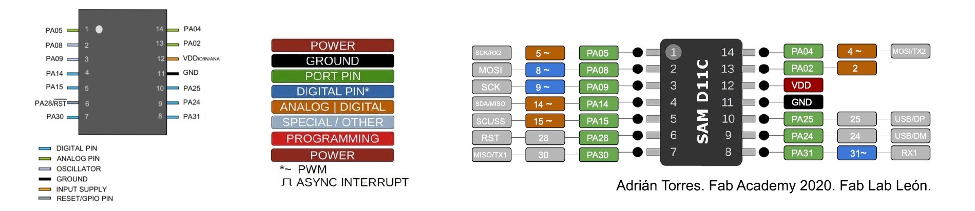
- VDD: Supply voltage.
- GND: Ground.
- Digital pins: PA02, PA04, PA05, PA08, PA09, PA14, PA15, PA31.
- USB pins: PA24, PA25.
- Analog pins: PA02, PA04, PA05, PA14, PA15.
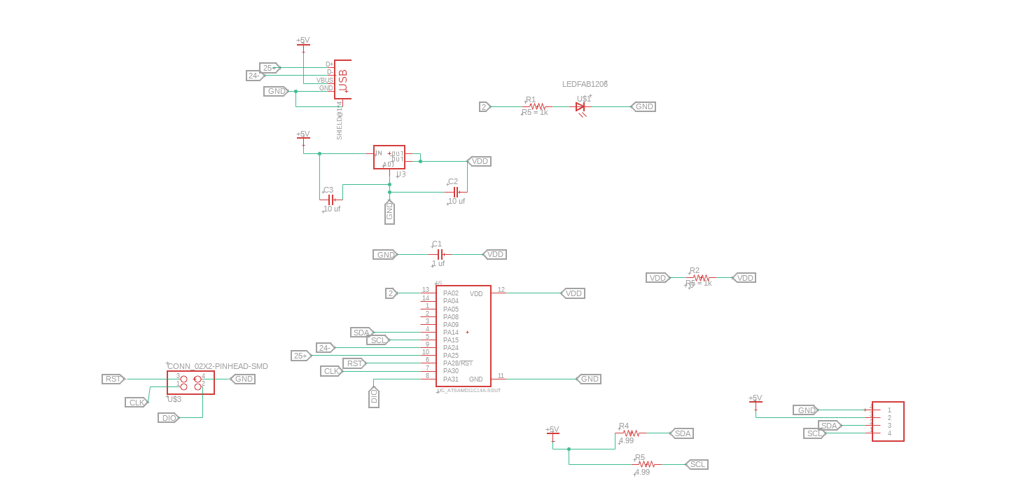
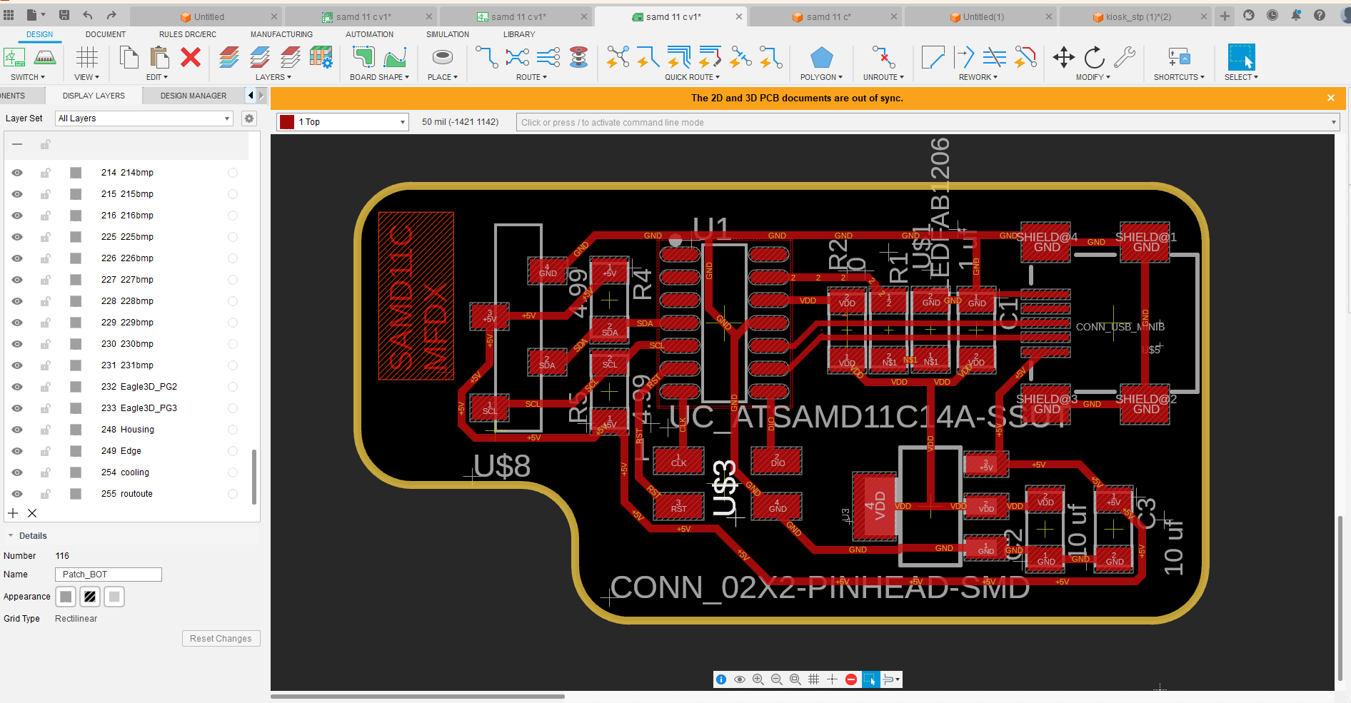
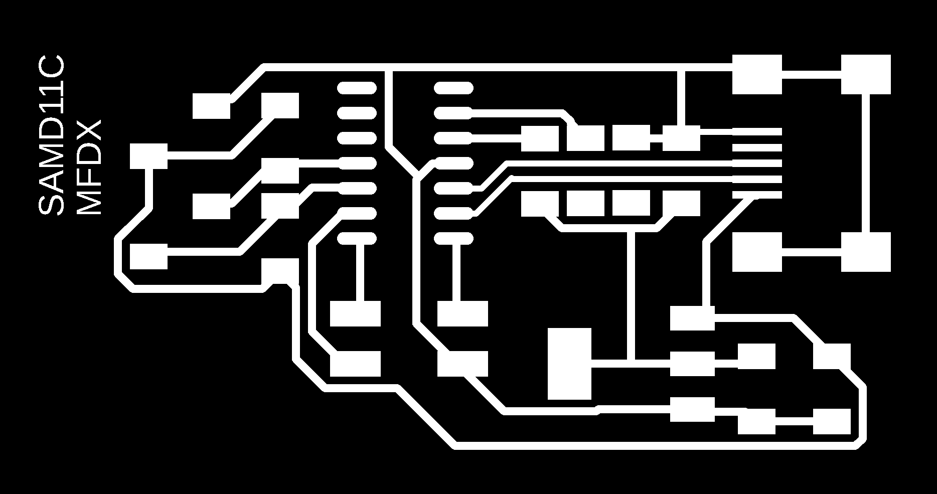
Design in fusion 360
schematic
board
selecting components
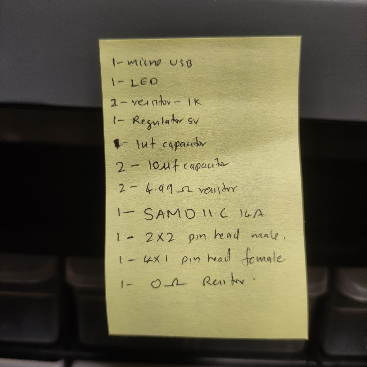
these where the components needed for the board
| quantity | component |
|---|---|
| 1 | AT SAMD 11 C 14A |
| 1 | mini USB |
| 1 | LED |
| 2 | 1K resistor |
| 1 | regulator 5v |
| 1 | 1uF capacitor |
| 2 | 10uF capacitor |
| 2 | 4.99 ohm resistor |
| 1 | 2x2 pinhead male |
| 1 | 4x1 pinhead female |
| 1 | 0 ohm resistor |
- BOM of PCB
milling the board


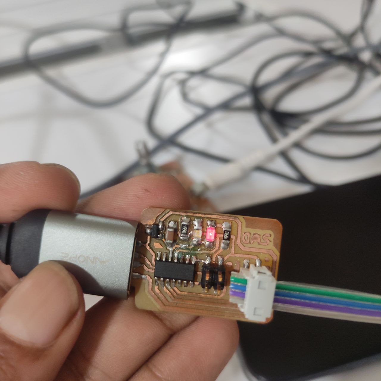
the board after milling

after soldering all the components
Programming the board with SDI programmer
programming the board
the sdi programmer
- now the board is ready for use
programming the new SAMD 11 C board
- first we have to install the Fab SAM core library in Arduino IDEQuentin Bolsee / Arduino SAM Tutorial · GitLabCBA
 https://gitlab.cba.mit.edu/quentinbolsee/Arduino-SAM-tutorial/
follow these steps to install 👆🏼
- after installing these we can select our board
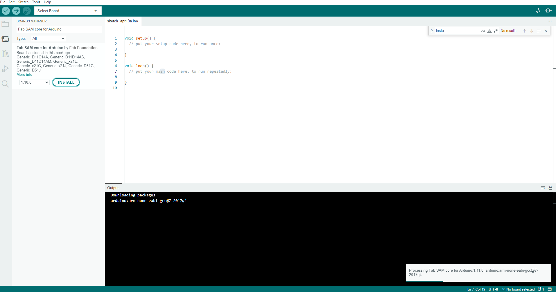
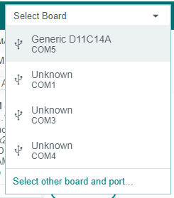
- select the board an run a sample code to blink
the led has blinked- the board is working now,
—- —- —- SUCCESS IN BUILDING A NEW BOARD WITH SAMD 11— —- —— —-
Testing the input devices
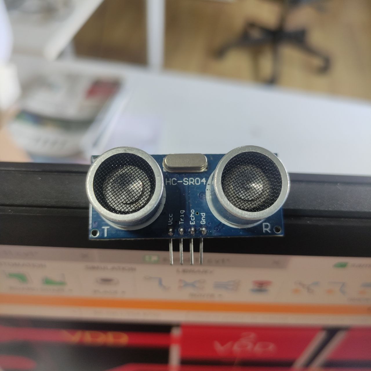
Ultra sonic sensor
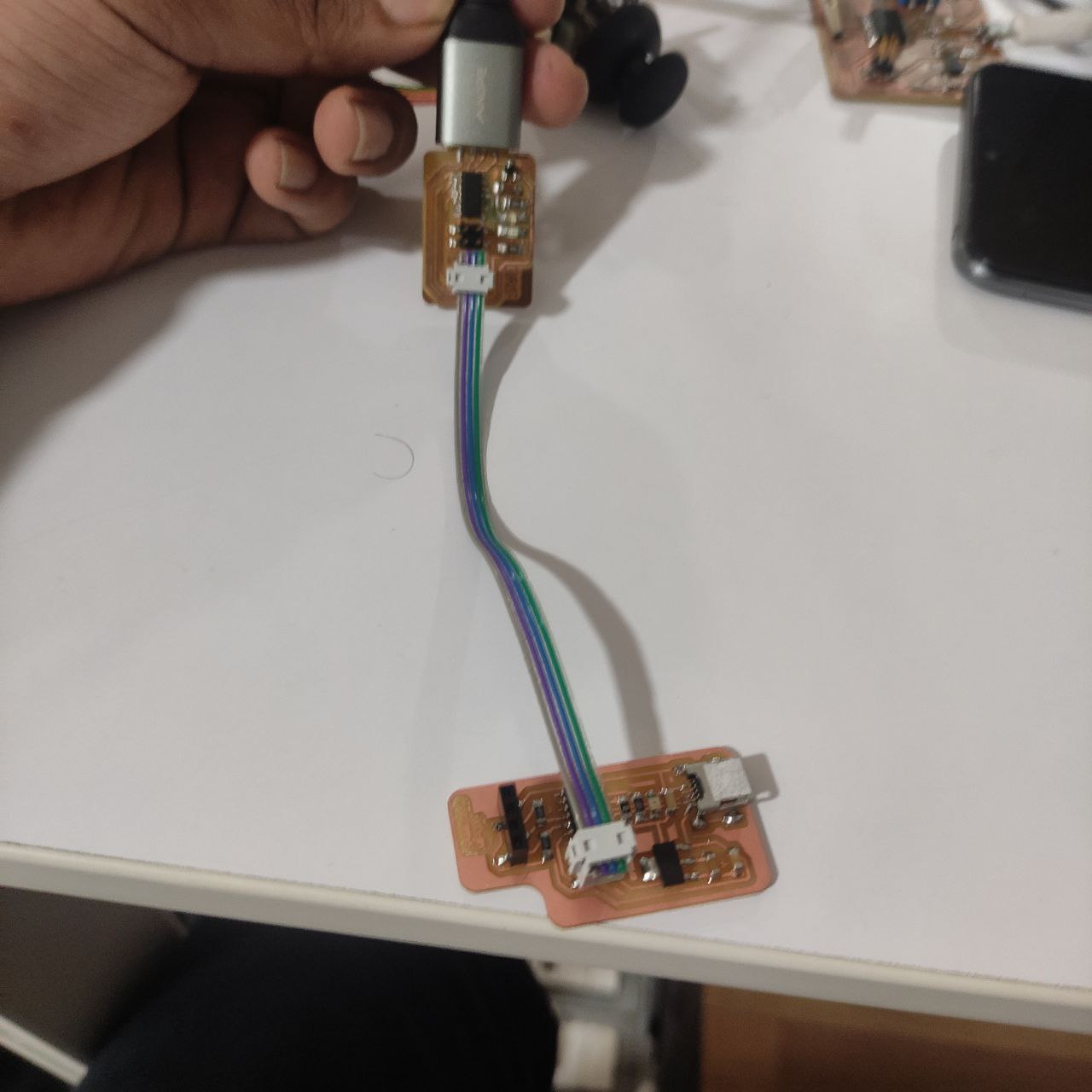
- Connection and schematic
In this case we only need four cables; one for VCC to 5V, one for GND, another cable for the Trigger (PA15), and another for the Echo (PA31).
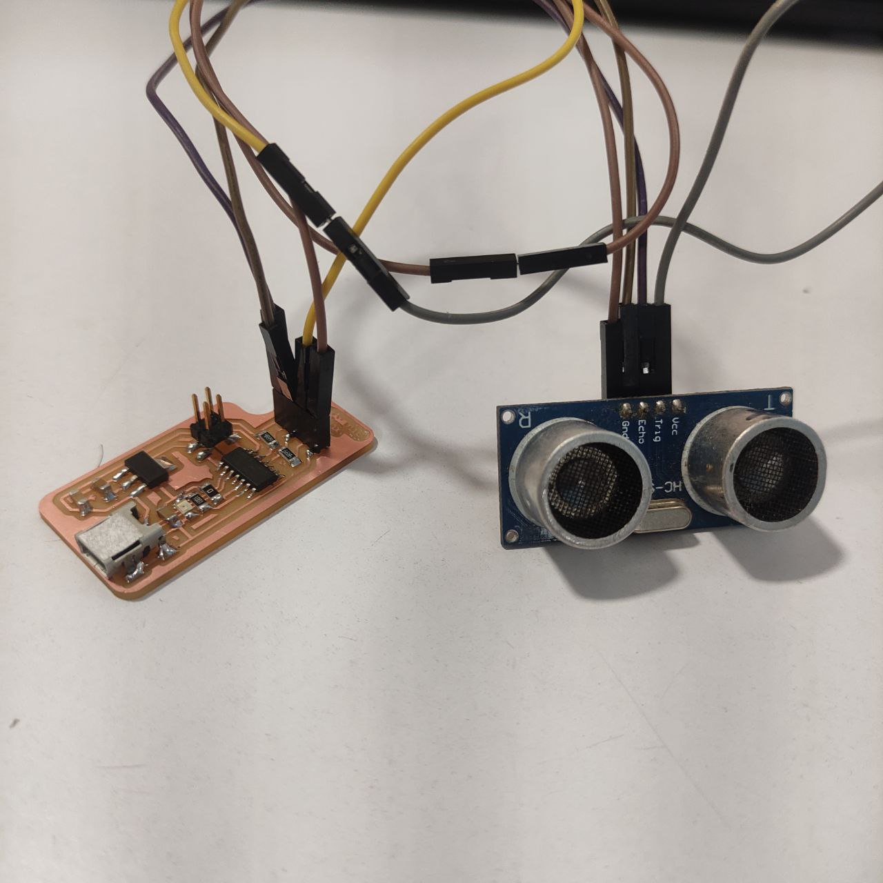
this is the connection
programming
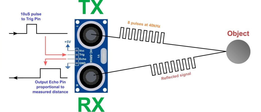
- programming to use a digital sensor such as the Ultrasonic sensor.
Run this code in Arduino IDE 👇🏼
//Fab Academy 2023 - Fab Lab kochi- ufeed mohmd
//Ultrasonic sensor
//SAMD11C


const int EchoPin = 14;
const int TriggerPin = 15;

void setup() {
   Serial.begin(115200);
   pinMode(TriggerPin, OUTPUT);
   pinMode(EchoPin, INPUT);
}

void loop() {
   int cm = ping(TriggerPin, EchoPin);
  Serial.print("");
   Serial.println(cm);
   delay(1000);
}

int ping(int TriggerPin, int EchoPin) {
   long duration, distanceCm;

   digitalWrite(TriggerPin, LOW);  //to generate a clean pulse we set LOW 4us
   delayMicroseconds(4);
   digitalWrite(TriggerPin, HIGH);  //we generate Trigger (trigger) of 10us
   delayMicroseconds(10);
   digitalWrite(TriggerPin, LOW);

   duration = pulseIn(EchoPin, HIGH);  //we measure the time between pulses, in microseconds

   distanceCm = duration * 10 / 292/ 2;   //we convert distance, in cm
   return distanceCm;
}
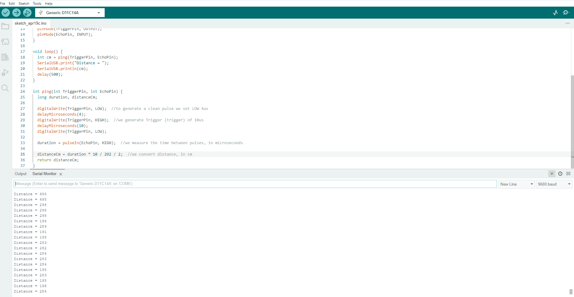
—> We can see the change in distance, in serial monitor
measuring the distance
- here i used a measuring tape in the background to verify that the measurements shown in the serial monitor is correct.
Design files
- Schematic and PCB designs: