Mechanical design & machine design
WEEK- 10
For Group assignment click here
Here I will only be sharing my part of the whole project.
SCA-KAI
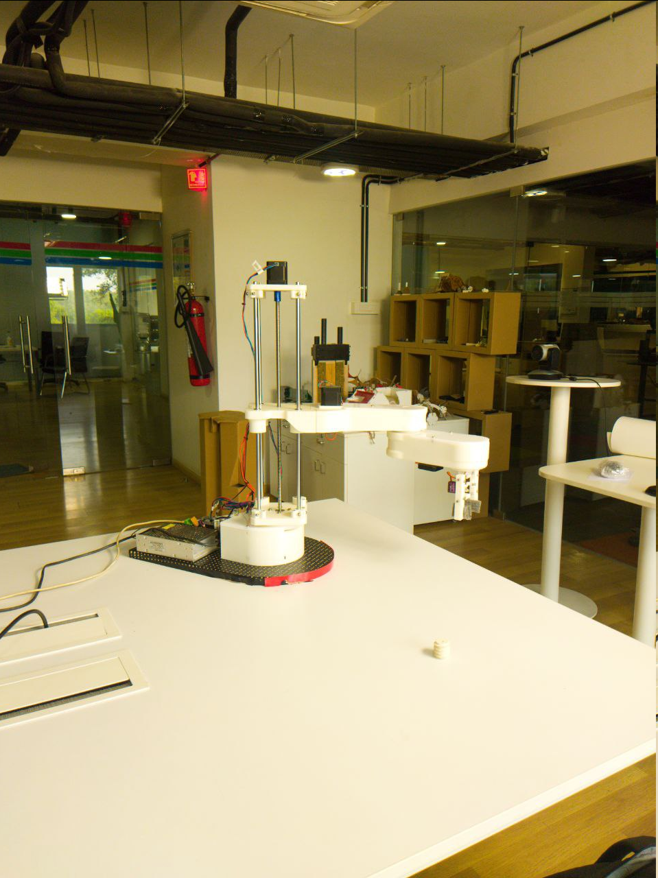
The beginning
- initial concept sketch, the concept idea was to create a scara-type robot and place it on a Trax, so that it can move and pick and place things also used for different movement purposes
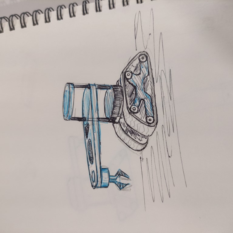
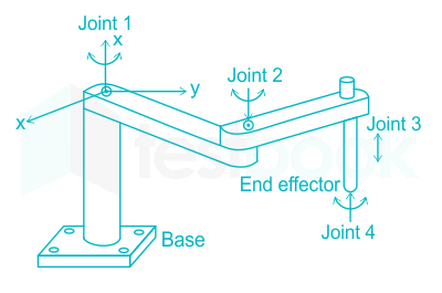
the initial idea was to create a robot based on the SCARA ( Selective Compliance Articulated Robot Arm) platform
My contributions
Initially, there were officially assigned tasks for everyone in this project, but when we started the project had equal contributions in most of the work, so we had to help each other.
And mentioned below are the areas where I worked the most and the certain areas where I took the lead.
- Naming the project
since we are making our own version of SCARA, we had to name it something we can relate to.
we brainstormed some names and came to a conclusion to name it SCA-KAI
where SCA stands for “ Selective Compliance Articulated robot “ and “KAI” for the work “kayyi” which means arm in Malayalam.
hence the name SCA-KAI.
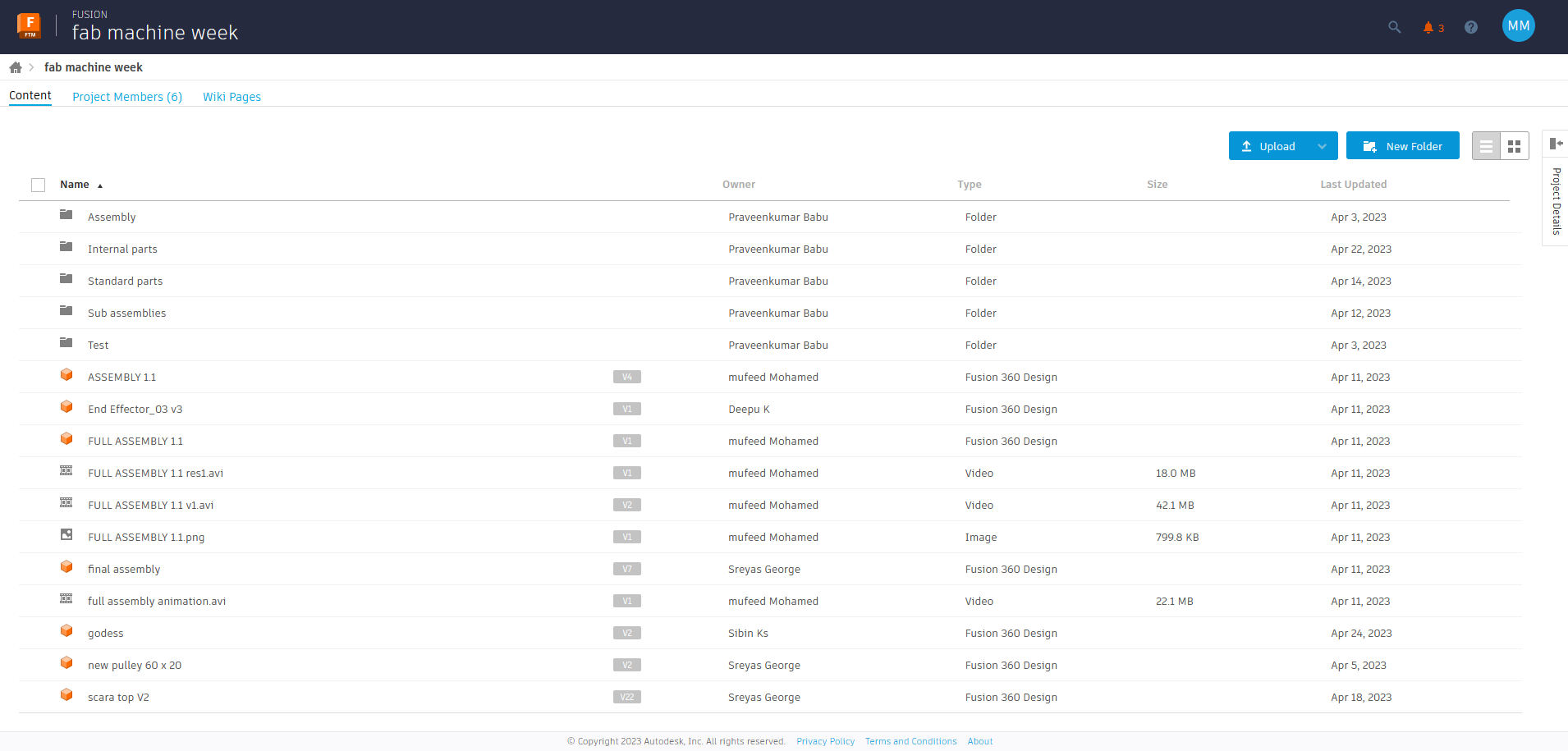
CAD Designing - Collaborative design in Fusion 360
we had set up the Collaborative design in Fusion 360, Which allows multiple people to work on the same design project simultaneously in real-time, since we had 5 people working on the same project it was necessary
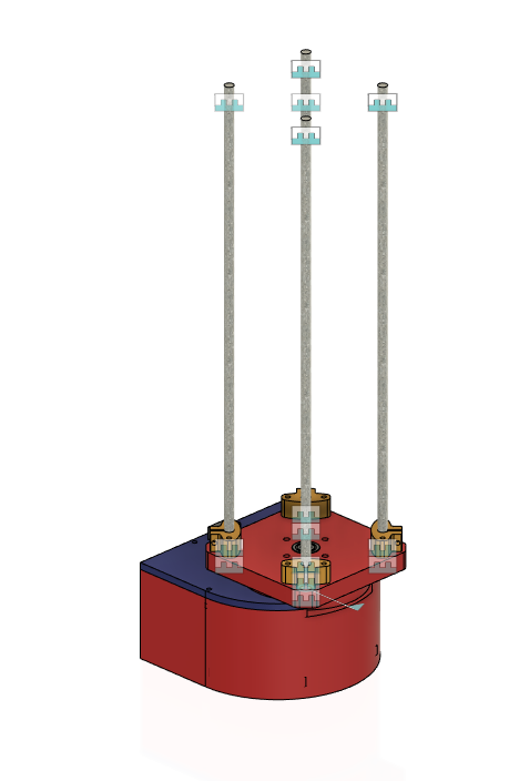
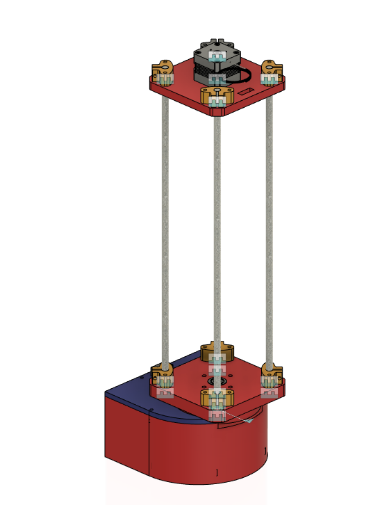
Designing the two arms
parallel to this the design of the base and z-axis was almost completed by Deepu and Sreyas
so I got some references for designing the arm from their design.
- initial hand sketch of the arm
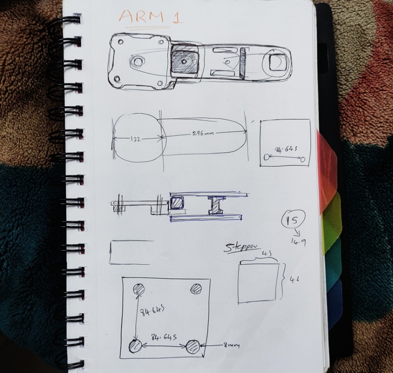
- since there are pulleys and stepper motors as drive
- we had to do some simple calculations to find the length between the pulleys
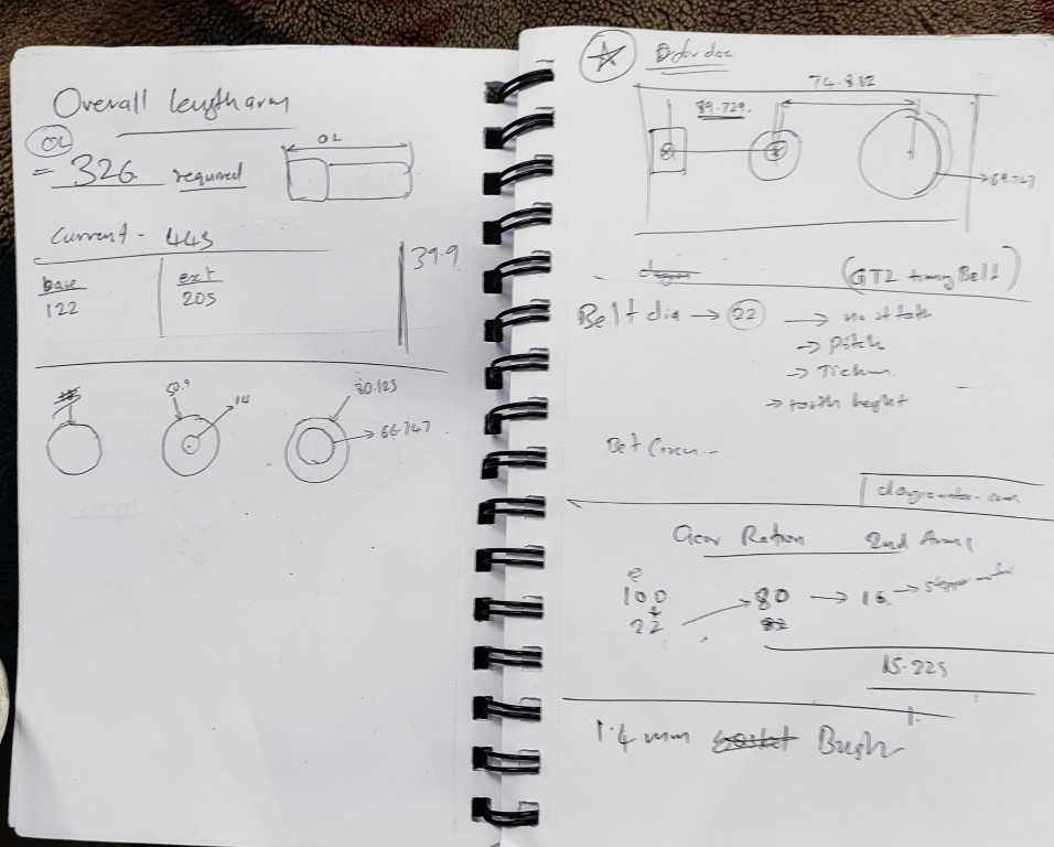
- The calculations
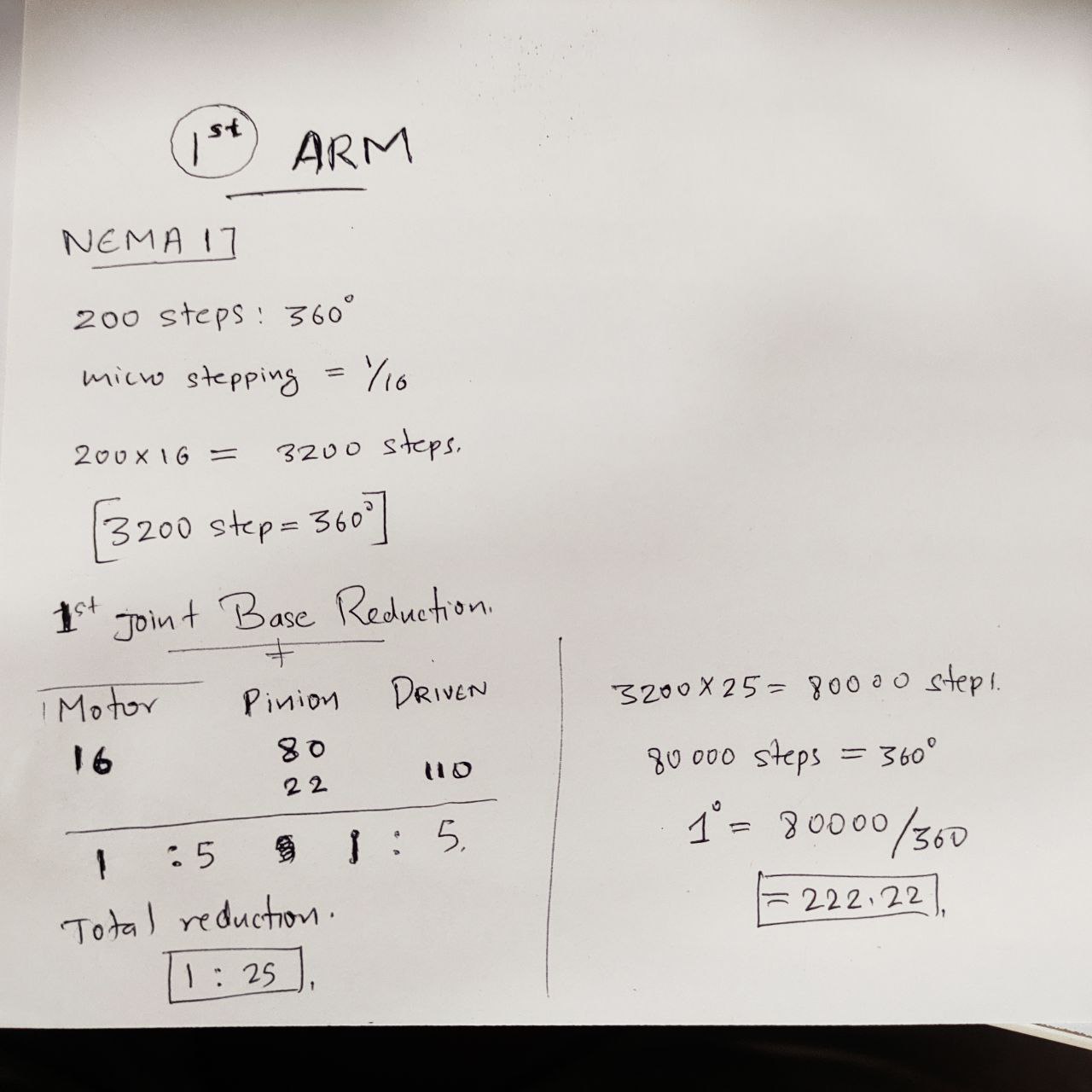
great ratios
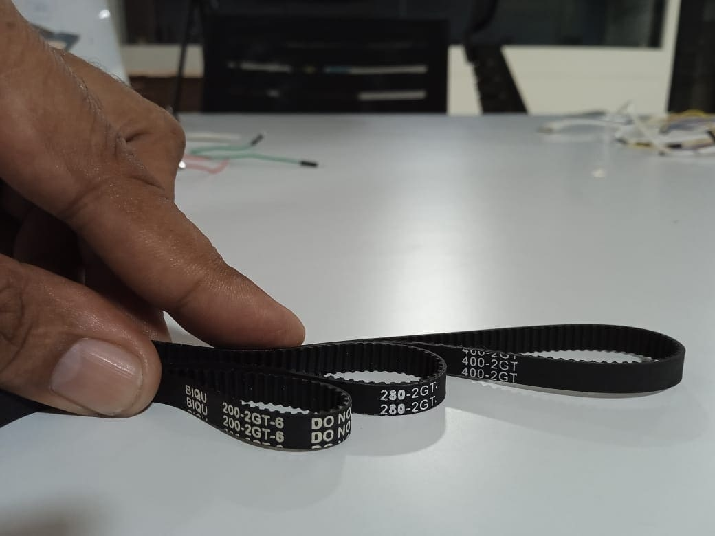
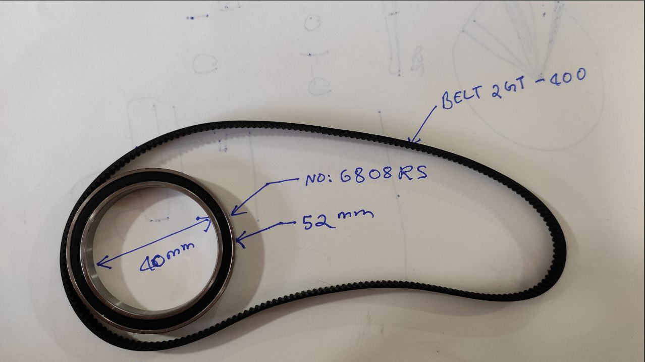
here we are using a GT2 timing belt,
no of teeth= 200
pitch= 1mm
thickness= .75 +0.63 mm
tooth height= 0.75
we also used this calculator to find the length between the pulleys and pulley dia.
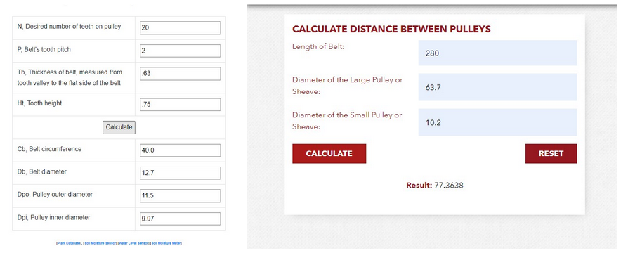
To find the outer diameter of the pulley: click here
To find the distance between the pulleys: click here
The distance between the stepper motor pulley and the Centre “smaller” pulley= 89.725mm
The distance between the Centre pulley and the last “bigger” pulley= 74.882mm
Components used in this design:
- belts
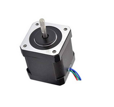
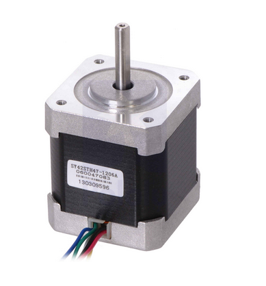
- NEMA 14 stepper motor 👇🏼
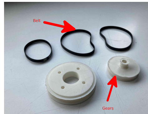
- 3D printed pulleys
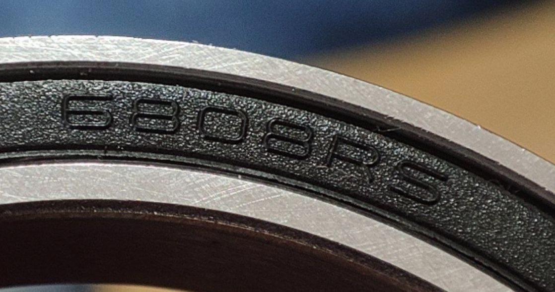
- bearing
with these values, and components in mind, I started designing the ARM
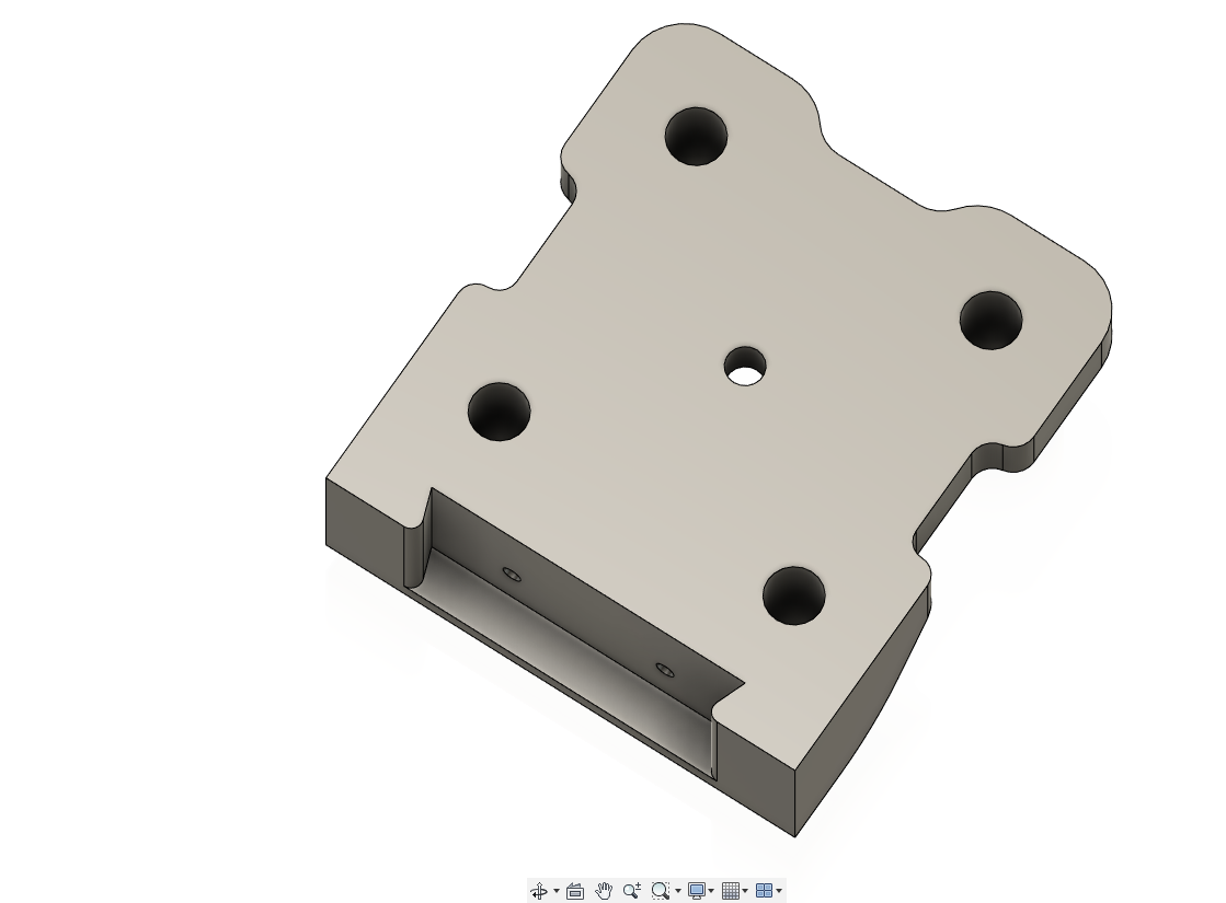
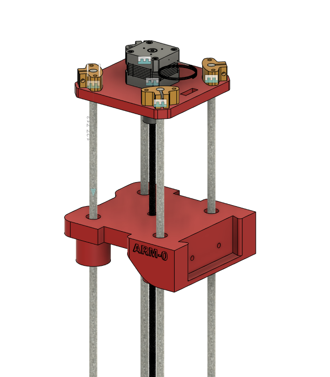
- the arm was designed in 2 pieces
- this is the part that will be moving on the z-axis
- first I sketched a layout based on the calculations done above
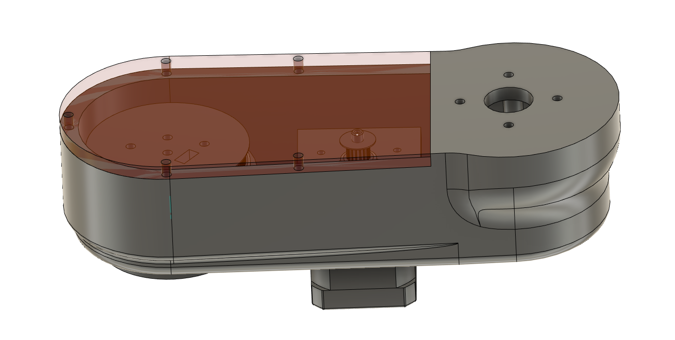
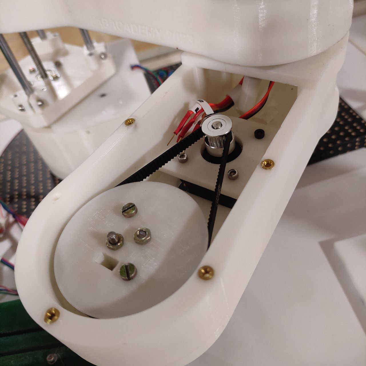
- then I made it into 3D, gave pockets for placing bearings
- and placed all the components to check the clearance
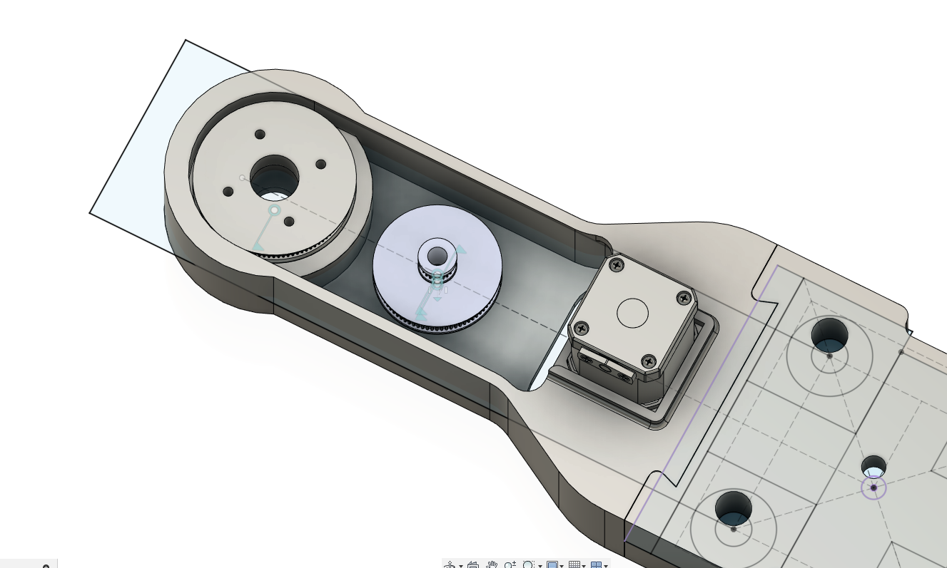
- we used Nema 14 stepper motor, so I had to design a base for that in the arm
- I also have added a dove tale at the end for easier assembly and disassembly
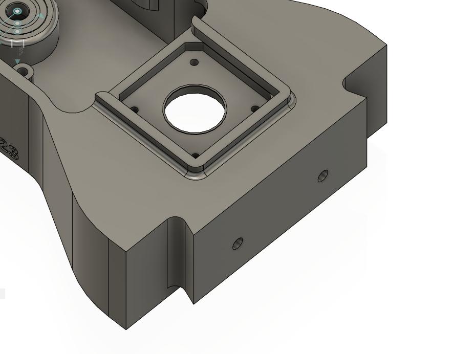
this was very helpful while assembling because we had to assemble and disassemble the components a couple of times, so if we were only relying on the bolts it would have been a big hassle, at this time we fixed the parts with the bolt only after all the testing where completed
- also designed a cover that will be then laser cut out of an acrylic sheet
- the part is now almost ready, it can be 3D printed now, but it is better to print it after designing the 2nd arm “the elbow” since some changes will be needed to be made to arm 1, so it's better to print when the design is final.
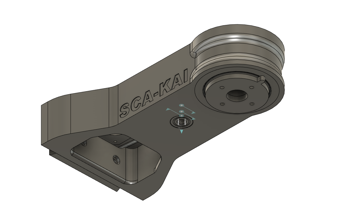
Arm 2 “The Elbow”
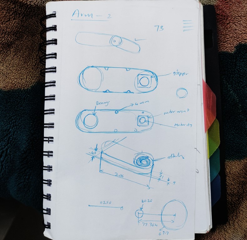
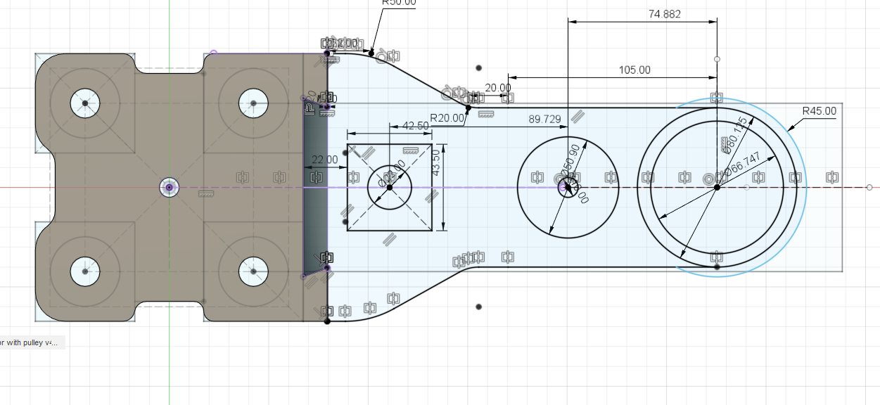
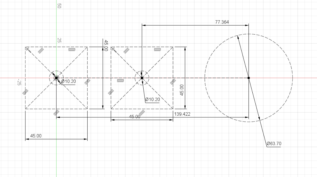
- the same calculations were also made here for finding the distance between the pulleys and the dia of the pulley
The Gear ratio of the second arm= 100 : 80 : 16
The distances are:
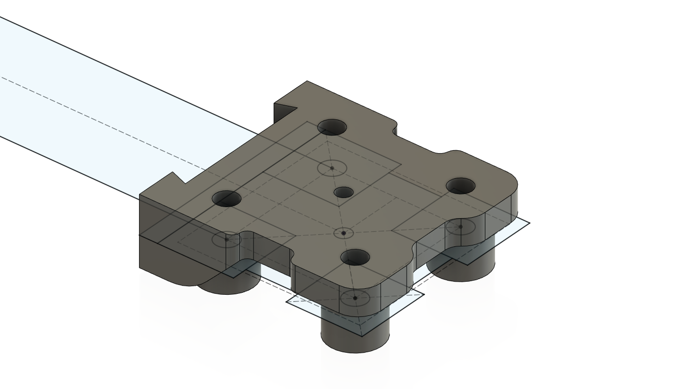
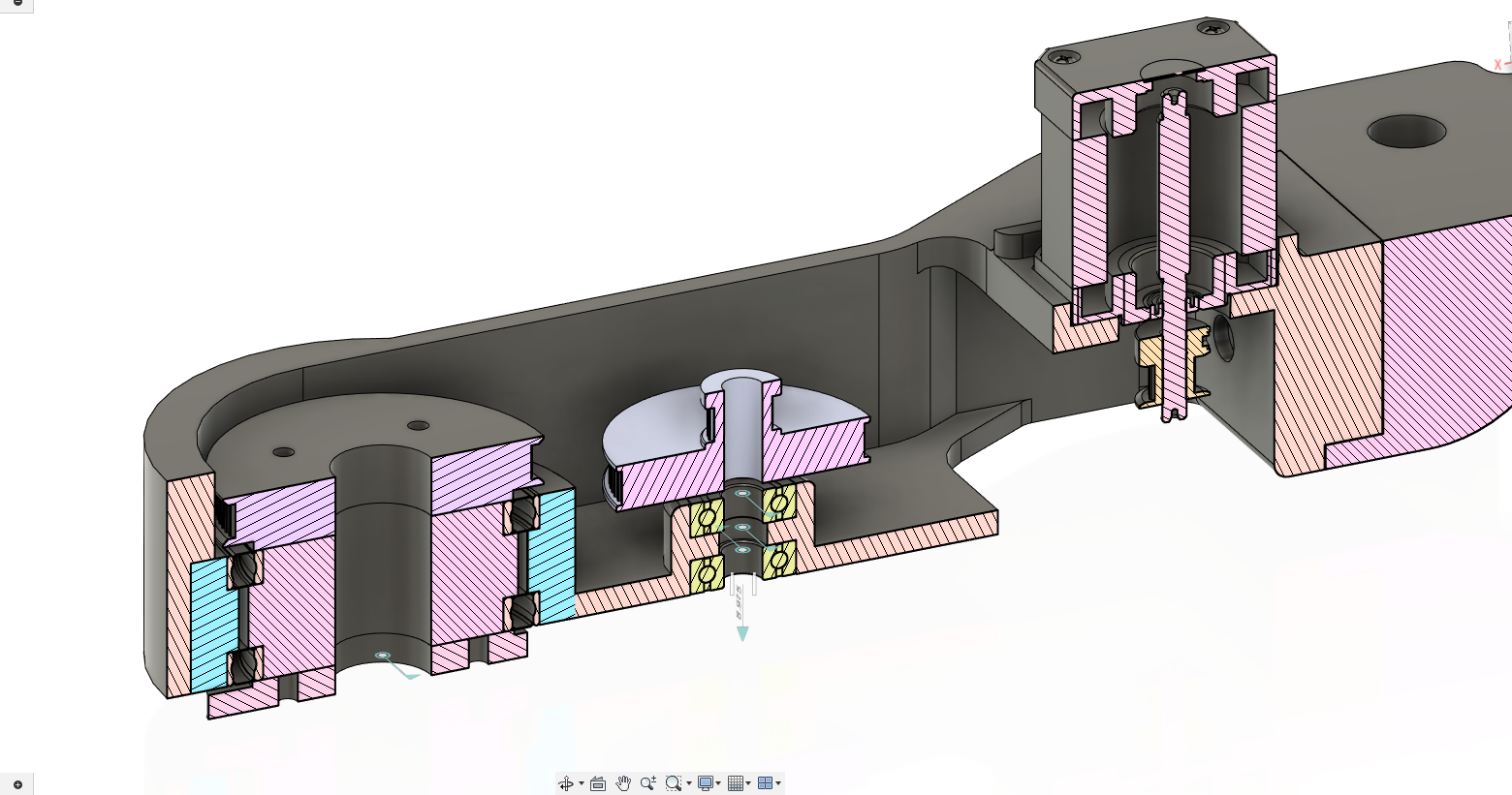
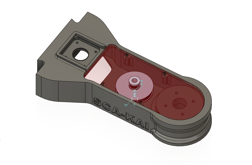
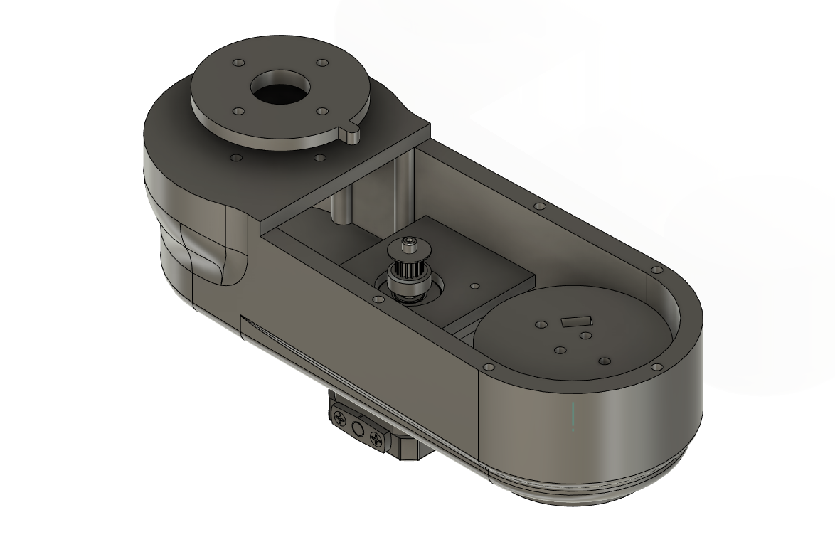
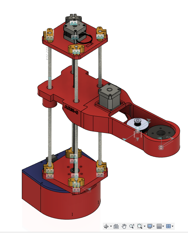
- the cad design of the second arm
- Outline sketch based on the calculations
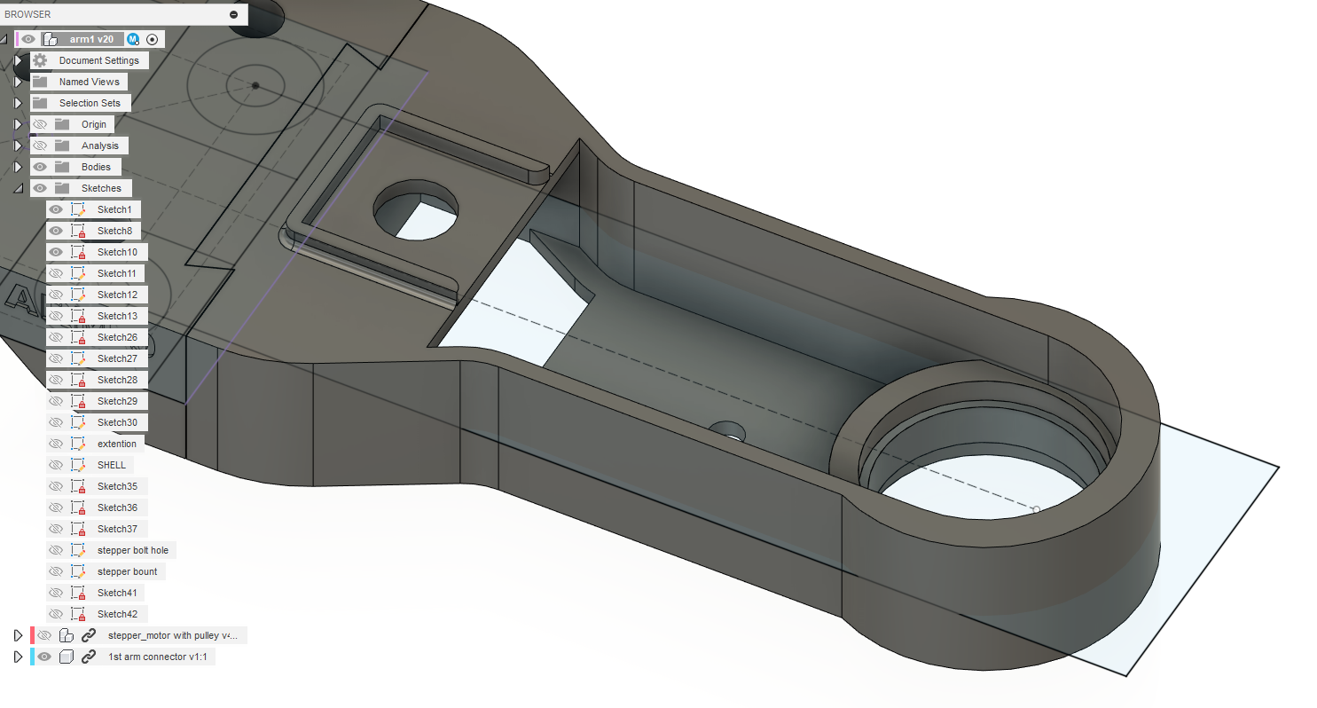
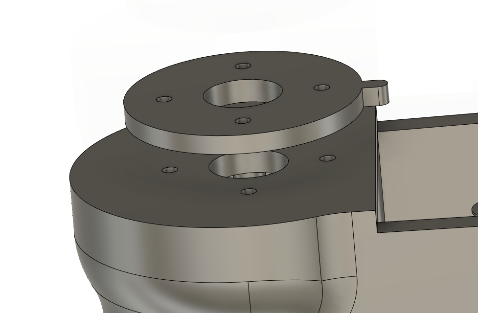
- attachment to the arm 1
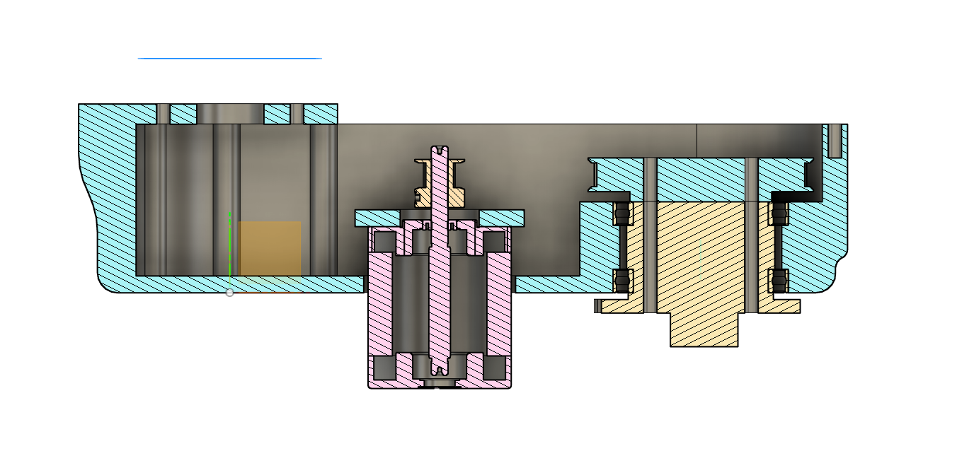
- section view
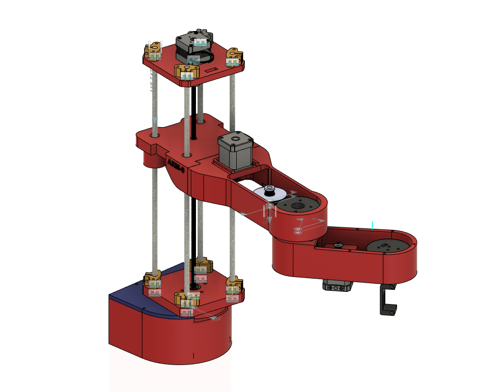
- the end effector was designed by Praveen, so I took some details from his design and made changes to my design to fit the end effector to the arm correctly
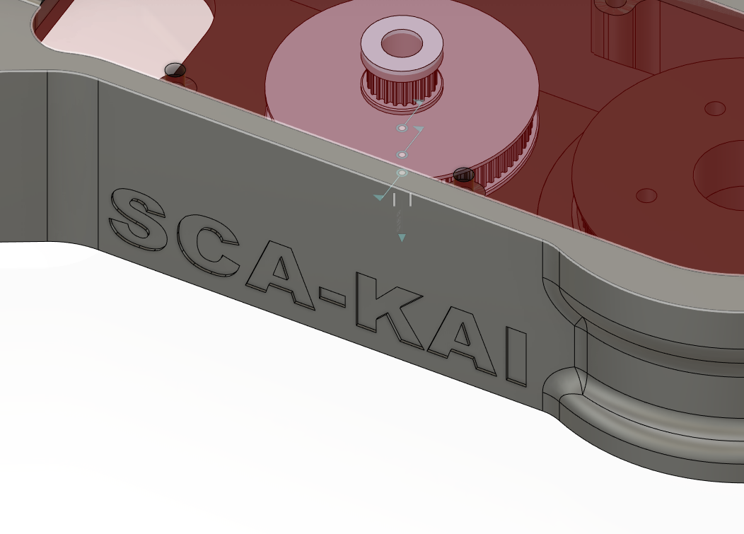
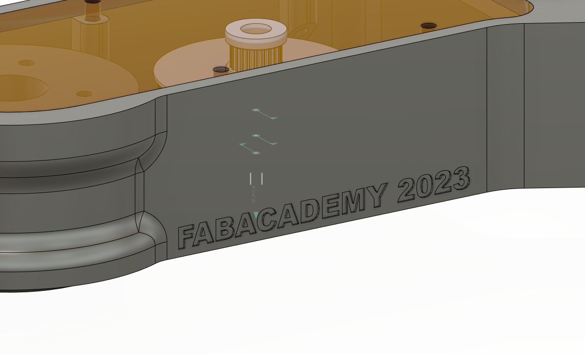
- adding details, to make it unique I added some details on the parts
- now this was saved as stl and sent for 3D printing.
- it was 3D printed in PRUSA mk3s 3D printer, and it took 23 hours,
- since we have 5 Prusa’s printed it was convenient for us to print all the parts at the same time.
3D printed parts
- by this time the base was already made and assembled by Sreyas and Praveen ji
- assembling the parts
- after assembling the components in the 3D-printed arms
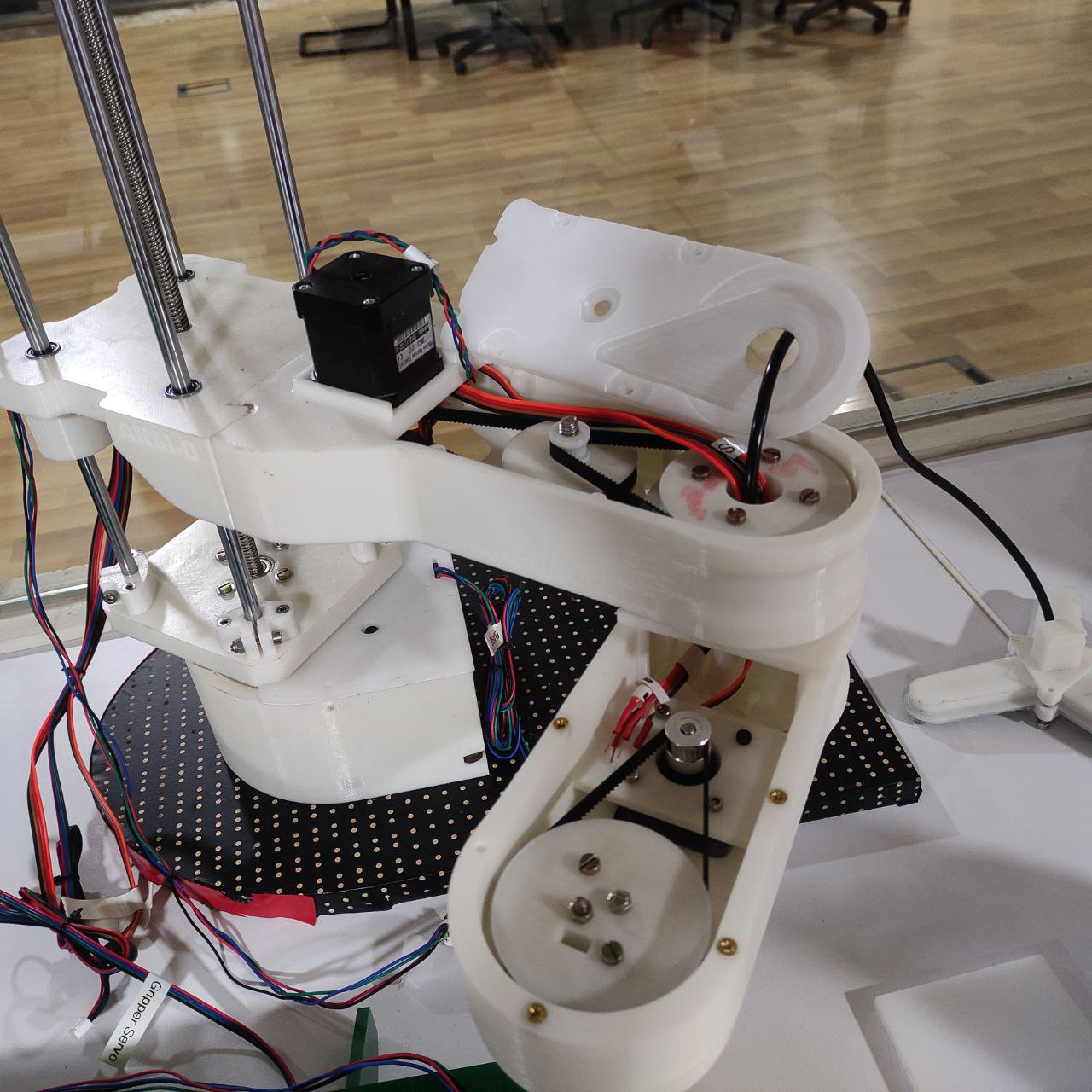
- temporary assembly for testing, here it was just fixed with the dovetail fit
testing
Sibin was in charge of programming testing and debugging so I assisted him in testing the components
- we used Marlin firmware which is commonly used for 3D printers but can also be used for other types of machines, including SCARA robots. The reason Marlin was used for SCA-KAI is that it provides a reliable and flexible platform for controlling and communicating with the robot's motors and sensors.
- testing the rotation
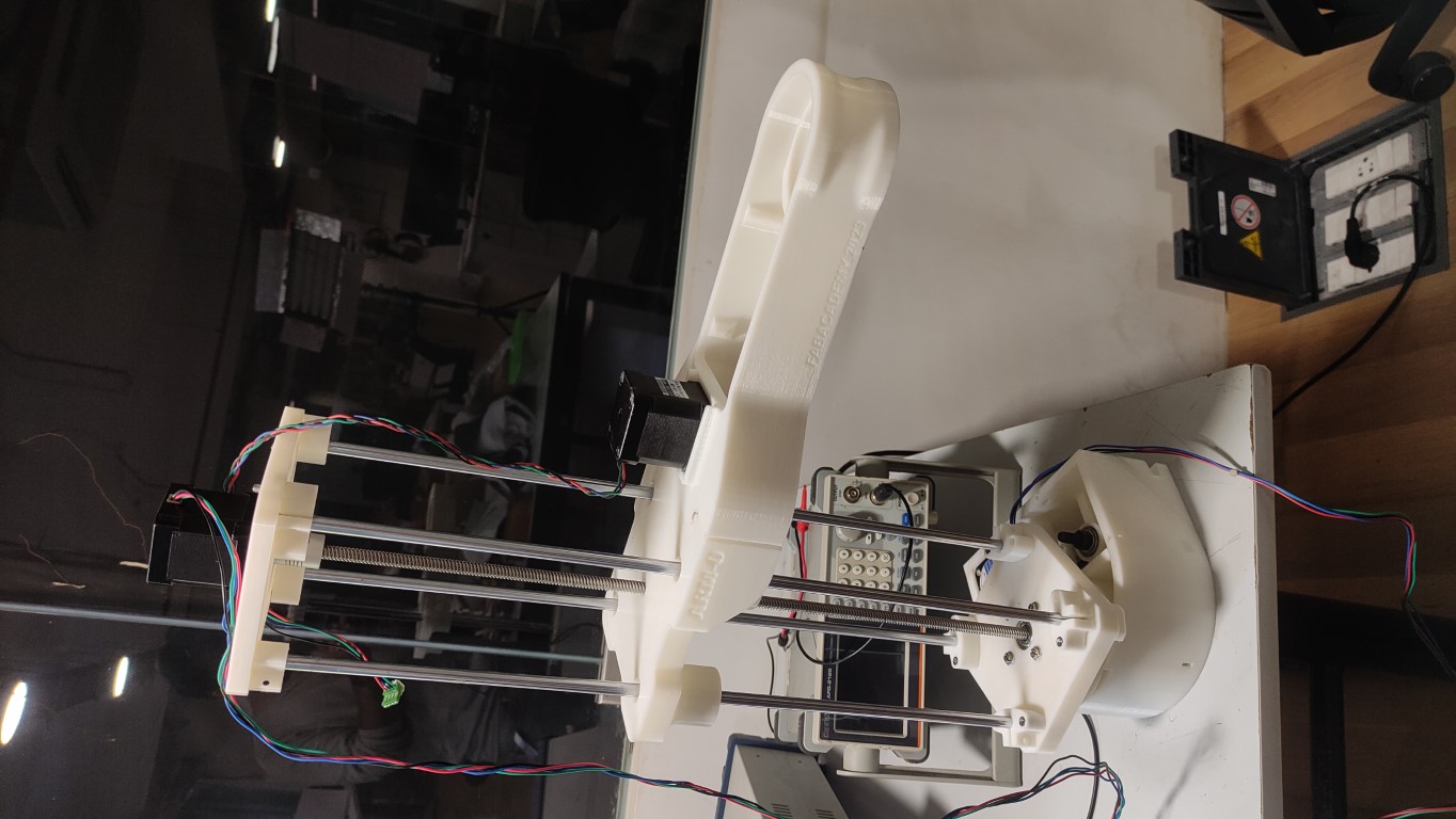
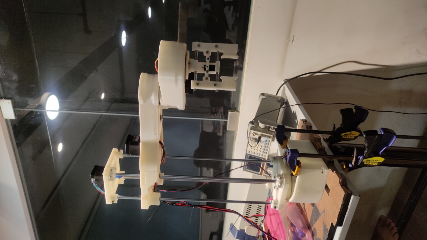
- Final assembly
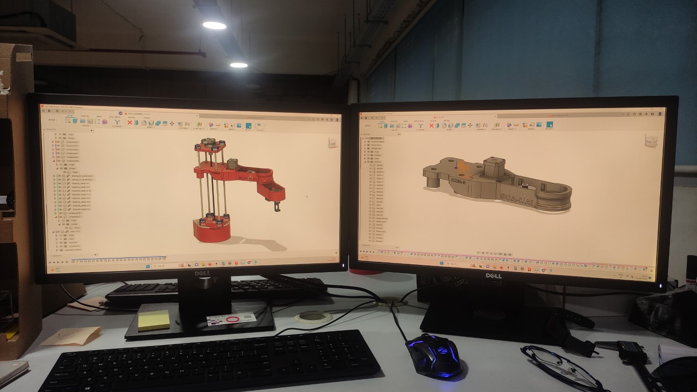
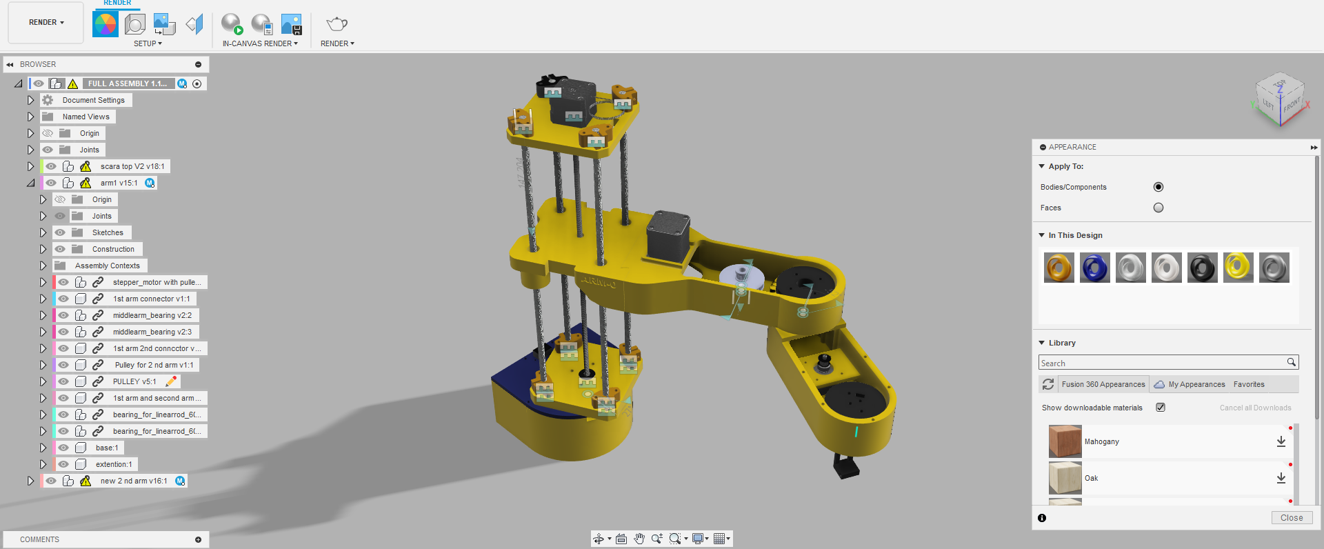
Full assembly in CAD and rendering
on the side, the parts are being assembled and tested I had to create a whole working model in the CAD for rendering,
- We can see all the moments in assembly
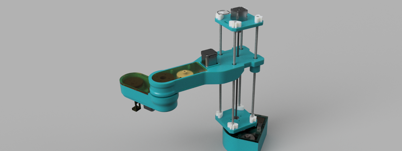
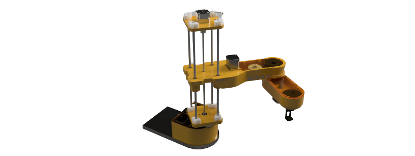
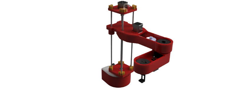
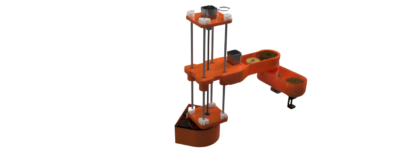
Rendering
rendering in fusion 360
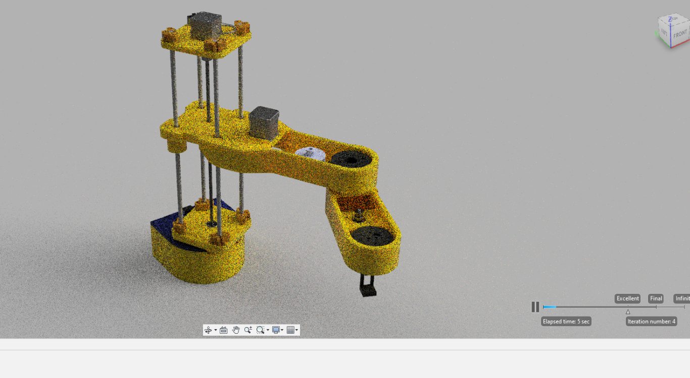
- these are some of the rendered images
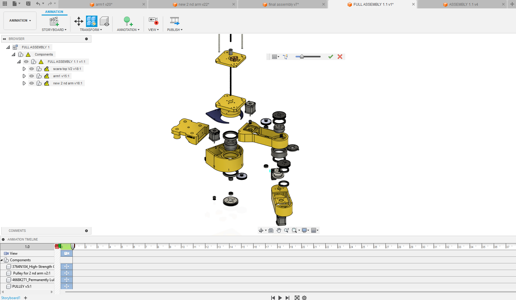
Animation
- animating in the fusion 360
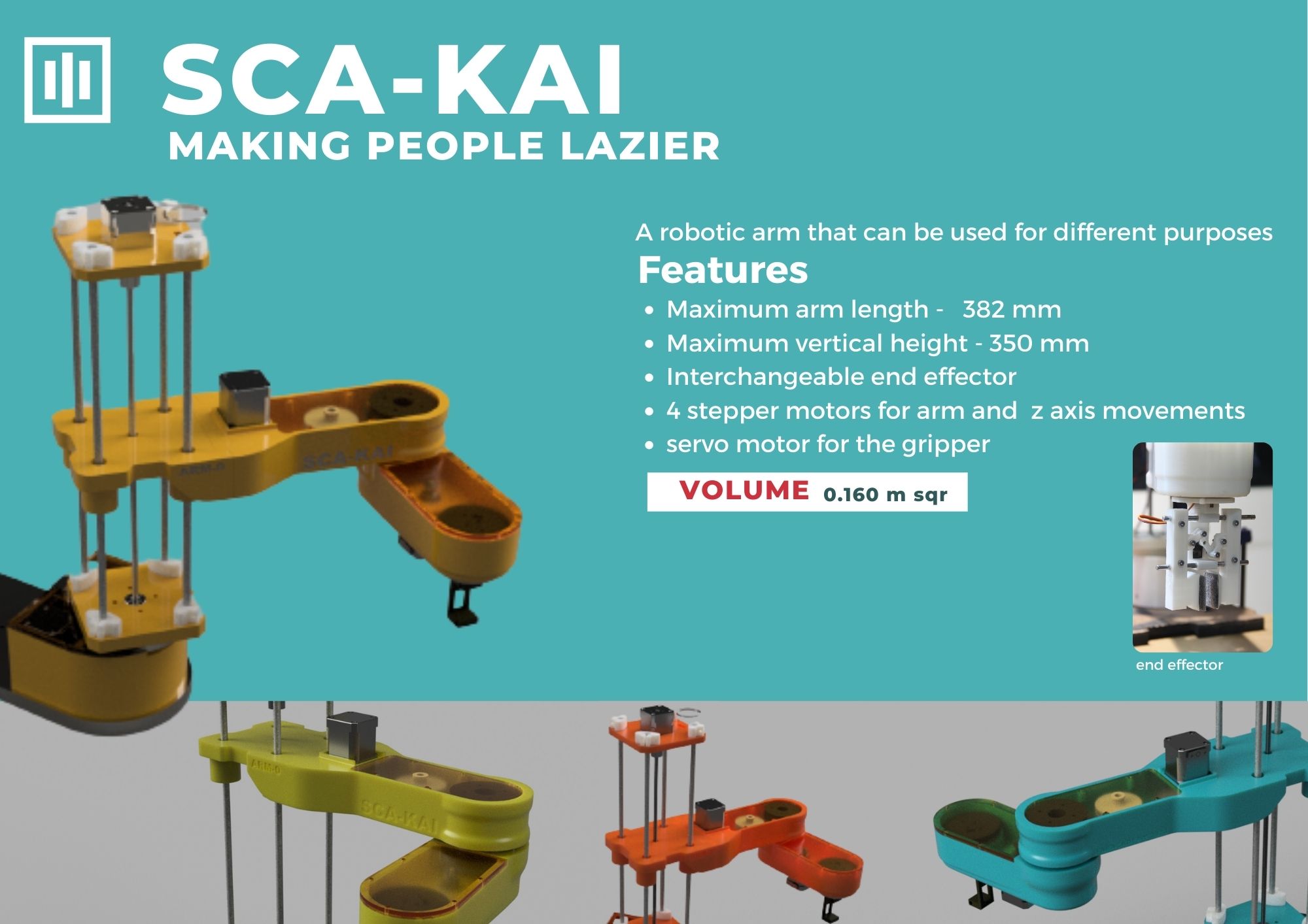
Poster for the project
now the project is almost complete, and the testing was successful. we had to make a poster to showcase our project highlighting the features of this project
- designing the poster in Canva
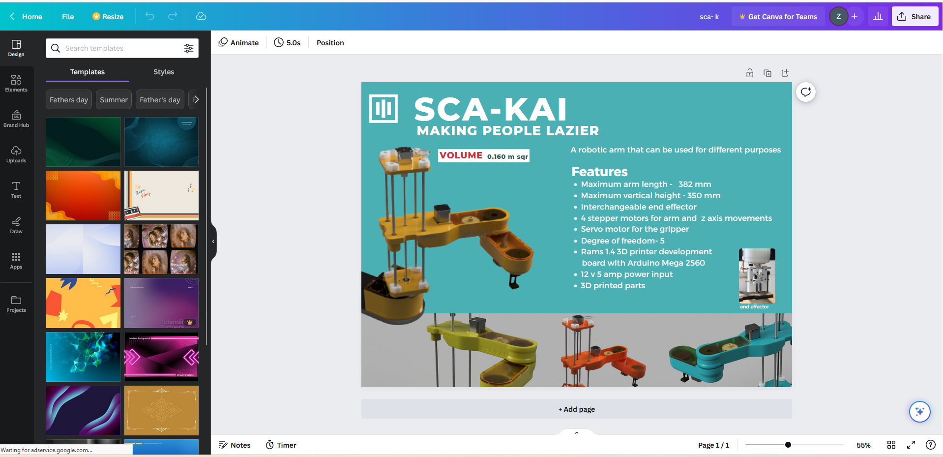
The poster
Design files
The design files are shared on the group assignment page