Week 4: Embedded Programming
Tasks for this week
Group assignment
- Compare the performance and development workflows for other architectures
- Document your work to the group work page and reflect on your individual page what you learned
Individual assignment
- Browse through the datasheet for your microcontroller
- Program a microcontroller development board to interact and communicate
Group Assignment
Link to Group Assignment
We tried a number of boards. Not all boards use the same interface for programming, and some have a number you can choose from in addition to more than one type of programming language.
I was excited that I got to try out programming the Xiao RP2040 as it will be used in future assignments and my final project. I found it relatively easy to program.
Microcontroller Datasheet Review - Arduino Uno
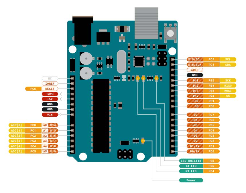
For this week's individual assignment I am going to look at and use and Arduino Uno R3
To demonstrate my browsing of the datasheet I have answered a number of questions below:
-
What is the name of the microcontroller (MCU)?
Arduino Uno R3, it uses a ATmega328P Processor -
What type of 'architecture' is it?
The board uses an 8-bit AVR® RISC-based ATMega16U2 Processor, which uses the Harvard architecture -
What is its Clock Speed?
Up to 16 MHz -
What different types of memory does it have? How much of each?
32KB Flash, 2KB SRAM and 1KB EEPROM -
How many pins does the MCU have?
32 pins -
How many GPIO pins?
10 GPIO pins -
How many Digital pins? What are their pin numbers?
17 pins labeled on the board as 0 to 13, AREF and unlabled Pin 17 and 18 -
How many Analog pins? What are their pin numbers?
6 pins labeled A0 to A5 -
How many pins capable of PWM?
6 pins labeled 3, 5, 6, 9, 10 and 11 -
What types of Communication Protocol can the MCU do (ISP, UPDI, Serial, etc.)?
Serial, I2C, Serial Peripheral Interface (SPI) -
What (fancy) extra features..."hardware peripherals" does the MCU have (DAC, ADC, etc)
- 2x 8-bit Timer/Counter with a dedicated period register and compare channels
- 1x 16-bit Timer/Counter with a dedicated period register, input capture and compare channels
- 1x USART with fractional baud rate generator and start-of-frame detection
- Watchdog Timer with separate on-chip oscillator
- Interrupt and wake-up on pin change
- What power requirements/limitations?
Input power supply of 2.7-5.5 volts required to run board
Programming an Arduino Uno
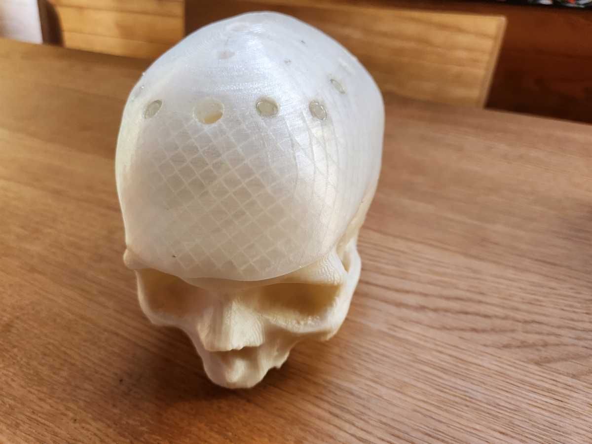
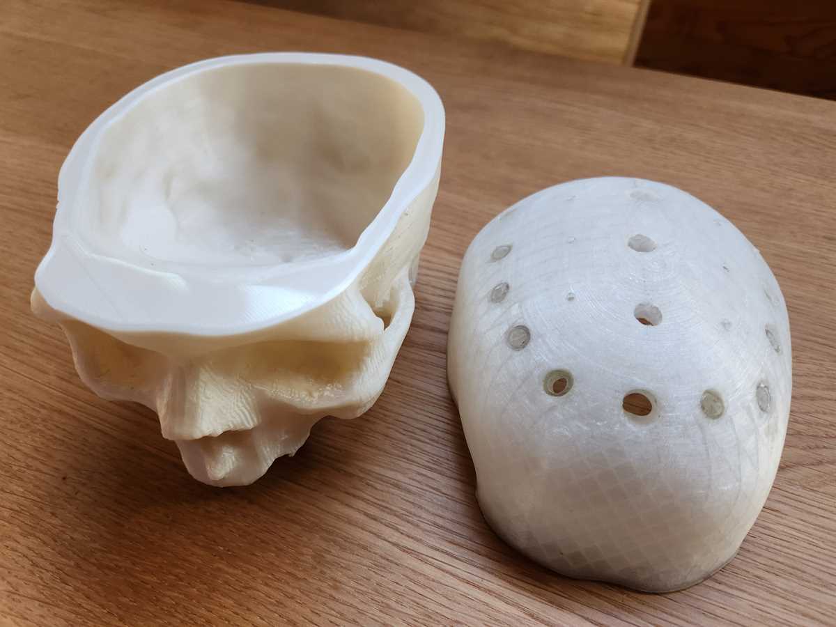
I am helping one of the users in my lab (a retired Doctor) to build a skull that lights up to be a prop/extra communication item for presentations on the impact of concussion on the brain. The Arduino Uno used came from the user.
The Skull has been 3D printed by the user and has holes drilled in it for the lights to go in. It is in two parts so wiring can be put inside, also to make it easy to print.
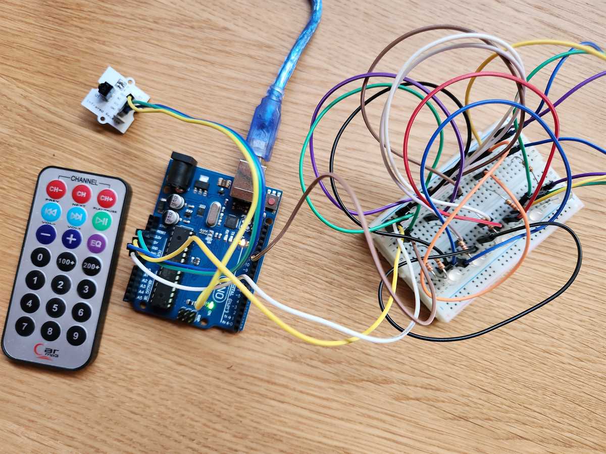
I am using this assignment to do a breadboard test of the wiring before soldering.
The Arduino Uno is connected to a set of individually addressable RGB LEDs and an IR receiver that can receive signals from a remote during the presentation.
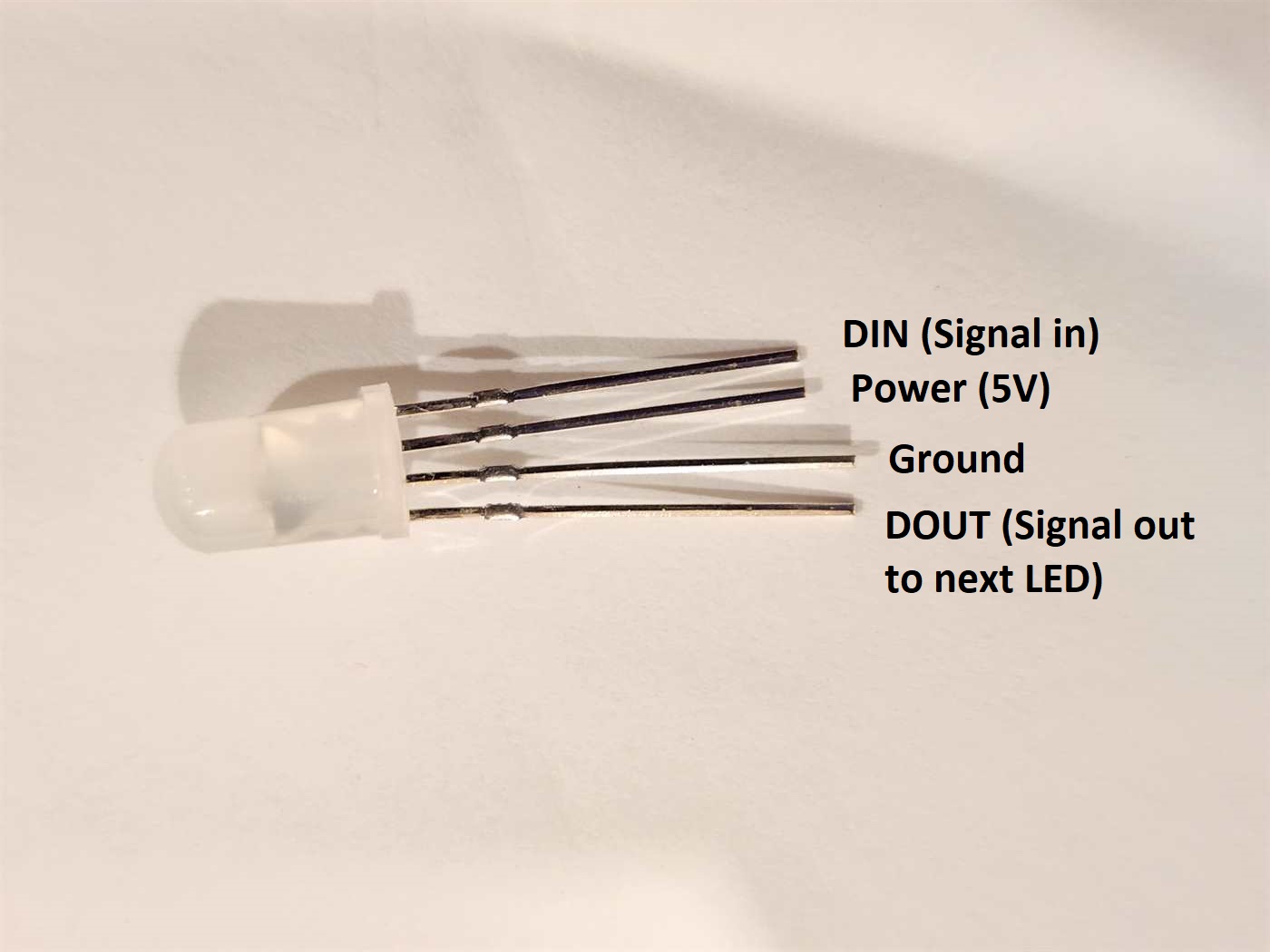
I used Popolu 2535 Addressable RGB LEDs
These LEDs are the same type you would find in a string of consumer LED lights that can be programmed to individually change colours, like transitioning along the string through a rainbow of colours.
These LEDs have four pins on them for signal in, power, ground and signal out.
Pin out
IR Remote:
- Yellow wire: signal - Digital Pin 2
- Green wire: power - Analog Pin 4 - 3V3
- Blue wire: ground - Analog Pin 6 - Ground
Addressable LEDs
- Brown wire: signal DIN - Digital Pin 6
- Yellow wire: power - Analog Pin 5 - 5V
- White wire: ground - Analog Pin 7 - Ground
All the addressable LEDs connect to the power and ground rails on the breadboad.
The first LED's DIN is connected to the Arduino and its DOUT is connected to the DIN for the next LED. Each LED then has its DOUT to DIN connected to send the signal along the line.
2.2 Ohm resistors (these came in a kit with the Arduino Uno) have been used between the board power and the LEDs to help prevent overloading and burning out the LEDs. This resistor has also been used between the board and the first LED's DIN to support signal integrity.
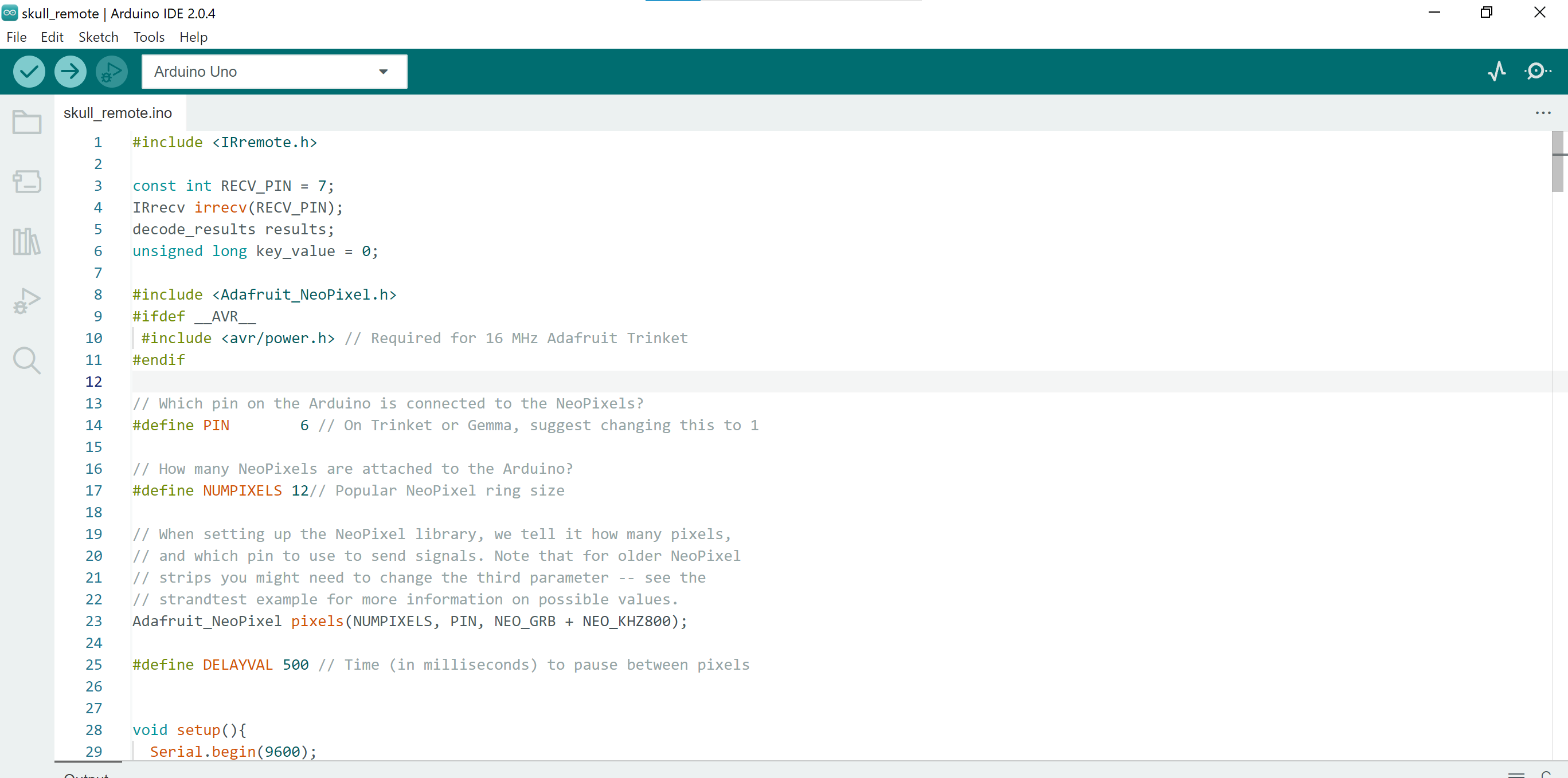
Code
The Arduino uses its own programming language and can be programmed and run via Arduino IDE. I used version Arduino IDE 2.0.4.
IR Remote Sample Code
Note to make the below code work, you will need to install the IR remote library into your Arduino IDE Link
For the IR Remote I used the following sample code. This gave me the code to be able to read the signal of the remote. Note that there is a PinDefinitionsAndMore.h file that needs to go with this code as a reference for it to run. When testing this code I found for the Arduino Uno, that pin 2 is the standard pin used for reading the IR Remote signal for this code. I also tested what number comes back for IrReceiver.decodedIRData.command when clicking each of the buttons on the remote I wanted to code for.
/*
 * SimpleReceiver.cpp
 *
 * Demonstrates receiving NEC IR codes with IRremote
 *
 *  This file is part of Arduino-IRremote https://github.com/Arduino-IRremote/Arduino-IRremote.
 *
 ************************************************************************************
 * MIT License
 *
 * Copyright (c) 2020-2023 Armin Joachimsmeyer
 *
 * Permission is hereby granted, free of charge, to any person obtaining a copy
 * of this software and associated documentation files (the "Software"), to deal
 * in the Software without restriction, including without limitation the rights
 * to use, copy, modify, merge, publish, distribute, sublicense, and/or sell
 * copies of the Software, and to permit persons to whom the Software is furnished
 * to do so, subject to the following conditions:
 *
 * The above copyright notice and this permission notice shall be included in all
 * copies or substantial portions of the Software.
 *
 * THE SOFTWARE IS PROVIDED "AS IS", WITHOUT WARRANTY OF ANY KIND, EXPRESS OR IMPLIED,
 * INCLUDING BUT NOT LIMITED TO THE WARRANTIES OF MERCHANTABILITY, FITNESS FOR A
 * PARTICULAR PURPOSE AND NONINFRINGEMENT. IN NO EVENT SHALL THE AUTHORS OR COPYRIGHT
 * HOLDERS BE LIABLE FOR ANY CLAIM, DAMAGES OR OTHER LIABILITY, WHETHER IN AN ACTION OF
 * CONTRACT, TORT OR OTHERWISE, ARISING FROM, OUT OF OR IN CONNECTION WITH THE SOFTWARE
 * OR THE USE OR OTHER DEALINGS IN THE SOFTWARE.
 *
 ************************************************************************************
 */

/*
 * Specify which protocol(s) should be used for decoding.
 * If no protocol is defined, all protocols (except Bang&Olufsen) are active.
 * This must be done before the #include <IRremote.hpp>
 */
//#define DECODE_DENON        // Includes Sharp
//#define DECODE_JVC
//#define DECODE_KASEIKYO
//#define DECODE_PANASONIC    // alias for DECODE_KASEIKYO
//#define DECODE_LG
#define DECODE_NEC          // Includes Apple and Onkyo
//#define DECODE_SAMSUNG
//#define DECODE_SONY
//#define DECODE_RC5
//#define DECODE_RC6

//#define DECODE_BOSEWAVE
//#define DECODE_LEGO_PF
//#define DECODE_MAGIQUEST
//#define DECODE_WHYNTER
//#define DECODE_FAST

//#define DECODE_DISTANCE_WIDTH // Universal decoder for pulse distance width protocols
//#define DECODE_HASH         // special decoder for all protocols

//#define DECODE_BEO          // This protocol must always be enabled manually, i.e. it is NOT enabled if no protocol is defined. It prevents decoding of SONY!

//#define DEBUG               // Activate this for lots of lovely debug output from the decoders.

//#define RAW_BUFFER_LENGTH  180  // Default is 112 if DECODE_MAGIQUEST is enabled, otherwise 100.

#include <Arduino.h>

/*
 * This include defines the actual pin number for pins like IR_RECEIVE_PIN, IR_SEND_PIN for many different boards and architectures
 */
#include "PinDefinitionsAndMore.h"
#include <IRremote.hpp> // include the library

void setup() {
    Serial.begin(115200);
    // Just to know which program is running on my Arduino
    Serial.println(F("START " __FILE__ " from " __DATE__ "\r\nUsing library version " VERSION_IRREMOTE));

    // Start the receiver and if not 3. parameter specified, take LED_BUILTIN pin from the internal boards definition as default feedback LED
    IrReceiver.begin(IR_RECEIVE_PIN, ENABLE_LED_FEEDBACK);

    Serial.print(F("Ready to receive IR signals of protocols: "));
    printActiveIRProtocols(&Serial);
    Serial.println(F("at pin " STR(IR_RECEIVE_PIN)));
}

void loop() {
    /*
     * Check if received data is available and if yes, try to decode it.
     * Decoded result is in the IrReceiver.decodedIRData structure.
     *
     * E.g. command is in IrReceiver.decodedIRData.command
     * address is in command is in IrReceiver.decodedIRData.address
     * and up to 32 bit raw data in IrReceiver.decodedIRData.decodedRawData
     */
    if (IrReceiver.decode()) {

        /*
         * Print a short summary of received data
         */
        IrReceiver.printIRResultShort(&Serial);
        IrReceiver.printIRSendUsage(&Serial);
        if (IrReceiver.decodedIRData.protocol == UNKNOWN) {
            Serial.println(F("Received noise or an unknown (or not yet enabled) protocol"));
            // We have an unknown protocol here, print more info
            IrReceiver.printIRResultRawFormatted(&Serial, true);
        }
        Serial.println();

        /*
         * !!!Important!!! Enable receiving of the next value,
         * since receiving has stopped after the end of the current received data packet.
         */
        IrReceiver.resume(); // Enable receiving of the next value

        /*
         * Finally, check the received data and perform actions according to the received command
         */
        if (IrReceiver.decodedIRData.command == 0x10) {
            // do something
        } else if (IrReceiver.decodedIRData.command == 0x11) {
            // do something else
        }
    }
}
PinDefinitionAndMore.h
/*
 *  PinDefinitionsAndMore.h
 *
 *  Contains pin definitions for IRremote examples for various platforms
 *  as well as definitions for feedback LED and tone() and includes
 *
 *  Copyright (C) 2021-2022  Armin Joachimsmeyer
 *  armin.joachimsmeyer@gmail.com
 *
 *  This file is part of IRremote https://github.com/Arduino-IRremote/Arduino-IRremote.
 *
 *  Arduino-IRremote is free software: you can redistribute it and/or modify
 *  it under the terms of the GNU General Public License as published by
 *  the Free Software Foundation, either version 3 of the License, or
 *  (at your option) any later version.
 *
 *  This program is distributed in the hope that it will be useful,
 *  but WITHOUT ANY WARRANTY; without even the implied warranty of
 *  MERCHANTABILITY or FITNESS FOR A PARTICULAR PURPOSE.
 *  See the GNU General Public License for more details.
 *
 *  You should have received a copy of the GNU General Public License
 *  along with this program. If not, see <http://www.gnu.org/licenses/gpl.html>.
 *
 */

/*
 * Pin mapping table for different platforms
 *
 * Platform     IR input    IR output   Tone      Core/Pin schema
 * --------------------------------------------------------------
 * DEFAULT/AVR  2           3           4         Arduino
 * ATtinyX5     0|PB0       4|PB4       3|PB3     ATTinyCore
 * ATtiny167    3|PA3       2|PA2       7|PA7     ATTinyCore
 * ATtiny167    9|PA3       8|PA2       5|PA7     Digispark pro
 * ATtiny3217  18|PA1      19|PA2      20|PA3     MegaTinyCore
 * ATtiny1604   2           3|PA5       %
 * ATtiny816   14|PA1      16|PA3       1|PA5     MegaTinyCore
 * ATtiny1614   8|PA1      10|PA3       1|PA5     MegaTinyCore
 * SAMD21       3           4           5
 * ESP8266      14|D5       12|D6       %
 * ESP32        15          4           27
 * BluePill     PA6         PA7         PA3
 * APOLLO3      11          12          5
 * RP2040       3|GPIO15    4|GPIO16    5|GPIO17
 */
//#define _IR_MEASURE_TIMING // For debugging purposes.

#if defined(__AVR__)
#if defined(__AVR_ATtiny25__) || defined(__AVR_ATtiny45__) || defined(__AVR_ATtiny85__) // Digispark board
#include "ATtinySerialOut.hpp" // TX is at pin 2 - Available as Arduino library "ATtinySerialOut". Saves 700 bytes program memory and 70 bytes RAM for ATtinyCore
#define IR_RECEIVE_PIN  0
#define IR_SEND_PIN     4 // Pin 2 is serial output with ATtinySerialOut. Pin 1 is internal LED and Pin3 is USB+ with pullup on Digispark board.
#define TONE_PIN        3
#define _IR_TIMING_TEST_PIN 3

#  elif defined(__AVR_ATtiny87__) || defined(__AVR_ATtiny167__) // Digispark pro board
#include "ATtinySerialOut.hpp" // Available as Arduino library "ATtinySerialOut"
// For ATtiny167 Pins PB6 and PA3 are usable as interrupt source.
#  if defined(ARDUINO_AVR_DIGISPARKPRO)
#define IR_RECEIVE_PIN   9 // PA3 - on Digispark board labeled as pin 9
//#define IR_RECEIVE_PIN  14 // PB6 / INT0 is connected to USB+ on DigisparkPro boards
#define IR_SEND_PIN      8 // PA2 - on Digispark board labeled as pin 8
#define TONE_PIN         5 // PA7 - on Digispark board labeled as pin 5
#define _IR_TIMING_TEST_PIN 10 // PA4
#  else
#define IR_RECEIVE_PIN  3 // PA3 - on Digispark board labeled as pin 9
#define IR_SEND_PIN     2 // PA2 - on Digispark board labeled as pin 8
#define TONE_PIN        7 // PA7 - on Digispark board labeled as pin 5
#  endif

#  elif defined(__AVR_ATtiny88__) // MH-ET Tiny88 board
#include "ATtinySerialOut.hpp" // Available as Arduino library "ATtinySerialOut". Saves 128 bytes program memory
// Pin 6 is TX pin 7 is RX
#define IR_RECEIVE_PIN   3 // INT1
#define IR_SEND_PIN      4
#define TONE_PIN         9
#define _IR_TIMING_TEST_PIN 8

#  elif defined(__AVR_ATtiny1616__)  || defined(__AVR_ATtiny3216__) || defined(__AVR_ATtiny3217__) // Tiny Core Dev board
#define IR_RECEIVE_PIN  18
#define IR_SEND_PIN     19
#define TONE_PIN        20
#define APPLICATION_PIN  0 // PA4
#undef LED_BUILTIN         // No LED available on the TinyCore 32 board, take the one on the programming board which is connected to the DAC output
#define LED_BUILTIN      2 // PA6

#  elif defined(__AVR_ATtiny816__) // Tiny Core Micro
#define IR_RECEIVE_PIN  14 // PA1
#define IR_SEND_PIN     16 // PA3
#define TONE_PIN         1 // PA5
#define APPLICATION_PIN  0 // PA4
#undef LED_BUILTIN         // No LED available, take the one which is connected to the DAC output
#define LED_BUILTIN      4 // PB5

#  elif defined(__AVR_ATtiny1614__)
#define IR_RECEIVE_PIN   8 // PA1
#define IR_SEND_PIN     10 // PA3
#define TONE_PIN         1 // PA5
#define APPLICATION_PIN  0 // PA4

#  elif defined(__AVR_ATtiny1604__)
#define IR_RECEIVE_PIN   2 // To be compatible with interrupt example, pin 2 is chosen here.
#define IR_SEND_PIN      3
#define APPLICATION_PIN  5

#define tone(...) void()      // Define as void, since TCB0_INT_vect is also used by tone()
#define noTone(a) void()
#define TONE_PIN        42 // Dummy for examples using it

#  elif defined(__AVR_ATmega1284__) || defined(__AVR_ATmega1284P__) \
|| defined(__AVR_ATmega644__) || defined(__AVR_ATmega644P__) \
|| defined(__AVR_ATmega324P__) || defined(__AVR_ATmega324A__) \
|| defined(__AVR_ATmega324PA__) || defined(__AVR_ATmega164A__) \
|| defined(__AVR_ATmega164P__) || defined(__AVR_ATmega32__) \
|| defined(__AVR_ATmega16__) || defined(__AVR_ATmega8535__) \
|| defined(__AVR_ATmega64__) || defined(__AVR_ATmega128__) \
|| defined(__AVR_ATmega1281__) || defined(__AVR_ATmega2561__) \
|| defined(__AVR_ATmega8515__) || defined(__AVR_ATmega162__)
#define IR_RECEIVE_PIN      2
#define IR_SEND_PIN        13
#define TONE_PIN            4
#define APPLICATION_PIN     5
#define ALTERNATIVE_IR_FEEDBACK_LED_PIN 6 // E.g. used for examples which use LED_BUILDIN for example output.
#define _IR_TIMING_TEST_PIN 7

#  else // Default as for ATmega328 like on Uno, Nano, Leonardo, Teensy 2.0 etc.
#define IR_RECEIVE_PIN      2 // To be compatible with interrupt example, pin 2 is chosen here.
#define IR_SEND_PIN         3
#define TONE_PIN            4
#define APPLICATION_PIN     5
#define ALTERNATIVE_IR_FEEDBACK_LED_PIN 6 // E.g. used for examples which use LED_BUILDIN for example output.
#define _IR_TIMING_TEST_PIN 7

#    if defined(ARDUINO_AVR_PROMICRO) // Sparkfun Pro Micro is __AVR_ATmega32U4__ but has different external circuit
// We have no built in LED at pin 13 -> reuse RX LED
#undef LED_BUILTIN
#define LED_BUILTIN         LED_BUILTIN_RX
#    endif
#  endif // defined(__AVR_ATtiny25__)...

#elif defined(ESP8266)
#define FEEDBACK_LED_IS_ACTIVE_LOW // The LED on my board (D4) is active LOW
#define IR_RECEIVE_PIN          14 // D5
#define IR_SEND_PIN             12 // D6 - D4/pin 2 is internal LED
#define _IR_TIMING_TEST_PIN      2 // D4
#define APPLICATION_PIN         13 // D7

#define tone(...) void()      // tone() inhibits receive timer
#define noTone(a) void()
#define TONE_PIN                42 // Dummy for examples using it

#elif defined(CONFIG_IDF_TARGET_ESP32C3)
#define IR_INPUT_PIN             8
#define IR_SEND_PIN              9
#define TONE_PIN                10 // ADC2_0
#define APPLICATION_PIN         11

#elif defined(ESP32)
#include <Arduino.h>

// tone() is included in ESP32 core since 2.0.2
#if !defined(ESP_ARDUINO_VERSION_VAL)
#define ESP_ARDUINO_VERSION_VAL(major, minor, patch) 12345678
#endif
#if ESP_ARDUINO_VERSION  <= ESP_ARDUINO_VERSION_VAL(2, 0, 2)
#define TONE_LEDC_CHANNEL        1  // Using channel 1 makes tone() independent of receiving timer -> No need to stop receiving timer.
void tone(uint8_t aPinNumber, unsigned int aFrequency){
    ledcAttachPin(aPinNumber, TONE_LEDC_CHANNEL);
    ledcWriteTone(TONE_LEDC_CHANNEL, aFrequency);
}
void tone(uint8_t aPinNumber, unsigned int aFrequency, unsigned long aDuration){
    ledcAttachPin(aPinNumber, TONE_LEDC_CHANNEL);
    ledcWriteTone(TONE_LEDC_CHANNEL, aFrequency);
    delay(aDuration);
    ledcWriteTone(TONE_LEDC_CHANNEL, 0);
}
void noTone(uint8_t aPinNumber){
    ledcWriteTone(TONE_LEDC_CHANNEL, 0);
}
#endif // ESP_ARDUINO_VERSION  <= ESP_ARDUINO_VERSION_VAL(2, 0, 2)

#define IR_RECEIVE_PIN          15  // D15
#define IR_SEND_PIN              4  // D4
#define TONE_PIN                27  // D27 25 & 26 are DAC0 and 1
#define APPLICATION_PIN         16  // RX2 pin

#elif defined(ARDUINO_ARCH_STM32) || defined(ARDUINO_ARCH_STM32F1) // BluePill
// Timer 3 blocks PA6, PA7, PB0, PB1 for use by Servo or tone()
#define IR_RECEIVE_PIN          PA6
#define IR_RECEIVE_PIN_STRING   "PA6"
#define IR_SEND_PIN             PA7
#define IR_SEND_PIN_STRING      "PA7"
#define TONE_PIN                PA3
#define _IR_TIMING_TEST_PIN     PA5
#define APPLICATION_PIN         PA2
#define APPLICATION_PIN_STRING  "PA2"
#  if defined(ARDUINO_GENERIC_STM32F103C) || defined(ARDUINO_BLUEPILL_F103C8)
// BluePill LED is active low
#define FEEDBACK_LED_IS_ACTIVE_LOW
#  endif

#elif defined(ARDUINO_ARCH_APOLLO3) // Sparkfun Apollo boards
#define IR_RECEIVE_PIN  11
#define IR_SEND_PIN     12
#define TONE_PIN         5

#elif defined(ARDUINO_ARCH_MBED) && defined(ARDUINO_ARCH_MBED_NANO) // Arduino Nano 33 BLE
#define IR_RECEIVE_PIN      3   // GPIO15 Start with pin 3 since pin 2|GPIO25 is connected to LED on Pi pico
#define IR_SEND_PIN         4   // GPIO16
#define TONE_PIN            5
#define APPLICATION_PIN     6
#define ALTERNATIVE_IR_FEEDBACK_LED_PIN 7 // E.g. used for examples which use LED_BUILDIN for example output.
#define _IR_TIMING_TEST_PIN 8

#elif defined(ARDUINO_ARCH_RP2040) // Arduino Nano Connect, Pi Pico with arduino-pico core https://github.com/earlephilhower/arduino-pico
#define IR_RECEIVE_PIN      15  // GPIO15 to be compatible with the Arduino Nano RP2040 Connect (pin3)
#define IR_SEND_PIN         16  // GPIO16
#define TONE_PIN            17
#define APPLICATION_PIN     18
#define ALTERNATIVE_IR_FEEDBACK_LED_PIN 19 // E.g. used for examples which use LED_BUILDIN for example output.
#define _IR_TIMING_TEST_PIN 20

// If you program the Nano RP2040 Connect with this core, then you must redefine LED_BUILTIN
// and use the external reset with 1 kOhm to ground to enter UF2 mode
#undef LED_BUILTIN
#define LED_BUILTIN          6

#elif defined(PARTICLE) // !!!UNTESTED!!!
#define IR_RECEIVE_PIN      A4
#define IR_SEND_PIN         A5 // Particle supports multiple pins

#define LED_BUILTIN         D7

/*
 * 4 times the same (default) layout for easy adaption in the future
 */
#elif defined(TEENSYDUINO) // Teensy 2.0 is handled at default for ATmega328 like on Uno, Nano, Leonardo etc.
#define IR_RECEIVE_PIN      2
#define IR_SEND_PIN         3
#define TONE_PIN            4
#define APPLICATION_PIN     5
#define ALTERNATIVE_IR_FEEDBACK_LED_PIN 6 // E.g. used for examples which use LED_BUILDIN for example output.
#define _IR_TIMING_TEST_PIN 7

#elif defined(ARDUINO_ARCH_MBED) // Arduino Nano 33 BLE
#define IR_RECEIVE_PIN      2
#define IR_SEND_PIN         3
#define TONE_PIN            4
#define APPLICATION_PIN     5
#define ALTERNATIVE_IR_FEEDBACK_LED_PIN 6 // E.g. used for examples which use LED_BUILDIN for example output.
#define _IR_TIMING_TEST_PIN 7

#elif defined(ARDUINO_ARCH_SAMD) || defined(ARDUINO_ARCH_SAM)
#define IR_RECEIVE_PIN      2
#define IR_SEND_PIN         3
#define TONE_PIN            4
#define APPLICATION_PIN     5
#define ALTERNATIVE_IR_FEEDBACK_LED_PIN 6 // E.g. used for examples which use LED_BUILDIN for example output.
#define _IR_TIMING_TEST_PIN 7

#if !defined(ARDUINO_SAMD_ADAFRUIT)
// On the Zero and others we switch explicitly to SerialUSB
#define Serial SerialUSB
#endif

// Definitions for the Chinese SAMD21 M0-Mini clone, which has no led connected to D13/PA17.
// Attention!!! D2 and D4 are swapped on these boards!!!
// If you connect the LED, it is on pin 24/PB11. In this case activate the next two lines.
//#undef LED_BUILTIN
//#define LED_BUILTIN 24 // PB11
// As an alternative you can choose pin 25, it is the RX-LED pin (PB03), but active low.In this case activate the next 3 lines.
//#undef LED_BUILTIN
//#define LED_BUILTIN 25 // PB03
//#define FEEDBACK_LED_IS_ACTIVE_LOW // The RX LED on the M0-Mini is active LOW

#elif defined (NRF51) // BBC micro:bit
#define IR_RECEIVE_PIN      2
#define IR_SEND_PIN         3
#define APPLICATION_PIN     1
#define _IR_TIMING_TEST_PIN 4

#define tone(...) void()    // no tone() available
#define noTone(a) void()
#define TONE_PIN           42 // Dummy for examples using it

#else
#warning Board / CPU is not detected using pre-processor symbols -> using default values, which may not fit. Please extend PinDefinitionsAndMore.h.
// Default valued for unidentified boards
#define IR_RECEIVE_PIN      2
#define IR_SEND_PIN         3
#define TONE_PIN            4
#define APPLICATION_PIN     5
#define ALTERNATIVE_IR_FEEDBACK_LED_PIN 6 // E.g. used for examples which use LED_BUILDIN for example output.
#define _IR_TIMING_TEST_PIN 7
#endif // defined(ESP8266)

#if defined(ESP32) || defined(ARDUINO_ARCH_RP2040) || defined(PARTICLE) || defined(ARDUINO_ARCH_MBED)
#define SEND_PWM_BY_TIMER // We do not have pin restrictions for this CPU's, so lets use the hardware PWM for send carrier signal generation
#else
# if defined(SEND_PWM_BY_TIMER)
#undef IR_SEND_PIN // SendPin is determined by timer! This avoids warning in IRTimer.hpp
#  endif
#endif

#if !defined (FLASHEND)
#define FLASHEND 0xFFFF // Dummy value for platforms where FLASHEND is not defined
#endif
#if !defined (RAMEND)
#define RAMEND 0xFFFF // Dummy value for platforms where RAMEND is not defined
#endif
#if !defined (RAMSIZE)
#define RAMSIZE 0xFFFF // Dummy value for platforms where RAMSIZE is not defined
#endif

/*
 * Helper macro for getting a macro definition as string
 */
#if !defined(STR_HELPER)
#define STR_HELPER(x) #x
#define STR(x) STR_HELPER(x)
#endif
LED Sample Code
Note for this to work you need to install the Adafruit NeoPixel Library https://github.com/adafruit/Adafruit_NeoPixel
For the LEDs I used the below Simple example code for Adafruit NeoPixel. From this I was able to work out how to colour the LEDs, I did find that I needed to use GRB, not RGB values when I put my final code together as the Popolu LEDs read the code this way.
// NeoPixel Ring simple sketch (c) 2013 Shae Erisson
// Released under the GPLv3 license to match the rest of the
// Adafruit NeoPixel library

#include <Adafruit_NeoPixel.h>
#ifdef __AVR__
 #include <avr/power.h> // Required for 16 MHz Adafruit Trinket
#endif

// Which pin on the Arduino is connected to the NeoPixels?
#define PIN        6 // On Trinket or Gemma, suggest changing this to 1

// How many NeoPixels are attached to the Arduino?
#define NUMPIXELS 16 // Popular NeoPixel ring size

// When setting up the NeoPixel library, we tell it how many pixels,
// and which pin to use to send signals. Note that for older NeoPixel
// strips you might need to change the third parameter -- see the
// strandtest example for more information on possible values.
Adafruit_NeoPixel pixels(NUMPIXELS, PIN, NEO_GRB + NEO_KHZ800);

#define DELAYVAL 500 // Time (in milliseconds) to pause between pixels

void setup() {
  // These lines are specifically to support the Adafruit Trinket 5V 16 MHz.
  // Any other board, you can remove this part (but no harm leaving it):
#if defined(__AVR_ATtiny85__) && (F_CPU == 16000000)
  clock_prescale_set(clock_div_1);
#endif
  // END of Trinket-specific code.

  pixels.begin(); // INITIALIZE NeoPixel strip object (REQUIRED)
}

void loop() {
  pixels.clear(); // Set all pixel colors to 'off'

  // The first NeoPixel in a strand is #0, second is 1, all the way up
  // to the count of pixels minus one.
  for(int i=0; i<NUMPIXELS; i++) { // For each pixel...

    // pixels.Color() takes RGB values, from 0,0,0 up to 255,255,255
    // Here we're using a moderately bright green color:
    pixels.setPixelColor(i, pixels.Color(0, 150, 0));

    pixels.show();   // Send the updated pixel colors to the hardware.

    delay(DELAYVAL); // Pause before next pass through loop
  }
}
//Original code by NeoPixel Ring simple sketch (c) 2013 Shae Erisson and IR Remote SimpleReciever Example (c) 2020-2023 Armin Joachimsmeyer
// Modified by Claire Chaikin-Bryan 2023

#include <Arduino.h>

/*
 * This include defines the actual pin number for pins like IR_RECEIVE_PIN, IR_SEND_PIN for many different boards and architectures
 */
#include "PinDefinitionsAndMore.h"
#include <IRremote.hpp> // include the library

#include <Adafruit_NeoPixel.h>
#ifdef __AVR__
 #include <avr/power.h> // Required for 16 MHz Adafruit Trinket
#endif

// Which pin on the Arduino is connected to the NeoPixels?
#define PIN        6 // On Trinket or Gemma, suggest changing this to 1

// How many NeoPixels are attached to the Arduino?
#define NUMPIXELS 12// Popular NeoPixel ring size

// When setting up the NeoPixel library, we tell it how many pixels,
// and which pin to use to send signals. Note that for older NeoPixel
// strips you might need to change the third parameter -- see the
// strandtest example for more information on possible values.
Adafruit_NeoPixel pixels(NUMPIXELS, PIN, NEO_GRB + NEO_KHZ800);

#define DELAYVAL 500 // Time (in milliseconds) to pause between pixels


void setup(){
  Serial.begin(9600);
  //irrecv.enableIRIn();
 // irrecv.blink13(true);
    // These lines are specifically to support the Adafruit Trinket 5V 16 MHz.
  // Any other board, you can remove this part (but no harm leaving it):
#if defined(__AVR_ATtiny85__) && (F_CPU == 16000000)
  clock_prescale_set(clock_div_1);
#endif
  // END of Trinket-specific code.

  pixels.begin(); // INITIALIZE NeoPixel strip object (REQUIRED)

  // Just to know which program is running on my Arduino
 // Serial.println(F("START " __FILE__ " from " __DATE__ "\r\nUsing library version " VERSION_IRREMOTE));

  // Start the receiver and if not 3. parameter specified, take LED_BUILTIN pin from the internal boards definition as default feedback LED
  IrReceiver.begin(IR_RECEIVE_PIN, ENABLE_LED_FEEDBACK);

 // Serial.print(F("Ready to receive IR signals of protocols: "));
 // printActiveIRProtocols(&Serial);
 // Serial.println(F("at pin " STR(IR_RECEIVE_PIN)));
}


void loop(){
    if (IrReceiver.decode()) {

        /*
         * Print a short summary of received data
         */
      //  IrReceiver.printIRResultShort(&Serial);
      //  IrReceiver.printIRSendUsage(&Serial);
        if (IrReceiver.decodedIRData.protocol == UNKNOWN) {
            Serial.println(F("Received noise or an unknown (or not yet enabled) protocol"));
            // We have an unknown protocol here, print more info
        //    IrReceiver.printIRResultRawFormatted(&Serial, true);
        }
      //  Serial.println();

        /*
         * !!!Important!!! Enable receiving of the next value,
         * since receiving has stopped after the end of the current received data packet.
         */
        IrReceiver.resume(); // Enable receiving of the next value
    }
        if (IrReceiver.decodedIRData.command == 74) {
          // case 0xFF52AD: //Keypad button "9"
          // The first NeoPixel in a strand is #0, second is 1, all the way up
          // to the count of pixels minus one.

          pixels.clear();
             for(int i=0; i<NUMPIXELS; i++) { // For each pixel...

              // pixels.Color() takes GRB values, from 0,0,0 up to 255,255,255

              pixels.setPixelColor(i, pixels.Color(0, 10, 50));

              pixels.show();   // Send the updated pixel colors to the hardware.

              delay(DELAYVAL); // Pause before next pass through loop
            }
        }
        else if (IrReceiver.decodedIRData.command == 12) {

        //  case 0xFF30CF: //Keypad button "1" All on white

          for(int i=0; i<NUMPIXELS; i++) { // For each pixel...

              // pixels.Color() takes GRB values, from 0,0,0 up to 255,255,255

              pixels.setPixelColor(i, pixels.Color(255, 255, 255));

              pixels.show();   // Send the updated pixel colors to the hardware.

            }
        }

        else if (IrReceiver.decodedIRData.command == 24) {
       //   case 0xFF18E7: //Keypad button "2" 1/4 off
        //  for(int i=0; i<NUMPIXELS; i++) { // For each pixel...
          // pixels.Color() takes GRB values, from 0,0,0 up to 255,255,255

            pixels.setPixelColor(0, pixels.Color(0, 0, 0));
            pixels.setPixelColor(1, pixels.Color(255, 255, 255));
            pixels.setPixelColor(2, pixels.Color(255, 255, 255));
            pixels.setPixelColor(3, pixels.Color(255, 255, 255));
            pixels.setPixelColor(4, pixels.Color(255, 255, 255));

              pixels.show();   // Send the updated pixel colors to the hardware.

        //    }

        }

        else if (IrReceiver.decodedIRData.command == 94) {
        //  case 0xFF7A85: //Keypad button "3" 1/2 off
             // pixels.Color() takes GRB values, from 0,0,0 up to 255,255,255
            pixels.setPixelColor(0, pixels.Color(0, 0, 0));
            pixels.setPixelColor(1, pixels.Color(0, 0, 0));
            pixels.setPixelColor(2, pixels.Color(255, 255, 255));
            pixels.setPixelColor(3, pixels.Color(255, 255, 255));
            pixels.setPixelColor(4, pixels.Color(255, 255, 255));

            pixels.show();   // Send the updated pixel colors to the hardware.

            }


        else if (IrReceiver.decodedIRData.command == 8) {
      //    case 0xFF10EF: //Keypad button "4" 3/4 off
              // pixels.Color() takes GRB values, from 0,0,0 up to 255,255,255
            pixels.setPixelColor(0, pixels.Color(0, 0, 0));
            pixels.setPixelColor(1, pixels.Color(0, 0, 0));
            pixels.setPixelColor(2, pixels.Color(0, 0, 0));
            pixels.setPixelColor(3, pixels.Color(255, 255, 255));
            pixels.setPixelColor(4, pixels.Color(255, 255, 255));
              pixels.show();   // Send the updated pixel colors to the hardware.

          //  }

          }


        else if (IrReceiver.decodedIRData.command == 28) {
       //   case 0xFF38C7: //Keypad button "5" All off
              // pixels.Color() takes GRB values, from 0,0,0 up to 255,255,255
            pixels.setPixelColor(0, pixels.Color(0, 0, 0));
            pixels.setPixelColor(1, pixels.Color(0, 0, 0));
            pixels.setPixelColor(2, pixels.Color(0, 0, 0));
            pixels.setPixelColor(3, pixels.Color(0, 0, 0));
            pixels.setPixelColor(4, pixels.Color(0, 0, 0));

              pixels.show();   // Send the updated pixel colors to the hardware.

           // }

          }

          else if (IrReceiver.decodedIRData.command == 66) {
    //      case 0xFF42BD: //Keypad button "7" All on blue
          for(int i=0; i<NUMPIXELS; i++) { // For each pixel...
              // pixels.Color() takes GRB values, from 0,0,0 up to 255,255,255
              pixels.setPixelColor(i, pixels.Color(0, 0, 255));

              pixels.show();   // Send the updated pixel colors to the hardware.

            }

          }

          else if (IrReceiver.decodedIRData.command == 82) {

        //switch(results.value){
       //   case 0xFF4AB5: //Keypad button "8" All on red
          for(int i=0; i<NUMPIXELS; i++) { // For each pixel...

              // pixels.Color() takes GRB values, from 0,0,0 up to 255,255,255
              pixels.setPixelColor(i, pixels.Color(0, 255, 0));

              pixels.show();   // Send the updated pixel colors to the hardware.

            }
          }

         else if (IrReceiver.decodedIRData.command == 90) {

        //  case 0xFF5AA5: //Keypad button "6" Flashing
               // pixels.Color() takes GRB values, from 0,0,0 up to 255,255,255

              pixels.setPixelColor(0, pixels.Color(10, 20, 0));
              pixels.setPixelColor(1, pixels.Color(10, 20, 0));
              pixels.setPixelColor(2, pixels.Color(10, 20, 0));
              pixels.setPixelColor(3, pixels.Color(10, 20, 0));
              pixels.setPixelColor(4, pixels.Color(10, 20, 0));
              pixels.setPixelColor(5, pixels.Color(10, 20, 0));

              pixels.show();   // Send the updated pixel colors to the hardware.
              delay(DELAYVAL);
              pixels.setPixelColor(0, pixels.Color(0, 0, 0));
              pixels.setPixelColor(1, pixels.Color(0, 0, 0));
              pixels.setPixelColor(2, pixels.Color(0, 0, 0));
              pixels.setPixelColor(3, pixels.Color(0, 0, 0));
              pixels.setPixelColor(4, pixels.Color(0, 0, 0));
              pixels.setPixelColor(5, pixels.Color(0, 0, 0));
              pixels.show();   // Send the updated pixel colors to the hardware.
              delay(DELAYVAL);
              IrReceiver.resume();
           }
        }