3D Scanning and Printing
Assignments of the Week
- 1.Test the design rules for your 3D printer(s)
- 2.Document your work on the group work page and reflect on your individual page what you learned about the characteristics of your printer(s)
Group assignment:
Individual assignments:
1.Design and 3D print an object (small, few cm3, limited by printer time) that could not be easily made subtractively
2.3D scan an object (and optionally print it)
Printing process
-
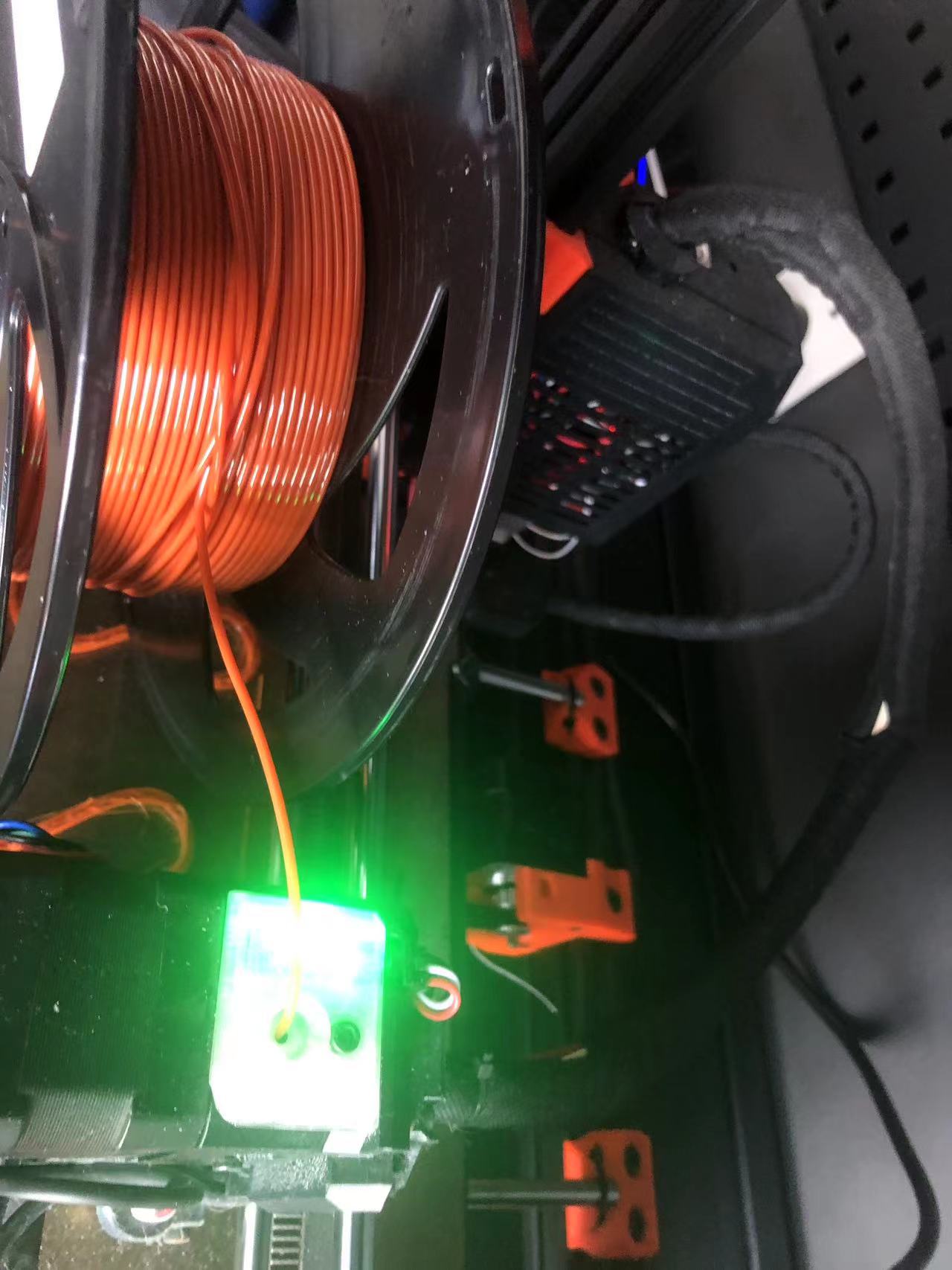
1.Filament Checking:
First, check the filament label, make sure they are dry and organized on the roll, whether the left PETG/PLA on the roll is enough for your project, and whether the setting in the software fits into your filament.
2.PrusaSlicer:Use pursaslicer to turn the STL file into gcode, check whether the machine is consistent, check the printing temperature of the material, set the filling (5-15), and set the skirt.
3.Spray glue on the printing bed:Take out the printing platform and spray glue, just spray a little (the amount of perfume is enough!!! to prevent warping,Only PETG)
4.Check the printing bed:whether the printing bed is clean (to prevent debris on the platform from affecting the balance of the platform and causing printing errors)
5.Set up the printing bed to the right position:Clamp the platform on the two cylinders at the back, and clamp it tightly (be sure to put it well, not on the cylinder!!! It will affect the balance)
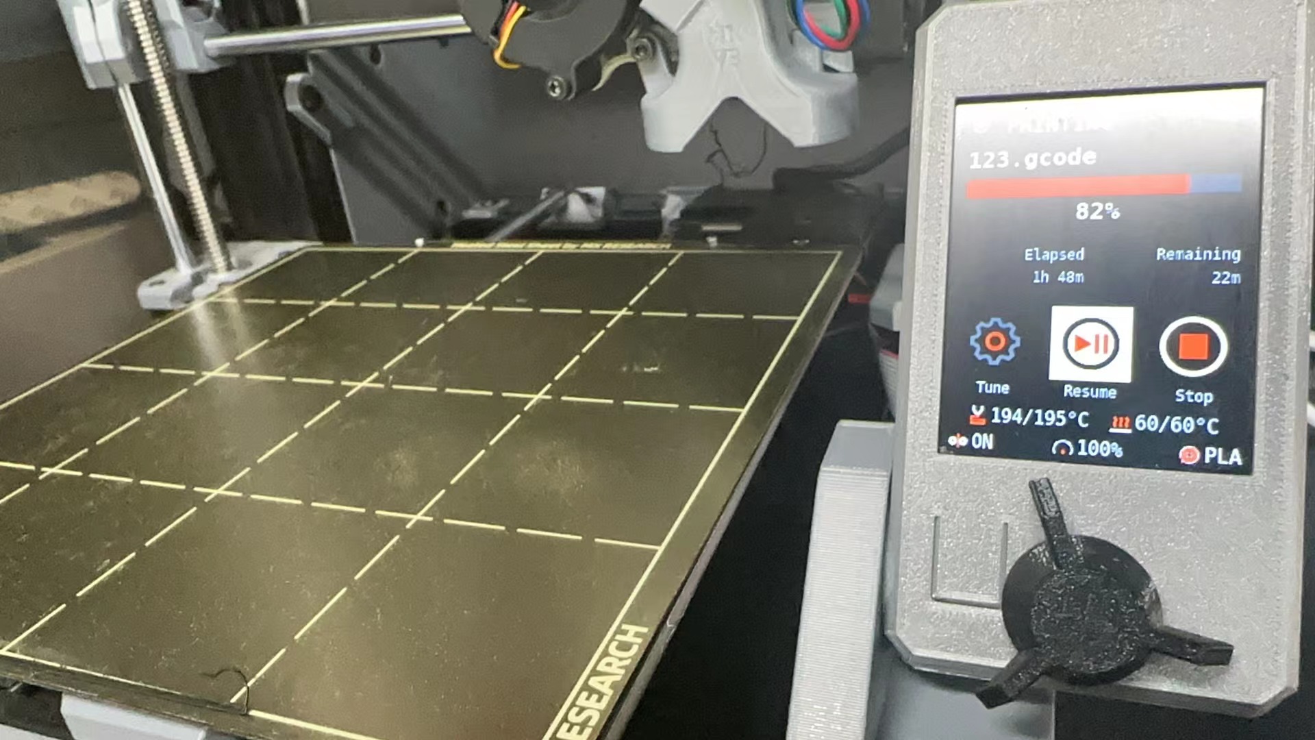
6.Pre-heating:choose the right file, start to print, check the temperature, and take away the waste extruded from the nozzle.
7.Start printing:stay there until the first several layers of printing is finished. if there is an error, check whether there is an error in the above steps, check,and re-print, 90% of the error will not happen if the first layer is running well.
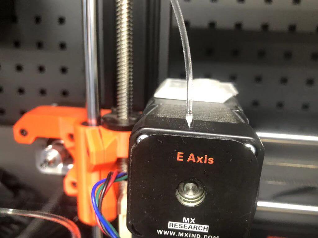
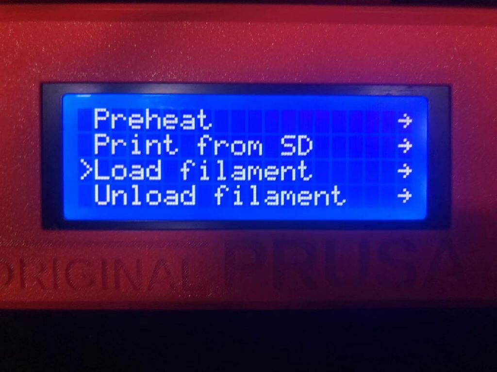
Load/unload filaments for the printer:
1.Press “unload filament”.
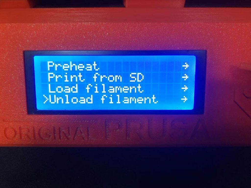
2.The filaments should be appropriately unloaded, you will see the old color of the filaments goes out of the nozzle.
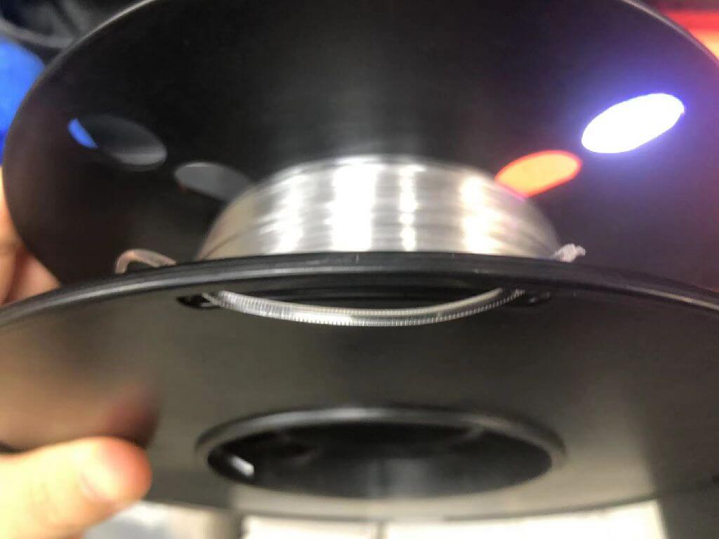
3.Old filament stuck.(Hold on tight, don't let go! ! !)
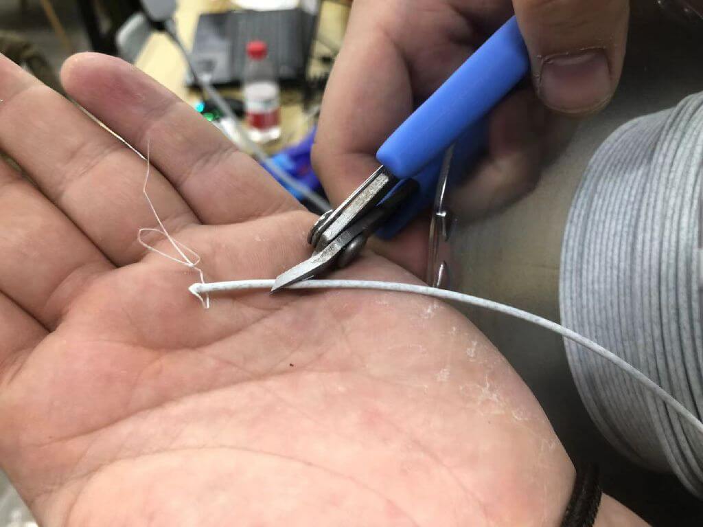
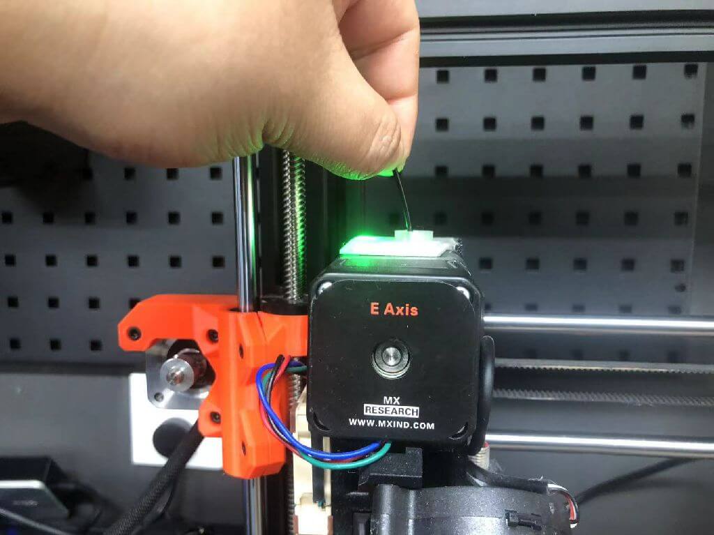
4.Cut filaments: Cut the head of the filament off diagonally, making sure it has a sharp tip.
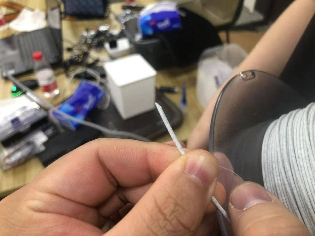
5.Load filaments: push the tip of the filament into the nozzle.
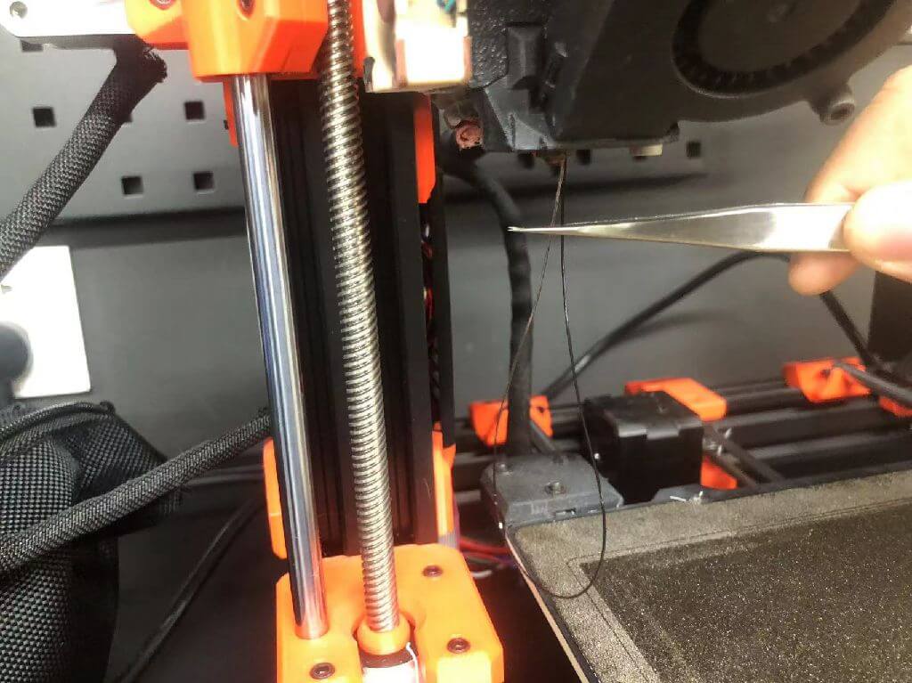
6.Remove waste with tweezers from the hot nozzle.
Filaments features:
1.PLA (PLA-WF)
Advantages:
1.Student-friendly and mostly used in schools.
2.Cheap
3.Non-toxic, easy to print.
4.Low shrinkage rate at low temperature, rarely have edge warping during printing.
Disadvantages:
1.Low intensity, better to use it in decorative parts, not strong enough to be engineering parts.
2.Deterioration by UV exposure.
Setting:
1.Nozzle temperature 190-210.
2.Hot bed temperature 50-60.
3.The fan turns on automatically.
4.Low retraction (no wire drawing, no plugging).
Brand recommendation:
1.olymaker
2.PETG
Advantages:
1.Can be used for engineering parts and structural joints.
2.Relatively non-toxic, very easy to print compared to ABS.
3.Cheap.
Disadvantages:
1.It is difficult for novices to manage the edge warping problem with PETG; PETG will tend to adhere to the more sticky one of the nozzle and the printing bed (when the first layer is applied, make the nozzle closer to the printing bed than usual, and make sure you put some spray glue on the PEI printing bed).
2.Gets wet easily.
3.Make sure the fan is on while printing.
Setting:
1.Nozzle 210-240.
2.Printing bed 70-90.
3.First layer: 220/75.
4.Retraction 2mm or 1mm.
Brand recommendation:
1.PETG-CF
2.GF, mate
3.Fusrock
3.TPU (98A/95A)
Advantages:
1.Non-toxic
2.Less prone to moisture in comparison.
Setting:
1.Retraction should be less than 0.15 - 0.3, speed 25mm/s
2.Stay fan off.
3.If the extruder of the printer is remote type, then it might cause problems while printing with TPU.
4.ABS
Advantages:
1.High strength, special for engineering.
2.High adhesion to the bottom plate.
Disadvantages:
1.Toxic and pungent smell needs strong exhaust.
2.Need to be covered in a box to prevent toxic smoke from leaking out.
4.PEEK
Advantages:
1.Mostly used in the medical field, for example, can be used in printing human teeth, extremely strong.
Setting:
1.400 degrees.
5.PVA
Advantages:
Soluble in water, and can be used to print support parts.
Key Settings in slicer:
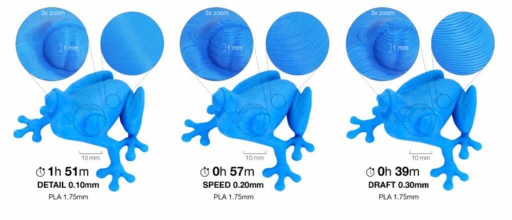
1.Layer height
Height of the individual slices/thickness of each layer. Layer height is the main factor affecting both:
1.print time
2.vertical resolution
By choosing taller layer heights you can significantly shorten the print time at the cost of more visible layers. On the other hand, choosing a small layer height (e.g. 0.10 mm) will result in extra detail at the cost of longer print times.
Generally, we do not suggest going lower than 0.10 mm as the improvement in print quality with 0.07 or 0.05 mm layers is relatively minor with significantly longer print times.
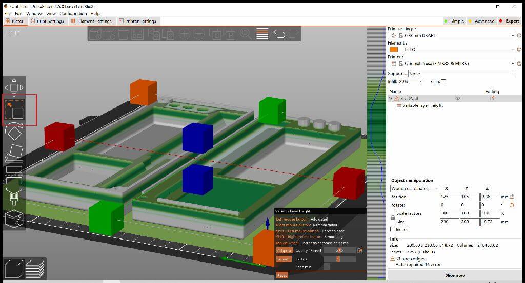
Precautions
1.Keep in mind, that layer height changes only the vertical resolution. For example, an embossed text parallel with the print bed will look the same regardless of the layer height. If you’re looking for increased resolution in the XY plane, check nozzles with a different diameter.
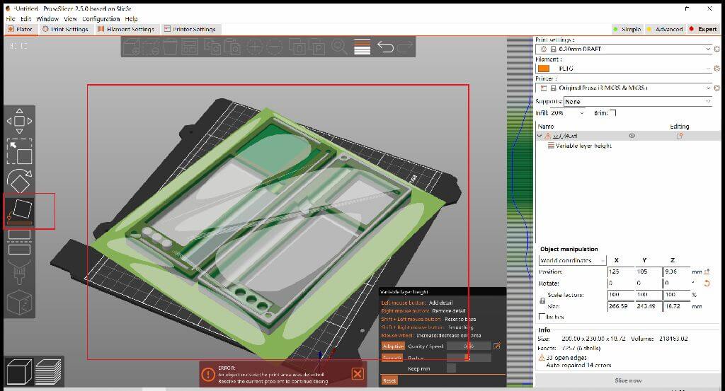
2.To get the best of both worlds, consider using the Variable layer height function.
3.Maximum layer height for your nozzle layer height should be below 80% of the nozzle diameter (e.g. the maximum layer height with a 0.4 mm nozzle is about 0.32 mm). The layer height cannot be higher than the nozzle diameter, PrusaSlicer will display an error message if you try to input such a value.
2.Perimeters
Defines the minimum number of outlines that form the wall of a model. Original Prusa profiles always use a minimum of two perimeters.
Precautions
1.Increasing model strengthThe strength of a model is mostly defined by the number of perimeters (not the infill). If you want to have a stronger print, increase the number of perimeters.
2.Also depends on the size of your hot melt copper nut
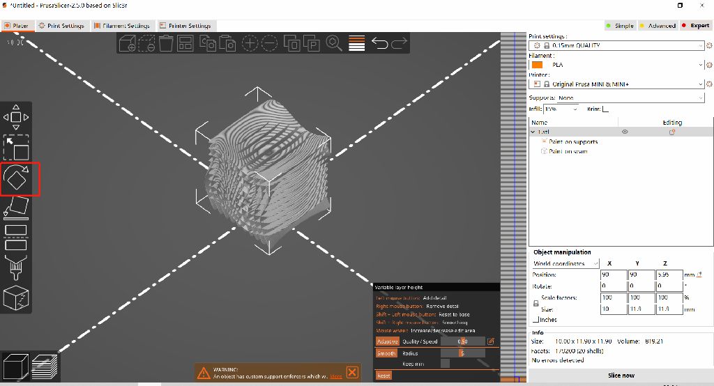
3.Fuzzy skin
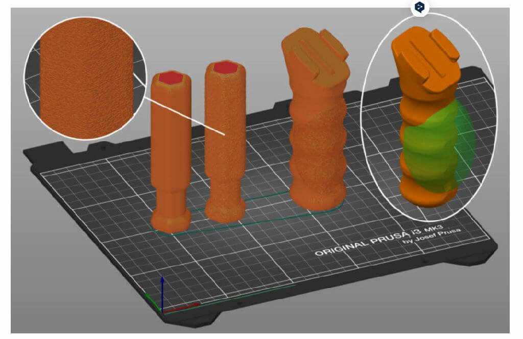
1.The Fuzzy skin feature lets you create a rough fiber-like texture on the sides of your models. If enabled, the perimeter will be resampled with a random step size and each new sample point will be shifted inside or outside of the perimeter by a random length limited by the Fuzzy skin thickness. This simple algorithm produces surprisingly nice results suitable for tool handles or just to give the print surface a new interesting look or to hide print imprecisions. You can also use modifiers to apply fuzzy skin only to a portion of your model.
2.You'll find Fuzzy skin settings in Print settings - Layers and perimeters.
Precautions
1.Fuzzy skin is only available in PrusaSlicer 2.4 and newer versions.
2.Some options will not appear when PrusaSlicer is in Simple mode.
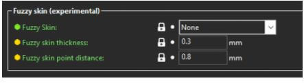
Fuzzy skin type
1.You can select to apply Fuzzy skin only to External perimeters or to All perimeters.
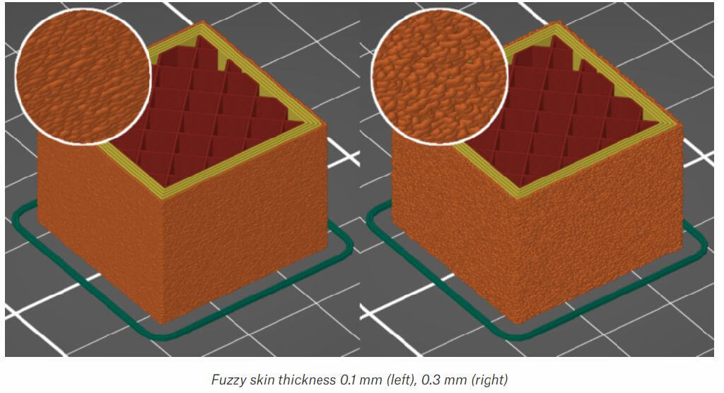
2.The maximum distance that each skin point can be offset (both ways) is measured perpendicular to the perimeter wall.
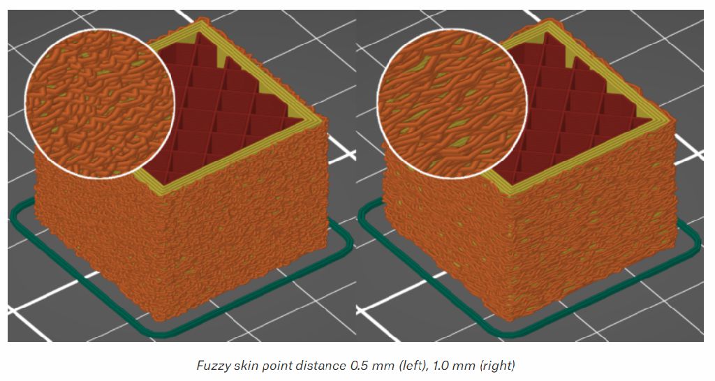
Fuzzy skin point distance
1.Perimeters will be split into multiple segments by inserting Fuzzy skin points. Lowering the Fuzzy skin point distance will increase the number of randomly offset points on the perimeter wall.
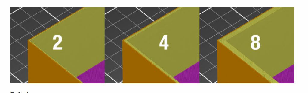
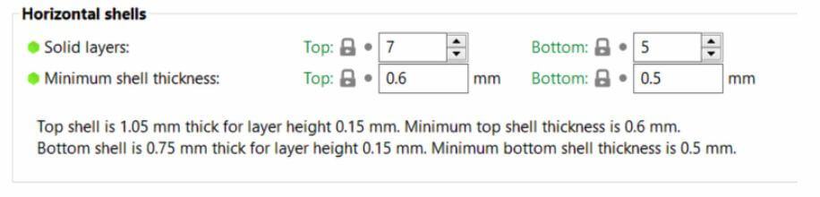
4.Solid layers - top/bottom
1.The bottom and top part of each model is usually filled with solid layers (100% infill).
2.You can set how many top and bottom layers you wish to print. You can also set a minimum wall thickness, which is especially useful when using the variable layer height function. The tooltip below these settings will update with every change you make, giving you a better idea of the resulting top/bottom wall thickness.
3.Setting the top or bottom solid layers to 0 overrides the minimum wall thickness. So you don't have to set the minimum wall thickness to 0 as well in order to get top or bottom layers.
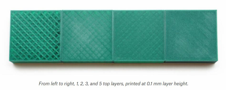
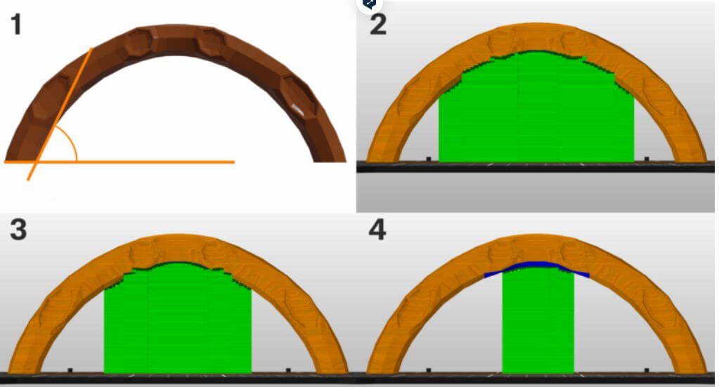
4.The top solid infill is essentially bridging over the infill pattern. Because of that, you’ll almost always see a little bit of sag of the first few solid infill lines. The lower the infill, the longer the bridging distance, and as a result the bigger the sag. This can be counteracted by simply increasing the number of solid layers - we suggest at least 3 top layers. You can further reduce this behavior with a modifier mesh, which increases the infill for the last few layers before the solid infill.
Precautions
1.Keep in mind that when you’re printing at low layer heights, you will need more solid layers to achieve the same top/bottom wall thickness (e.g. with 0.3 mm layer height use 3 top layers, with 0.1 mm layer height use 9 top layers).
5.Fill density
1.Most models can be printed with 10-15% infill. If the top of the model closes gradually, it can be printed hollow (0% infill), though we generally do not recommend it. If you need the model to be heavier, want more compression resistance or higher stiffness, you can increase the infill. You'll rarely need infill higher than 30%. Finally, you can print the model with 100% infill and the infill pattern will be forced to rectilinear. Keep in mind that 100% infill can have a negative impact on the look of the printed object.
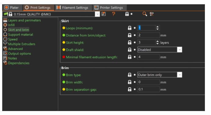
6.Skirt
1.The skirt is a printed outline of all of the models on the print bed. It's printed before any of the models and its purpose is mainly to stabilize the flow of the filament through the nozzle.
2.The skirt is also useful to verify the adhesion of the first layer to the print bed. Since it's printed before the models, you can quickly change the Live Z adjust if you see the first layer not sticking properly or being too squished by the nozzle.
7.Support matarial
1.3D printers work by laying layer over layer of plastic to create a 3D object. Each new layer must be supported by the one beneath it. If part of your model starts in mid-air and is not supported by anything below, you need to add an additional support structure to ensure a successful print.
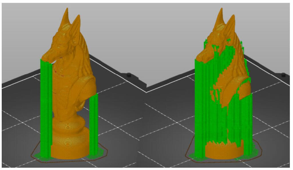
8.Overhang threshold
1.The Overhang threshold value represents the most horizontal slope (measured from the horizontal plane) that you can print without support material (90=vertical).
2.Changing this value is a quick way to adjust the amount of generated supports.The lower the value, the less support will be generated.
9.Raft layers
1.The object will be raised by this number of layers and support material will be generated under it. When the print finishes, you can grab the raft and peel it away from the part.
Individual assignments:
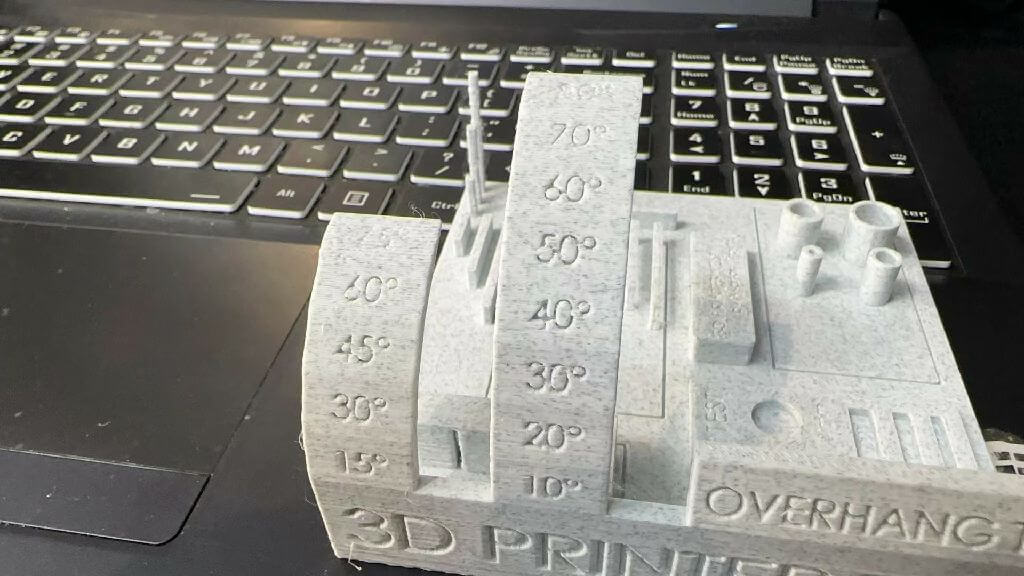
(nozzle temperature 195, bed 60, speed 100, material PLA, filling 15%, time 6h45m)
Drape performance test
Measure the overhang structure at 30, 45, 60, and 70 degrees to see if there are any drooping wire edges, shaking during extrusion, and overflowing plastic filaments.
There is no obvious sag, and every angle is perfectly pressed up.
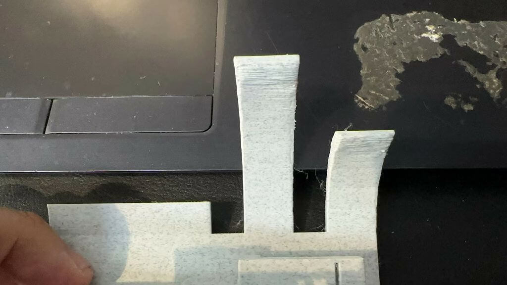
Bridge Performance Test
Check the five bridges for edge wire hanging or dangling plastic wire. There is no noticeable sag and each length is perfectly attached.
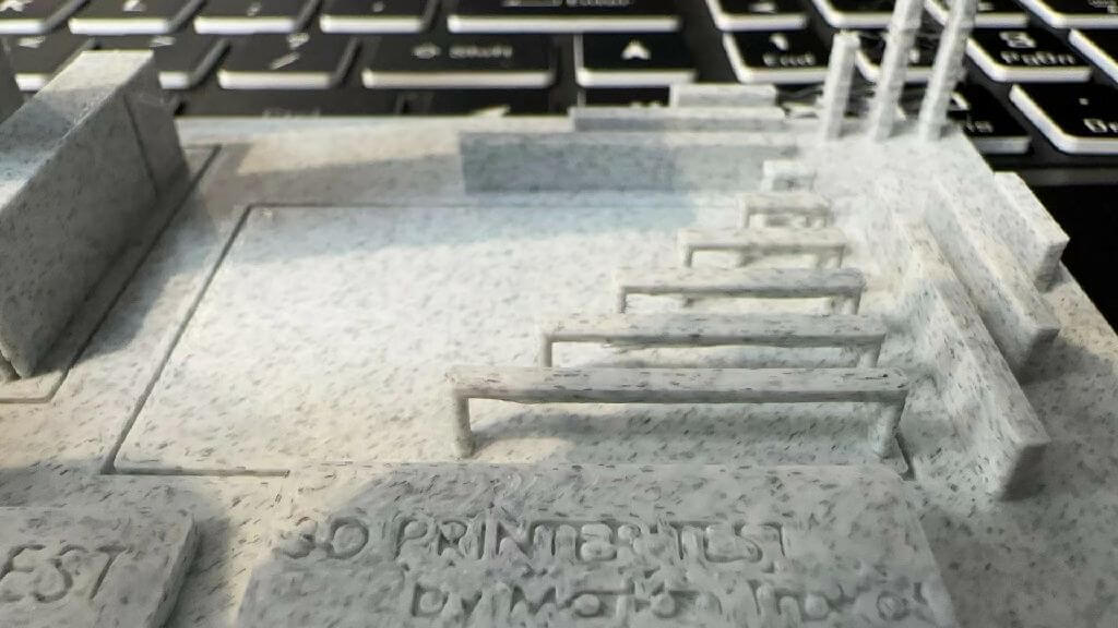
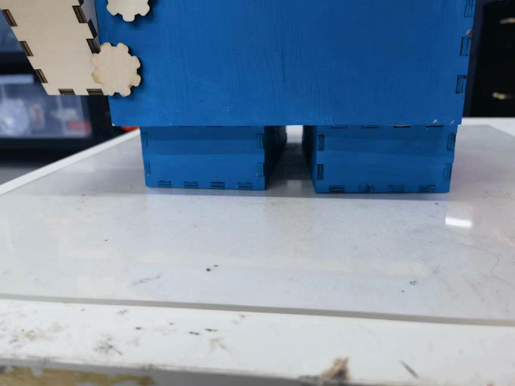
support test
-
The slight gap in the support is nice, but seems too tight to remove easily.
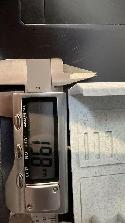
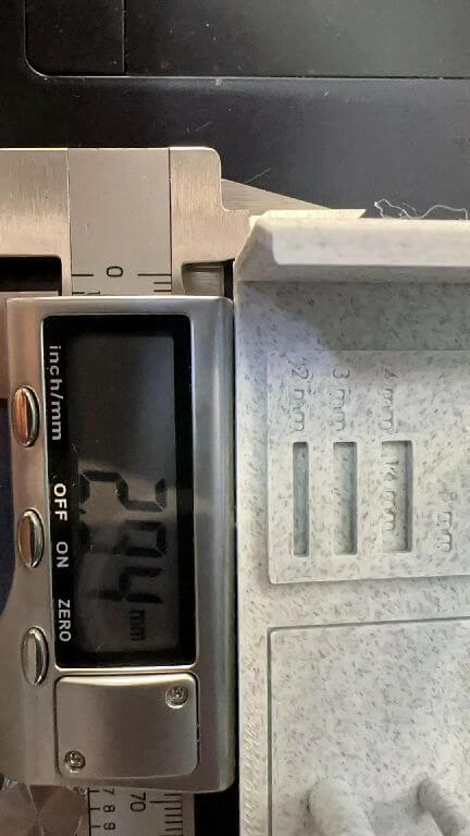
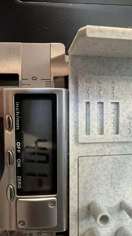
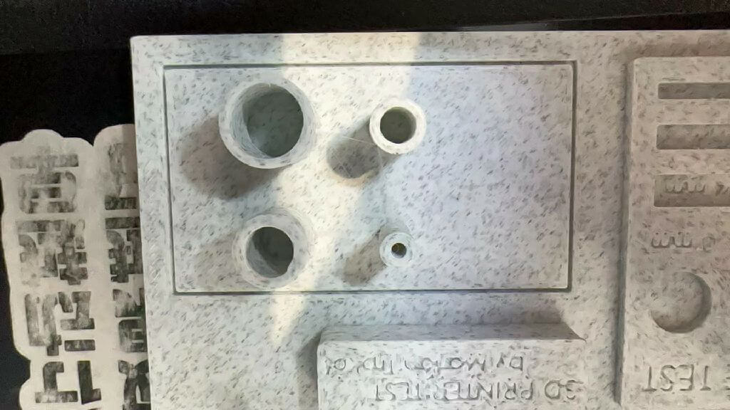
precision test
It is very accurate in non-industrial machines, and the error is less than 0.05-0.01mm.
Design drawing size:2mmx14 Actual size:1.98mmx13.95
Design drawing size:3mmx14 Actual size:2.94mmx13.93
Design drawing size:2mmx14 Actual size:4.01mmx14.01
pipeline test
prints well
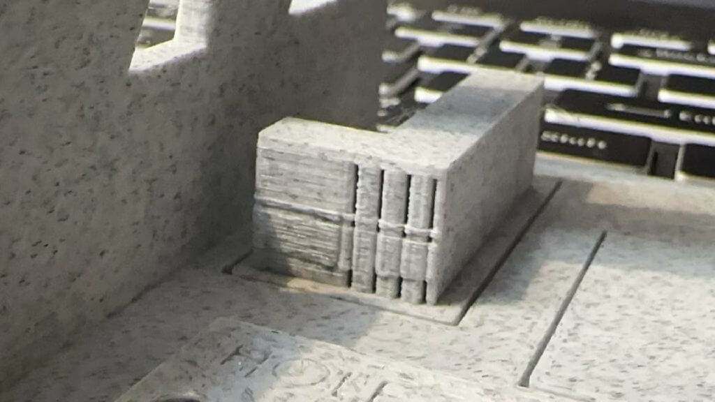
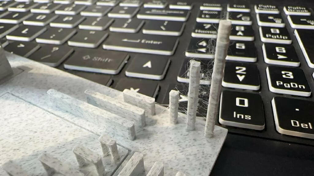
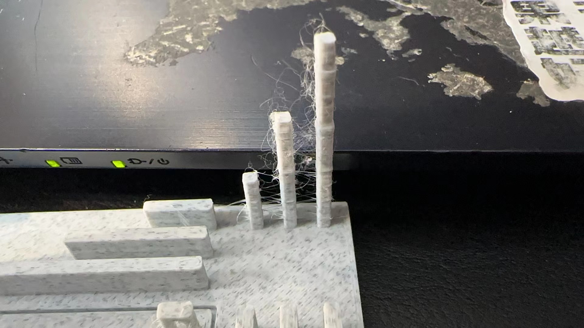
pillar test
There are some problems: 1. The material is wet 2.Significant buildup of material on long columns.
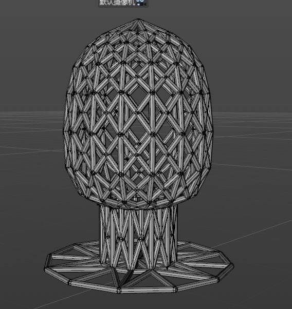
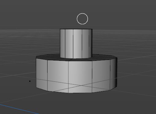
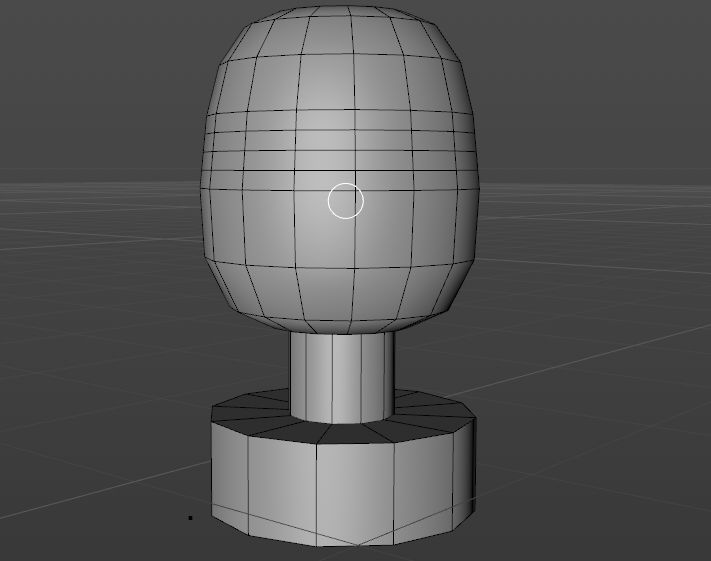
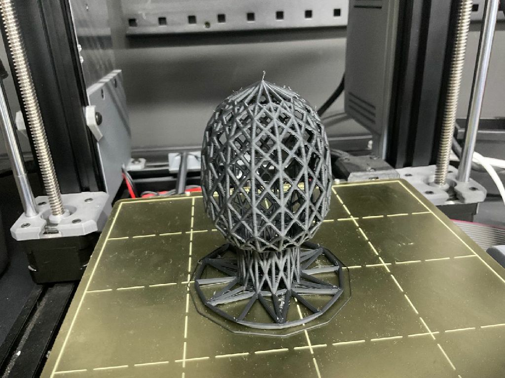
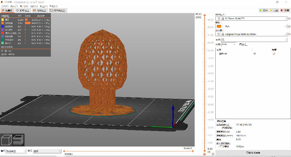
3D Model Making
Multiple channels are interspersed in one object, which cannot be achieved by material reduction.
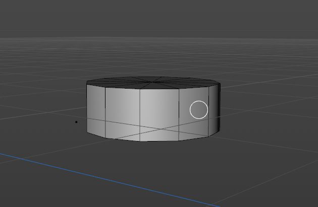
Model 1: Exclude
(reason is in problem item)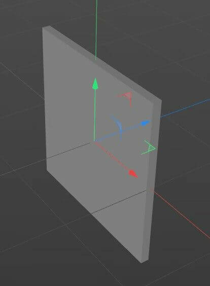
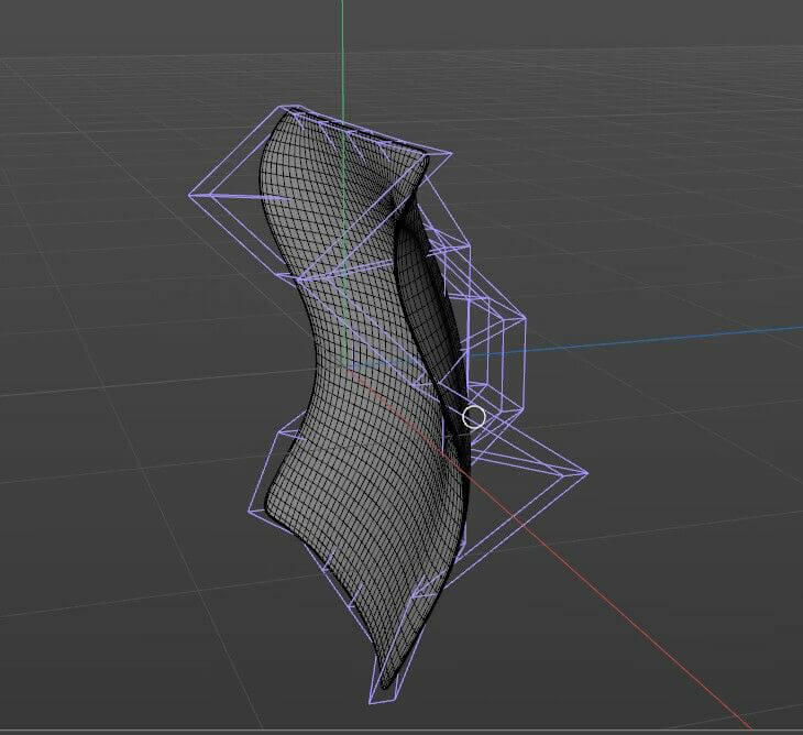
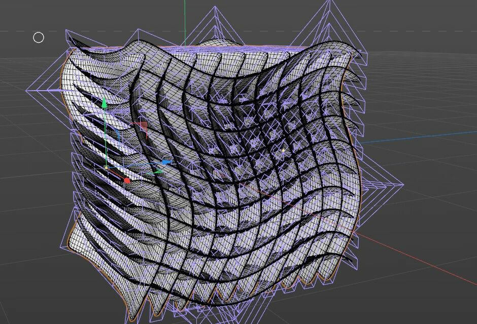
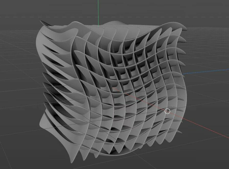
Model 2: Using
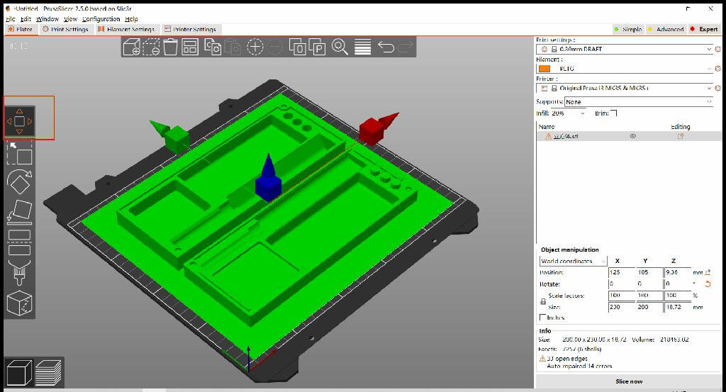
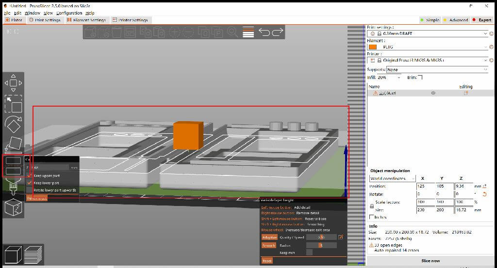
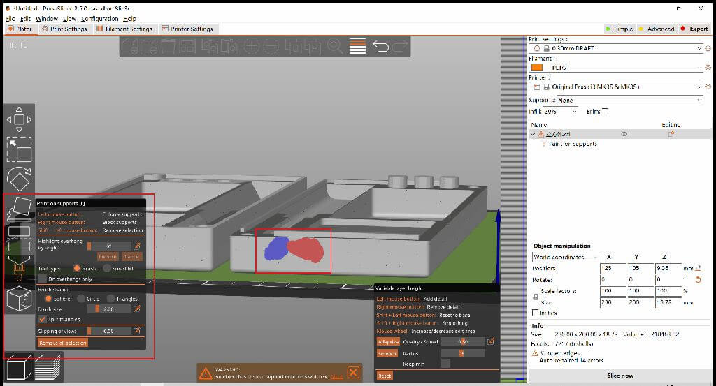
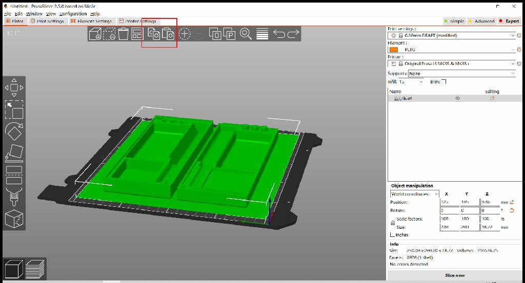
Prusa Slicer
1.move 2.scale 3.rotate 4.cut 5.arrange 6.copy 7.paste 8.place on face 9.paint-on supports 10.variable lauer height

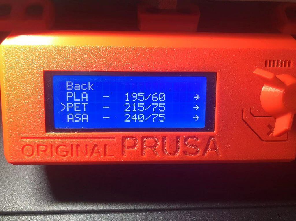
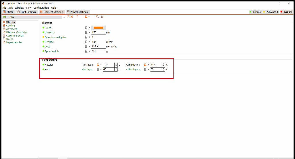
Print temperature setting
PVA(personal use):Nozzle First Layer 195 Other Layers 195
PVA(personal use):Bed First Layer 60 Other Layers 60
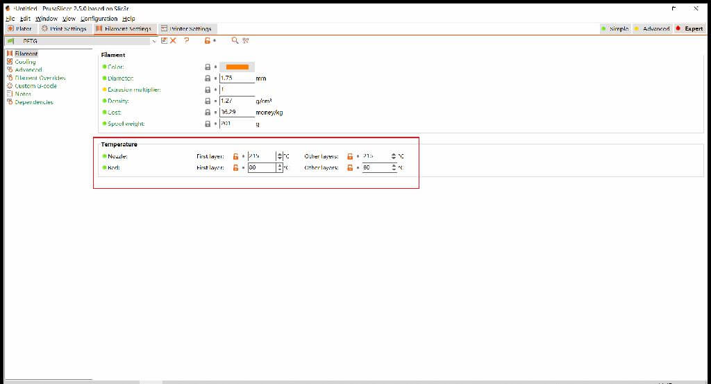
PETG(personal use):Nozzle First Layer 215 Other Layers 215
PETG(personal use):Bed First Layer 75 Other Layers 75
Print Settings
Print settings:
0.20mm QUALITY
Filament:
Generic PETG
Printer:
Original prusa i3 MK3S & MK3S+
Supports:
None
Infill:
15%
If the model is wrong, please click in front of the model ! repair
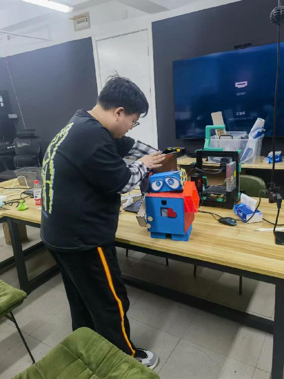
3D scan an object
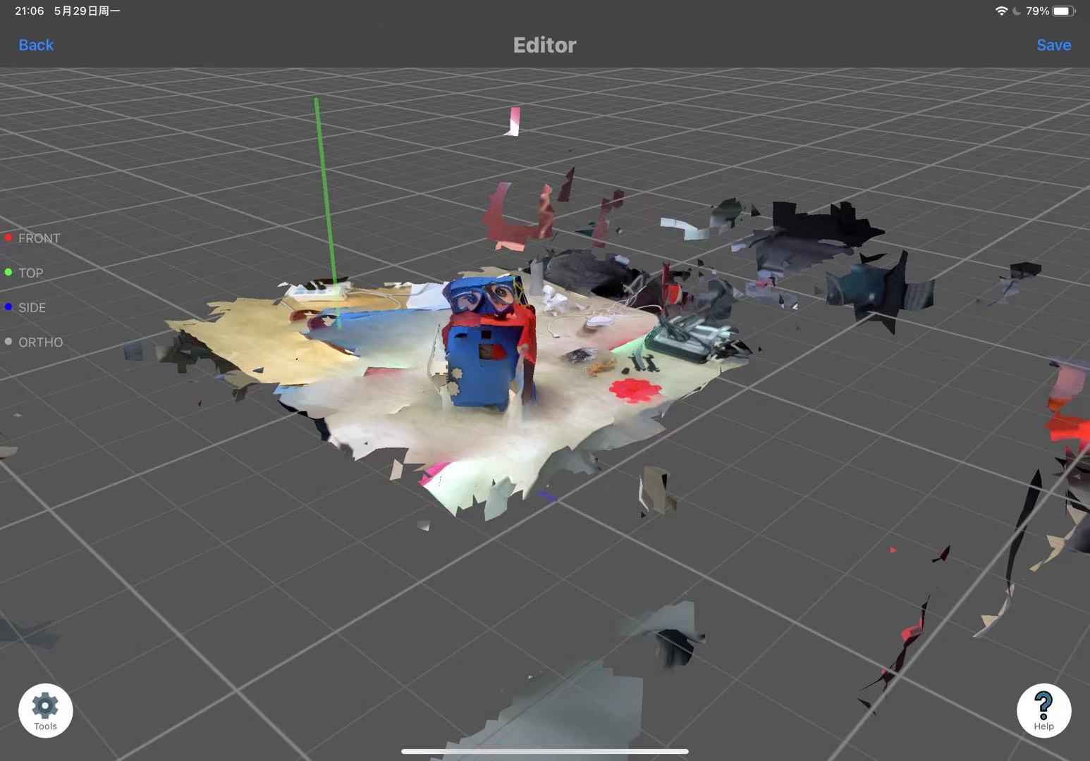
3D scanning tool:3D Scanning APP in Ipad
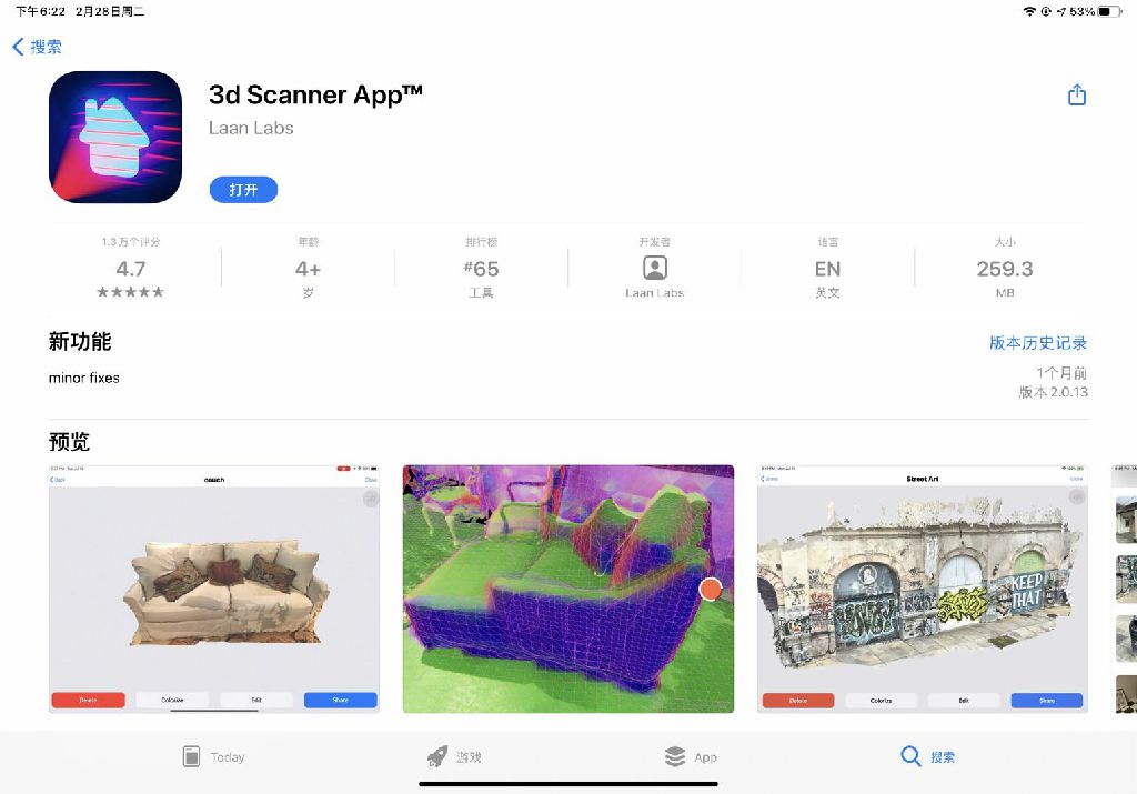
Scanning process
Then all I need to do is walk around the subject and take shots from different angles, just as simple as shooting a video with a mobile phone.
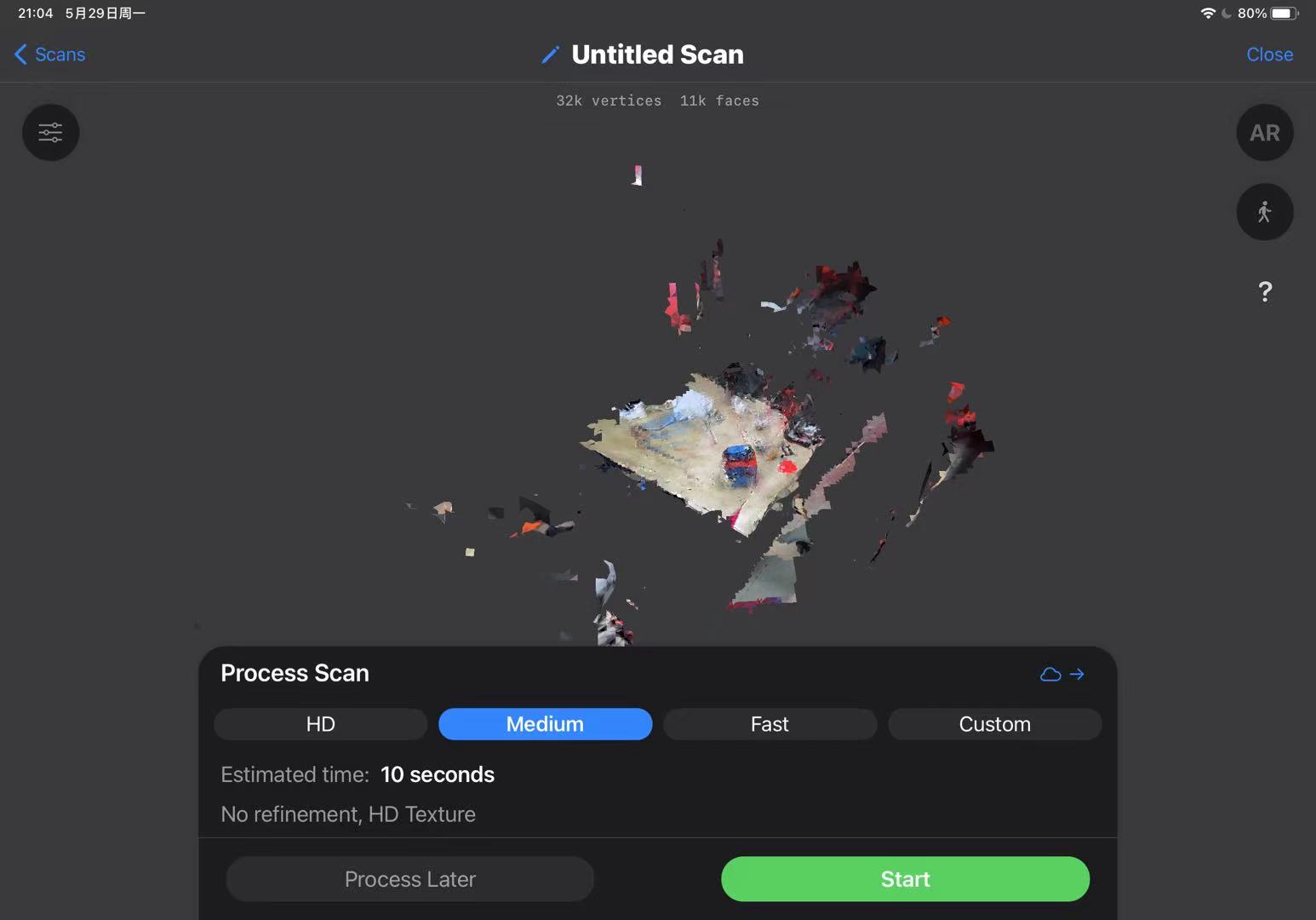
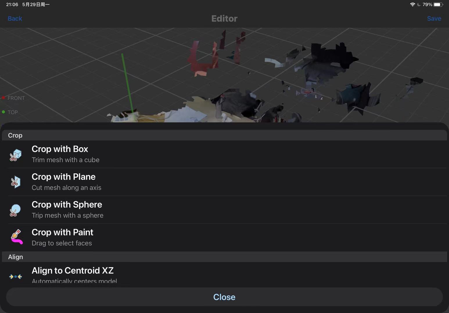
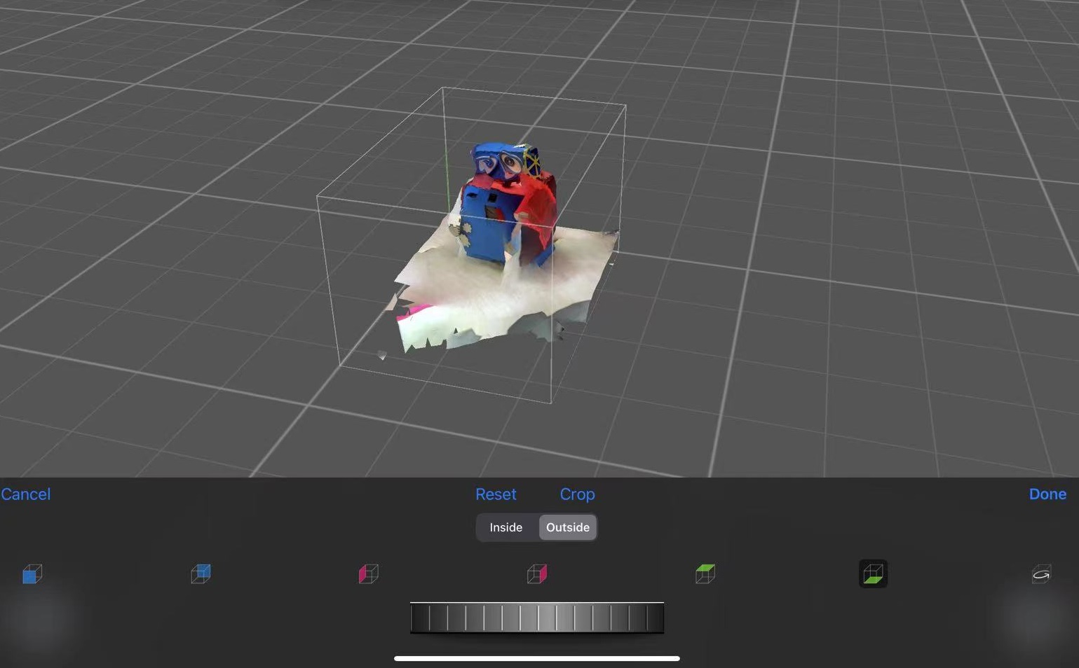
This application also allows for basic editing of the scanned model. Just click on 'Tools,' select the cropping mode, and you can enter the editing interface to crop any excess parts.
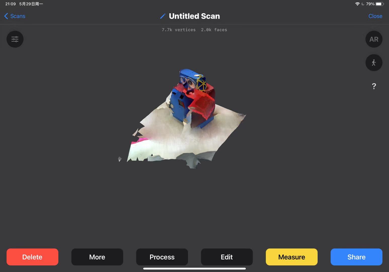
Click 'Share' to export the model.
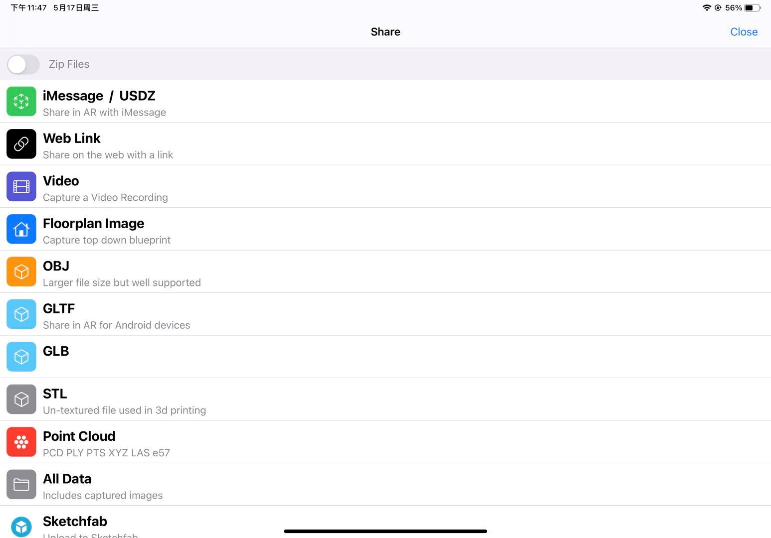
It requires a LIDAR camera sensor device. The 3d scans can be exported in popular formats such as OBJ, GLTF, STL, etc. Also export the model as a raw point cloud in formats: PTS, PCD, PLY, XYZ, ect.
1. Scanning should be carried out in an open field.
2. Smoothly rotate 360 degrees around an object (don't forget the top of the person's head), ensuring full scan.
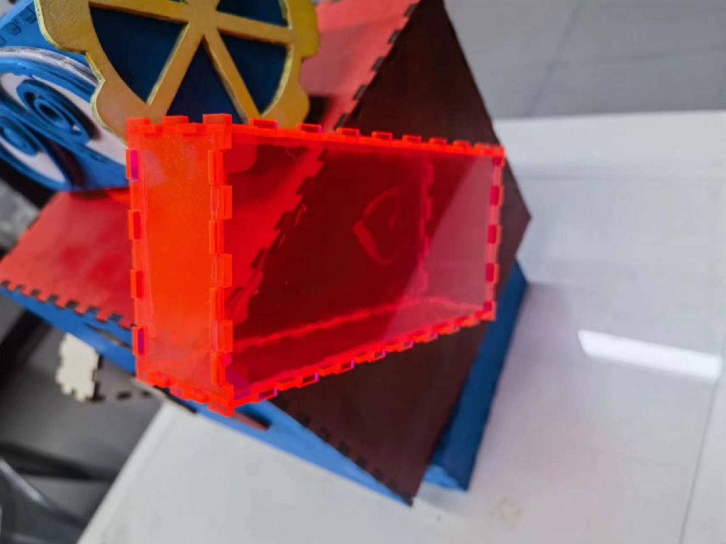
3. The scanning effect of transparent materials such as acrylic is not good.
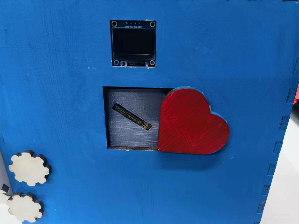
4. Small bumps cannot be scanned (probably due to machine reasons)。
5. The bottom is not easy to scan.
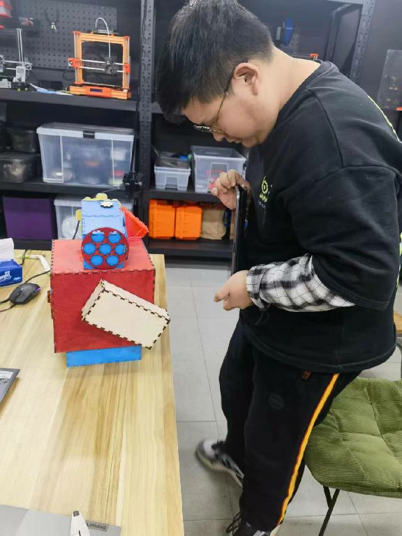
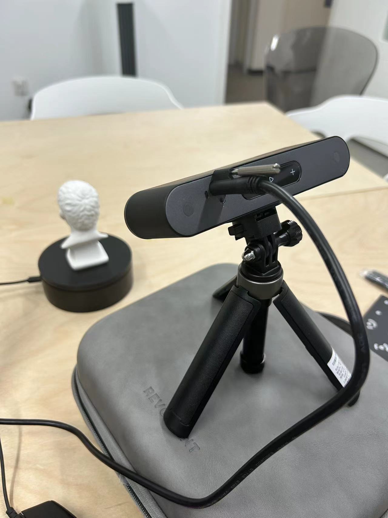
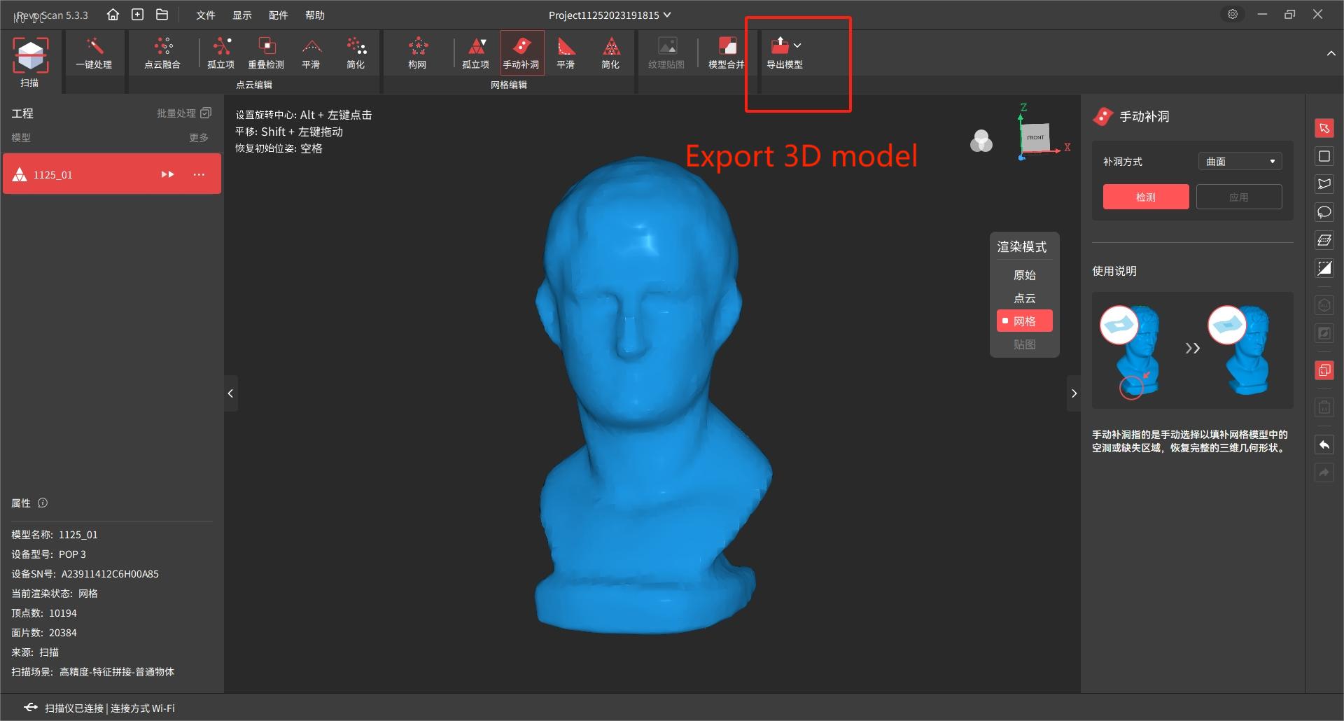
3D scanning tool:POP 3 + Revo Scan 5
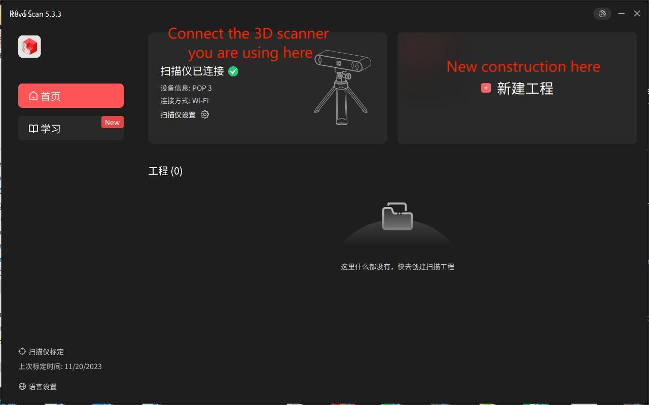
1.Connect the POP 3 to your computer, turn on the turntable in the POP 3 kit, and aim the POP 3 at the object you want to scan.
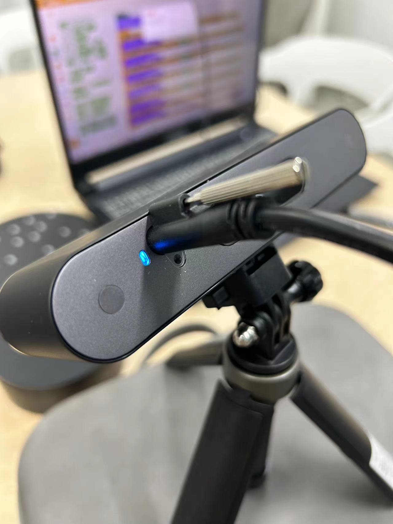
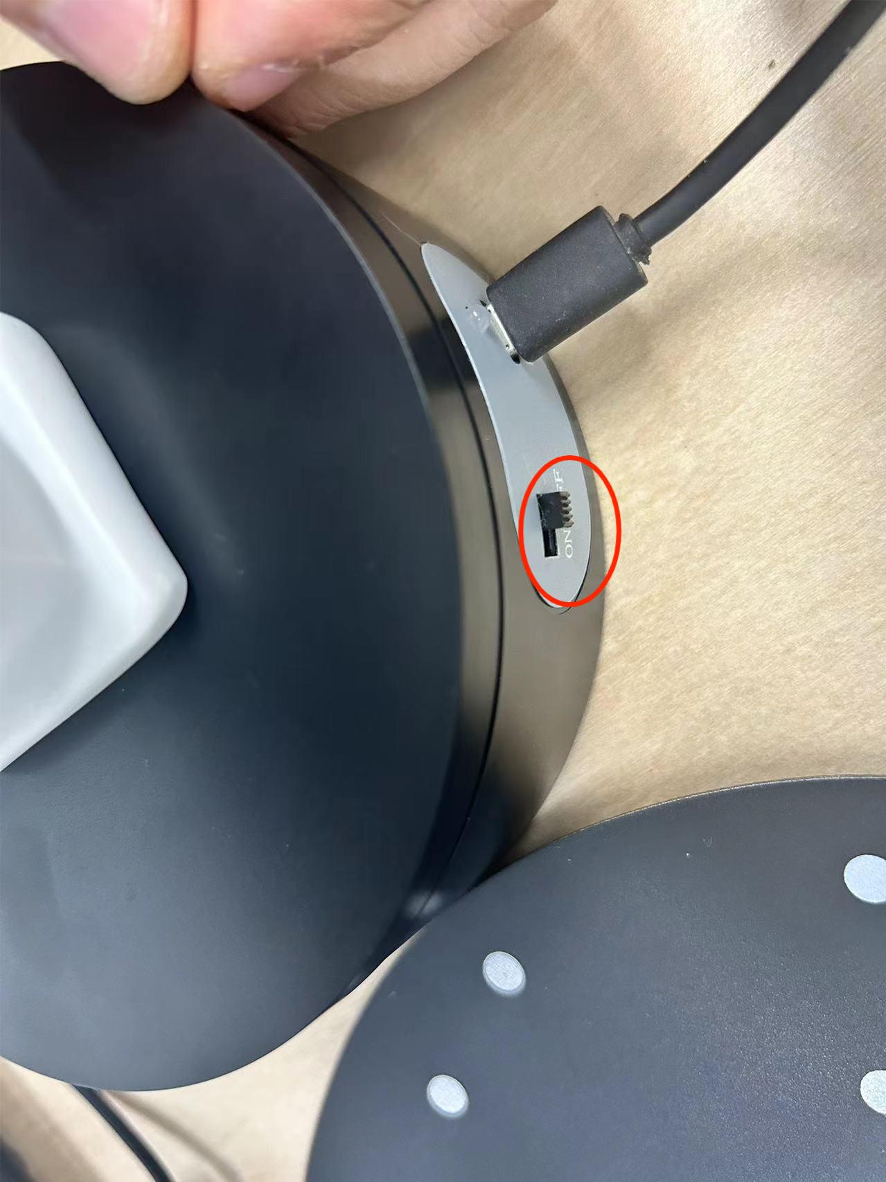
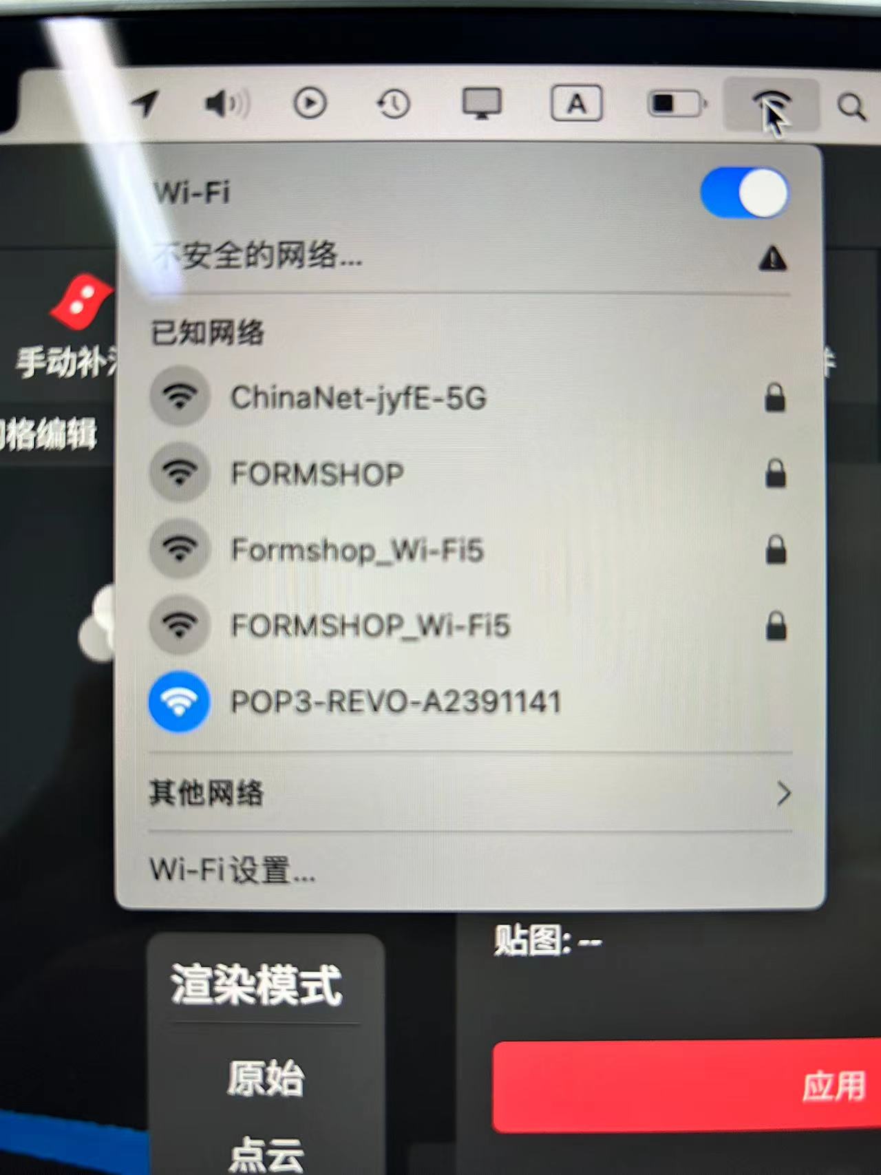
2.Select POP3-REVO-A2391141 in your computer's network connection to connect to your own POP 3.
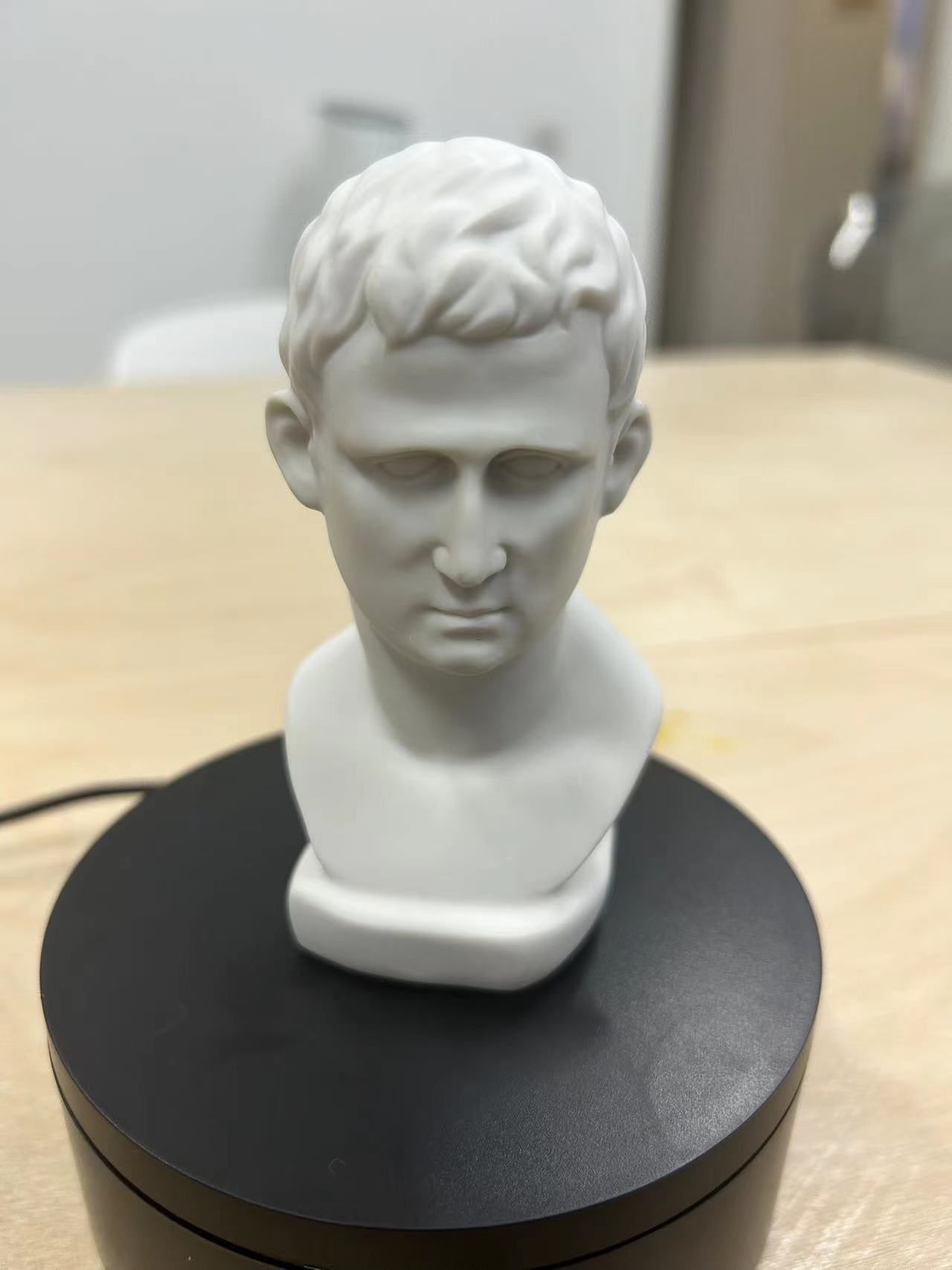
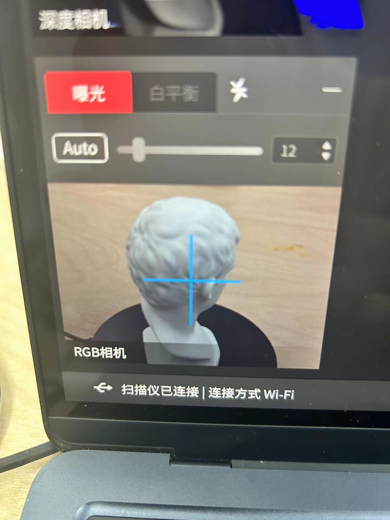
3.Place the object you want to scan on the turntable in the POP 3 kit and point the camera at the object you want to scan. The image returned by the camera will be displayed in Revo Scan 5.
4.Click New Project.
5.Click to start
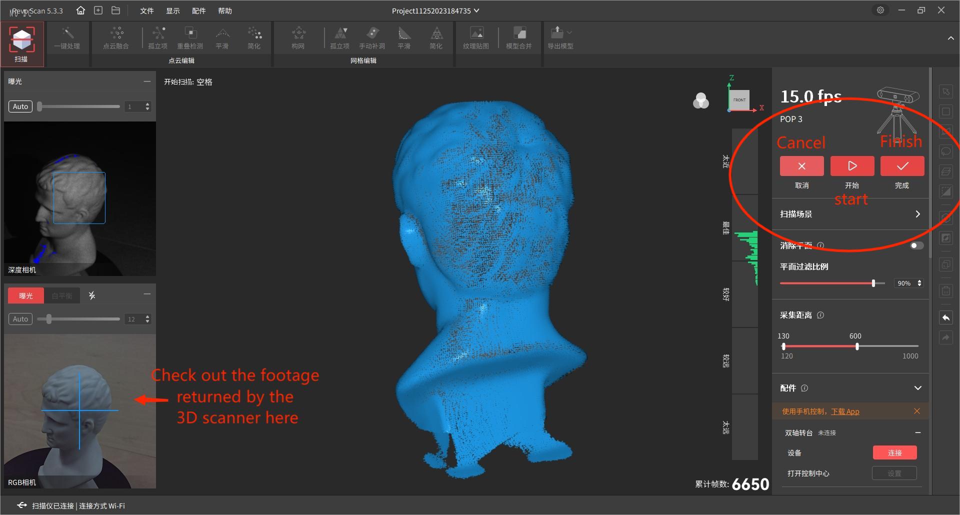
6.You have to wait for the turntable to rotate three times before stopping, otherwise the model accuracy will be low because the number of scans is too low.
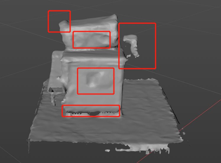
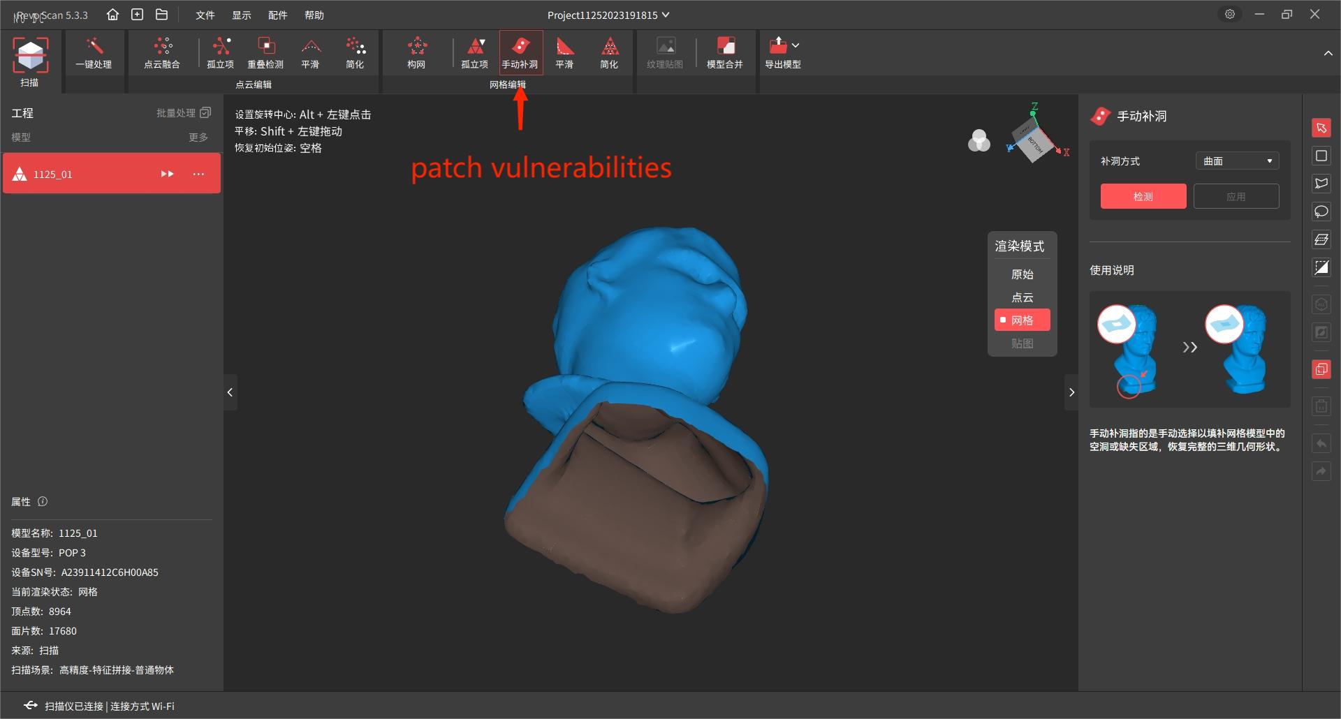
7. After you stop scanning, you will notice that there are Arrancars in the model.
7.1 For the Arrancar on the top of the object, you can perform 2 scans by raising the POP 3.
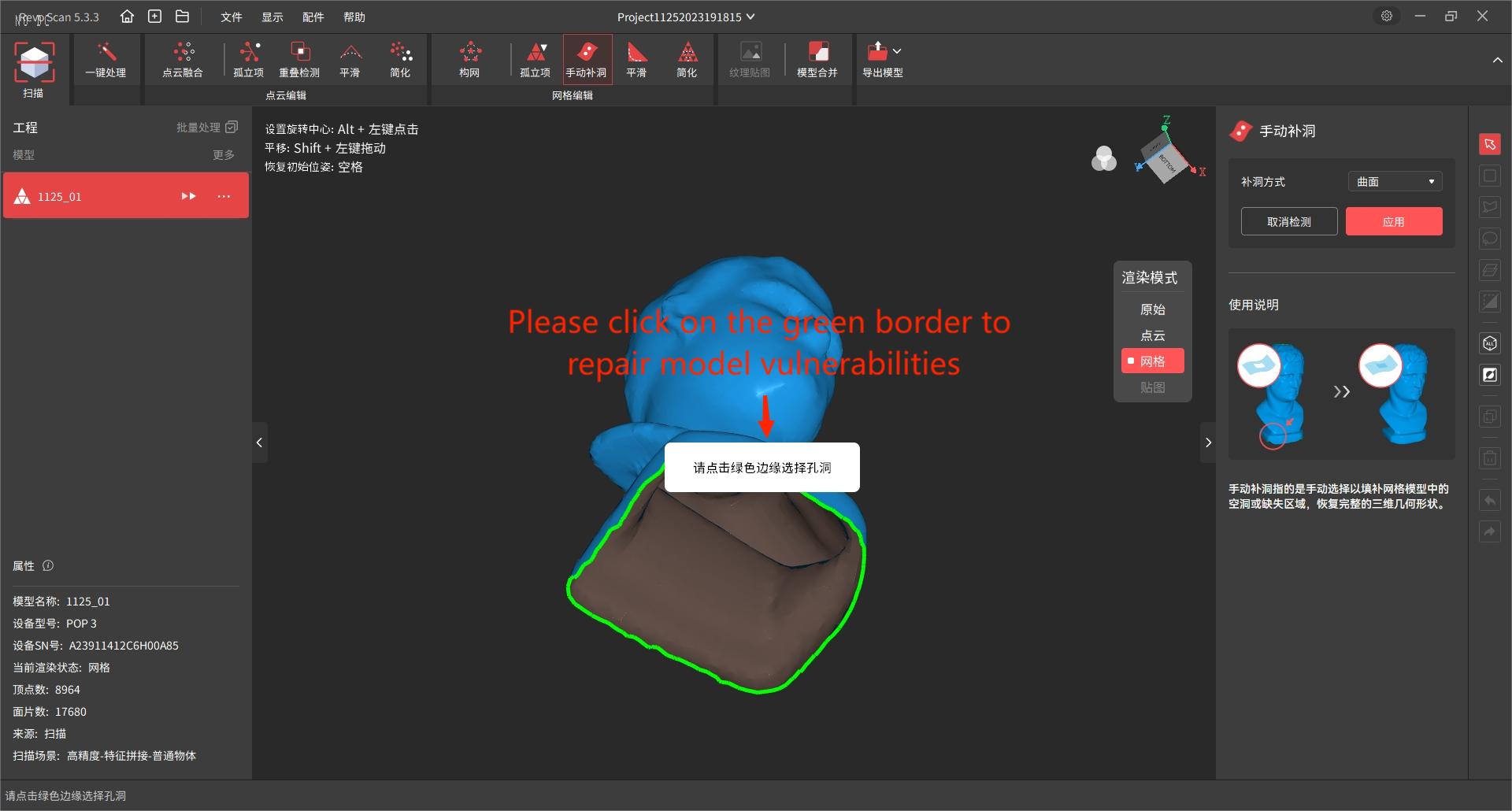
7.2 You can repair the broken surface at the bottom of the object by using the Manual repair of broken surface tool.
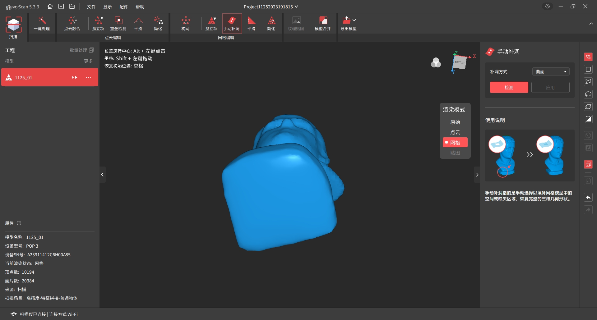
8. Export model
Downlod Links
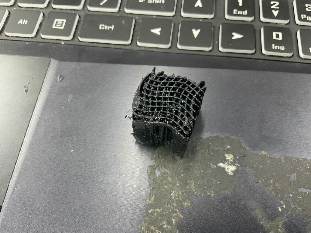
3D scanned documentsError encountered
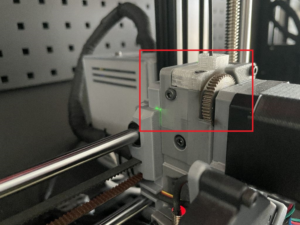
1.wire stuck
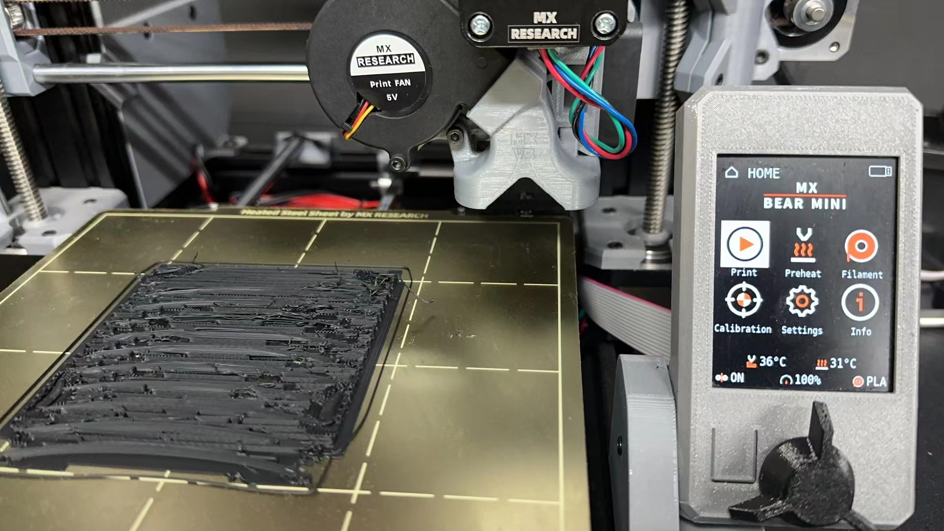
2.Nozzle clogged
3.material wet
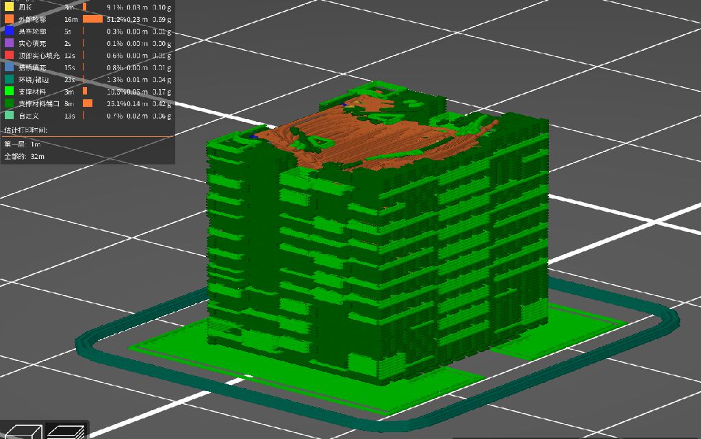
4. Models lack design
Too many supports to remove.
problem solving
1.wire stuck
Lock material when changing material
2.Nozzle clogged
1.It's not that the nozzle is blocked, but that the material pushing port is too tight, the material is smooth, and the material pushing port is a little loose.
2. The temperature of the air conditioner affects the room temperature and affects the heat dissipation of the fan. If the temperature is too high, the material will soften.
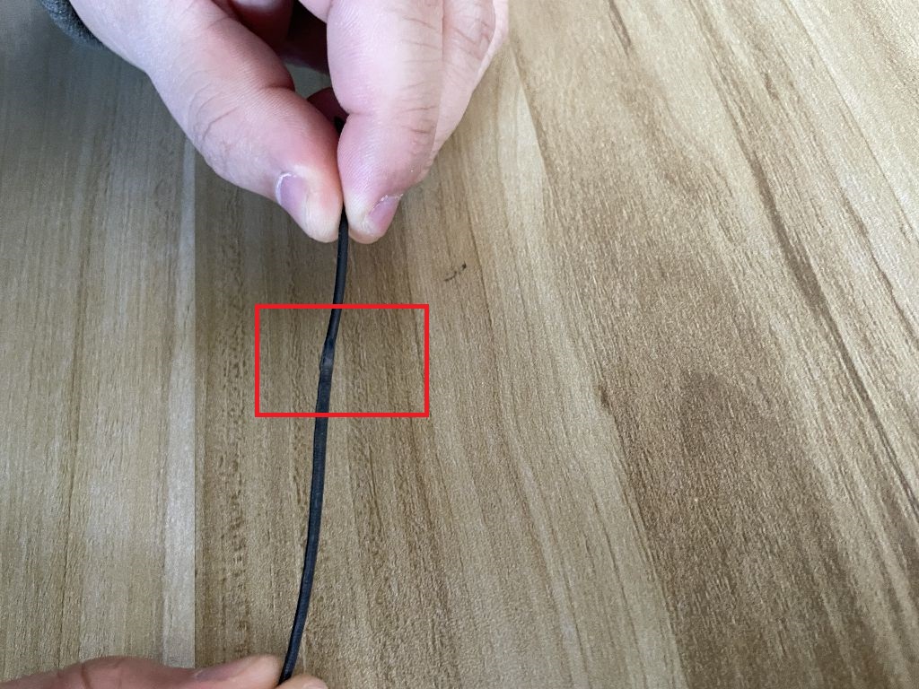
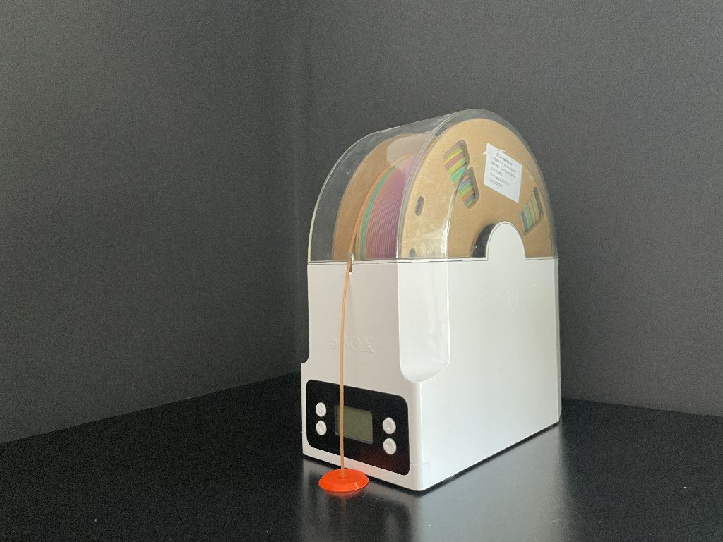
3.material wet
Store it in an airtight box and put it in the dryer for 1 hour before printing (70% recovery).
4. Models lack design
1. Remake the model to ensure that each angle is 45 degrees. 45 degrees can ensure that the model is printed with the least support.