Networking and Communications
Assignment
- Group Assignment:
- Send a message between two projects.
- Document your work to the group work page and reflect on your individual page what you learned.
- Individual Assignment:
- design, build, and connect wired or wireless node(s) with network or bus addresses.
Evaluation Standards
- Linked to the group assignment page.
- Documented your project and what you have learned from implementing networking and/or communication protocols.
- Explained the programming process(es) you used.
- Outlined problems and how you fixed them.
- Included design files (or linked to where they are located if you are using a board you have designed and fabricated earlier) and original code.
- Included original design files and source code.
- Included a 'hero shot' of your network and/or communications setup.
Output Preview

Group Assignment
I2C communication
I2C is a serial communication protocol, so data is transferred bit by
bit along a single wire. You can know more about it from this great SparkFun
tutorial
We used I2C protocol to connect between Xaio RP2040 board (Master) and Arduino UNO
(Slave)
I2C Code
Master
#include <Wire.h>

void setup() {
  Wire.begin();
}

void loop() {
  Wire.beginTransmission(8);
  Wire.write('O');
  Wire.endTransmission();
  delay(1000);
  Wire.beginTransmission(8);
  Wire.write('S');
  Wire.endTransmission();
  delay(1000);
}
Slave
#include <Wire.h>

void setup() {
  Wire.begin(8);
  Wire.onReceive(receiveEvent);
  Serial.begin(9600);
}

void loop() {
  delay(100);
}

void receiveEvent(int howMany) {
  while (1 < Wire.available()) {
    char c = Wire.read();
    Serial.print(String(c));
  }
  char x = Wire.read();
  Serial.println(String(x));
}
Check our
Group assignment page to see more of our assignment.
Networking
Wireless
I wanted to try out the NodeMCU ESP8266 dev. board. So, I followed this detailed
tutorial for how to host a simple Web Server using ESP8266 to control 2 LEDs.
Web Server Code
// Load Wi-Fi library
#include <ESP8266WiFi.h>
// Replace with your network credentials
const char* ssid = "WIFI_Name";
const char* password = "WIFI_Password";
// Set web server port number to 80
WiFiServer server(80);
// Variable to store the HTTP request
String header;
// Auxiliary variables to store the current output state
String outputD2State = "off";
String outputD3State = "off";
// Assign output variables to GPIO pins
const int outputD2 = 4;
const int outputD3 = 0;
// Current time
unsigned long currentTime = millis();
// Previous time
unsigned long previousTime = 0;
// Define timeout time in milliseconds (example: 2000ms = 2s)
const long timeoutTime = 2000;
void setup() {
  Serial.begin(115200);
  // Initialize the output variables as outputs
  pinMode(outputD2, OUTPUT);
  pinMode(outputD3, OUTPUT);
  // Set outputs to LOW
  digitalWrite(outputD2, LOW);
  digitalWrite(outputD3, LOW);
  // Connect to Wi-Fi network with SSID and password
  Serial.print("Connecting to ");
  Serial.println(ssid);
  WiFi.begin(ssid, password);
  while (WiFi.status() != WL_CONNECTED) {
    delay(500);
    Serial.print(".");
  }
  // Print local IP address and start web server
  Serial.println("");
  Serial.println("WiFi connected.");
  Serial.println("IP address: ");
  Serial.println(WiFi.localIP());
  server.begin();
}
void loop(){
  WiFiClient client = server.available();   // Listen for incoming clients
  if (client) {                             // If a new client connects,
    currentTime = millis();
    previousTime = currentTime;
    Serial.println("New Client.");          // print a message out in the serial port
    String currentLine = "";                // make a String to hold incoming data from the client
    while (client.connected() && currentTime - previousTime <= timeoutTime) {  // loop while the client's connected
      currentTime = millis();
      if (client.available()) {             // if there's bytes to read from the client,
        char c = client.read();             // read a byte, then
        Serial.write(c);                    // print it out the serial monitor
        header += c;
        if (c == '\n') {                    // if the byte is a newline character
          // if the current line is blank, you got two newline characters in a row.
          // that's the end of the client HTTP request, so send a response:
          if (currentLine.length() == 0) {
            // HTTP headers always start with a response code (e.g. HTTP/1.1 200 OK)
            // and a content-type so the client knows what's coming, then a blank line:
            client.println("HTTP/1.1 200 OK");
            client.println("Content-type:text/html");
            client.println("Connection: close");
            client.println();
            // turns the GPIOs on and off
            if (header.indexOf("GET /4/on") >= 0) {
              Serial.println("GPIO 4 on");
              outputD2State = "on";
              digitalWrite(outputD2, HIGH);
            } else if (header.indexOf("GET /4/off") >= 0) {
              Serial.println("GPIO 4 off");
              outputD2State = "off";
              digitalWrite(outputD2, LOW);
            } else if (header.indexOf("GET /0/on") >= 0) {
              Serial.println("GPIO 0 on");
              outputD3State = "on";
              digitalWrite(outputD3, HIGH);
            } else if (header.indexOf("GET /0/off") >= 0) {
              Serial.println("GPIO 0 off");
              outputD3State = "off";
              digitalWrite(outputD3, LOW);
            }
            // Display the HTML web page
            client.println("<!DOCTYPE html><html>");
            client.println("<head><meta name=\"viewport\" content=\"width=device-width, initial-scale=1\">");
            client.println("<link rel=\"icon\" href=\"data:,\">");
            // CSS to style the on/off buttons
            // Feel free to change the background-color and font-size attributes to fit your preferences
            client.println("<style>html { font-family: Helvetica; display: inline-block; margin: 0px auto; text-align: center;}");
            client.println(".button { background-color: #4CAF50; border: none; color: white; padding: 16px 40px;");
            client.println("text-decoration: none; font-size: 30px; margin: 2px; cursor: pointer;}");
            client.println(".button2 {background-color: #555555;}</style></head>");
            // Web Page Heading
            client.println("<body><h1>ESP8266 Web Server</h1>");
            client.println("<body><h2>By Mohamed Tarek</h2>");
            // Display current state, and ON/OFF buttons for GPIO 4
            client.println("<p>GPIO 4 - State " + outputD2State + "</p>");
            // If the outputD2State is off, it displays the ON button
            if (outputD2State=="off") {
              client.println("<p><a href=\"/4/on\"><button class=\"button\">ON</button></a></p>");
            } else {
              client.println("<p><a href=\"/4/off\"><button class=\"button button2\">OFF</button></a></p>");
            }
            // Display current state, and ON/OFF buttons for GPIO 0
            client.println("<p>GPIO 0 - State " + outputD3State + "</p>");
            // If the outputD3State is off, it displays the ON button
            if (outputD3State=="off") {
              client.println("<p><a href=\"/0/on\"><button class=\"button\">ON</button></a></p>");
            } else {
              client.println("<p><a href=\"/0/off\"><button class=\"button button2\">OFF</button></a></p>");
            }
            client.println("</body></html>");
            // The HTTP response ends with another blank line
            client.println();
            // Break out of the while loop
            break;
          } else { // if you got a newline, then clear currentLine
            currentLine = "";
          }
        } else if (c != '\r') {  // if you got anything else but a carriage return character,
          currentLine += c;      // add it to the end of the currentLine
        }
      }
    }
    // Clear the header variable
    header = "";
    // Close the connection
    client.stop();
    Serial.println("Client disconnected.");
    Serial.println("");
  }
}
Networking using Xaio
UART communication
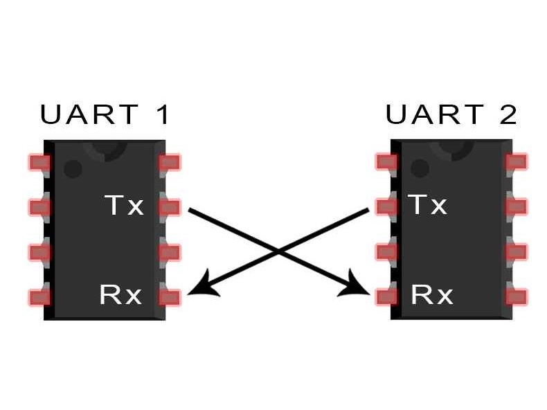
UARTs transmit data asynchronously, which means there is no clock signal to synchronize
the output of bits from the transmitting UART to the sampling of bits by the receiving
UART. Instead of a clock signal, the transmitting UART adds start and stop bits to the
data packet being transferred. These bits define the beginning and end of the data
packet so the receiving UART knows when to start reading the bits. You can know more
about it from this great Circuit Basics
tutorial.
I connected 3 Xaio RP2040 using UART protocol. One master & two slaves where the the RX
of the slaves is connected to the TX of the master and the TX of the slaves is connected
to RX of the master.
UART Code
Master
#define btn 27
#define btn1 26
void setup() {
  pinMode(btn, INPUT_PULLUP);
  pinMode(btn1, INPUT_PULLUP);

  Serial1.begin(115200);
}

void loop() {
  if (digitalRead(btn) == LOW) {
    Serial1.write('1');
  }

  if (digitalRead(btn1) == LOW) {
    Serial1.write('2');
  }
}
Slave
#define led 26
char incomingdata;

void setup() {
  pinMode(led, OUTPUT);
  Serial1.begin(115200);
}

void loop() {
  if (Serial1.available()) {
    incomingdata = Serial1.read();
    // I replaced '1' with '2' for the second slave.
    if (incomingdata == '1') {
      digitalWriteFast(led, HIGH);
      // I replaced '2' with '1' for the second slave.
    } else if (incomingdata == '2') {
      digitalWriteFast(led, LOW);
    }
  }
  delay(10);
}
Challanges
The UART communication didn't work for me at first whenever I send data over usingSerial.write('1') it shows in the serial monitor but nothing comes out of the
pins after some troubleshooting and some research I found out that the RP2040 had 2 serial
ports one which is used while communicating via USB and the other is used via pins.
I found this example that helped me understand how to use the the 2 serial ports.
I just change
Serial to Serial1 in my code and everything worked.