Machine Design
Assignment
- Group Assignment:
- Work and communicate effectively in a team and independently.
- Design, plan and build a system.
- Analyse and solve technical problems.
- Recognise opportunities for improvements in the design.
Output Preview
Machine Build
Idea & Tasks
For this week we worked as a group to design and operate a machine.
- We have gone through several ideas then decided to make Kinetic Sand Table.
- A metal ball- rolling silently through sand to automatically create and erase patterns
- We listed down each machine part and each of us took a specific task, mine was:
Linear Axis
- Design
- Fabrication & Assembly
- Electronics & Programming
- Testing & Documentation
Design & Fabrication
- I start by importing the different components from GrabCAD that I would use while desinging the Linear Axis
- Then I designed the parts I need to assemble my mechanism
- Then I assembled all the part together.
- Then I fabricate a assembled my parts
Electronics & Programming
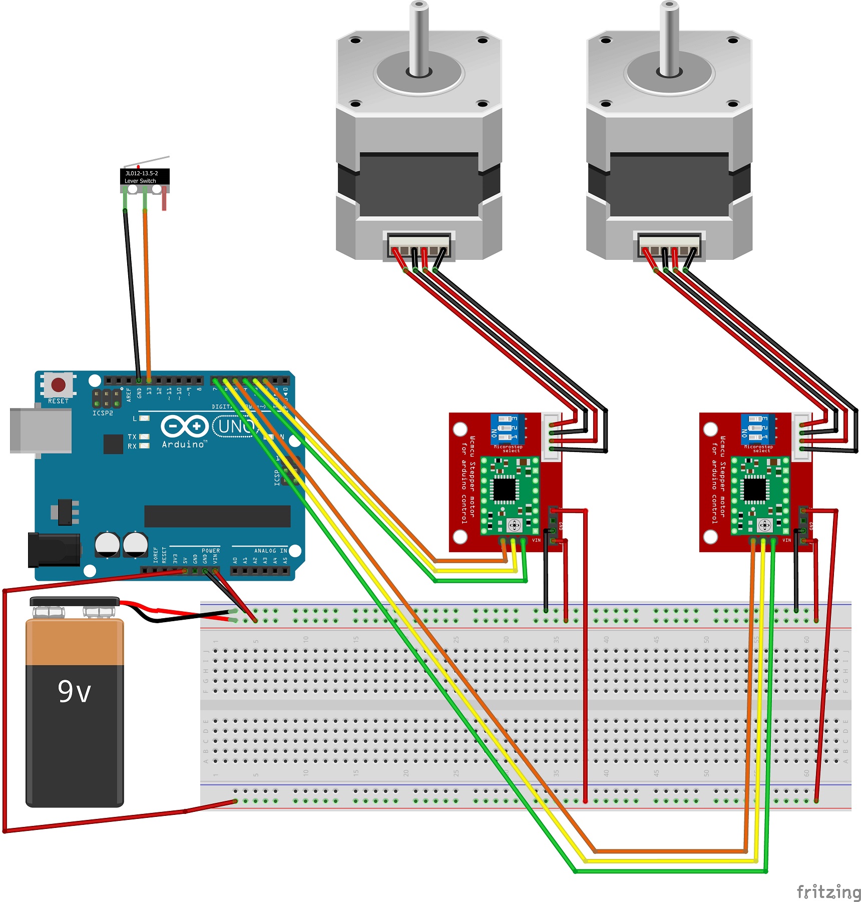
The electronics we used for our machine are:
- Arduino UNO
- A4988 Modules
- Stepper Motors
- 9V Power Adaptor.
Wiring Diagram
Arduino Code
// Define connections for Motors
#define stepA_stepPin 2
#define stepA_dirPin 3
#define stepA_enablePin 4
#define stepA_homeSwitchPin 13

#define stepB_stepPin 5
#define stepB_dirPin 6
#define stepB_enablePin 7

#define steps_per_arm 3250          //3250 for full arm len
#define steps_per_revolution 9600   //200 * 3 ratio * 16 microstepping = 360 deg

// Define motion speed and direction parameters
bool stepA_dir_out = true;
bool stepA_dir_in = false;
bool stepB_dir_left = true;
bool stepB_dir_right = false;
int step_delay = 500;


void setup() {
  // Set up stepper motor pins as outputs
  pinMode(stepA_dirPin, OUTPUT);
  pinMode(stepA_stepPin, OUTPUT);
  pinMode(stepA_enablePin, OUTPUT);
  pinMode(stepB_dirPin, OUTPUT);
  pinMode(stepB_stepPin, OUTPUT);
  pinMode(stepB_enablePin, OUTPUT);

  // Setup limit switch as input
  pinMode(stepA_homeSwitchPin, INPUT_PULLUP);

  // Enable both steppers
  digitalWrite(stepA_enablePin, LOW);
  digitalWrite(stepB_enablePin, LOW);

  // Perform homing sequence for Stepper A
  while (digitalRead(stepA_homeSwitchPin) == HIGH) {
    stepA_run(1, stepA_dir_out);
  }

  // Go to table center
  stepA_run(steps_per_arm, stepA_dir_in);
}

void stepA_run(int steps, bool dir) {
  stepper_run(steps, dir, stepA_stepPin, stepA_dirPin);
}

void stepB_run(int steps, bool dir) {
  stepper_run(steps, dir, stepB_stepPin, stepB_dirPin);
}

void stepper_run(int steps, bool dir, int stepPin, int dirPin) {
  for (int i = 0; i < steps; i++) {
    digitalWrite(dirPin, dir);
    digitalWrite(stepPin, HIGH);
    delayMicroseconds(step_delay);
    digitalWrite(stepPin, LOW);
    delayMicroseconds(step_delay);
  }
}

void loop() {
    stepB_run(steps_per_revolution/4, stepB_dir_left);
    stepA_run(steps_per_arm*0.8, stepA_dir_in);
    stepB_run(steps_per_revolution/4, stepB_dir_right);
    stepA_run(steps_per_arm*0.8, stepA_dir_out);
}
Testing
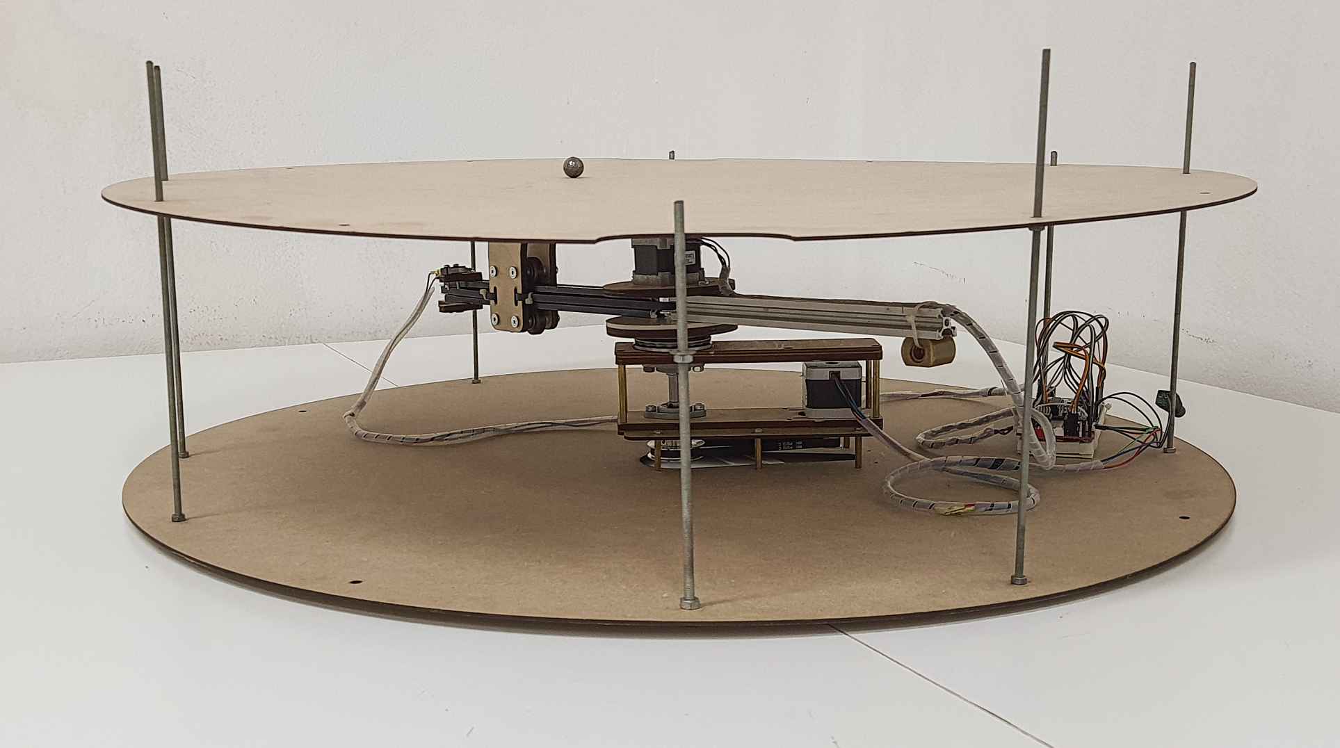
Hero Shot
Future Improvements
- Make the electric slip ring mechanism
- Homing the rotary axis
- Add a G-code processor
- Adding lights and other features
Challange
- Unfortunately, The Linear Axis was front heavy we had to add a counter weight at the back to balance the axis.
- At first the machine was very noisy and moved in a very jittery manner. To achieve smooth movement, we experimented with different microstepping settings, optimizing for the best possible performance. Microstepping is a technique used to improve the resolution and accuracy of stepper motors. For example, if a stepper motor has a full step of 1.8 degrees, microstepping could divide each full step into 16 micro-steps of 0.1125 degrees. This would provide a smoother and slower movement of the motor..