Electronics Production
Assignment
- Group Assignment:
- Characterize the design rules for your in-house PCB production process: document feeds, speeds, plunge rate, depth of cut (traces and outline) and tooling.
- Document your work to the group work page and reflect on your individual page what you learned.
- Individual Assignment:
- Make and test the development board that you designed to interact and communicate with an embedded microcontroller.
Evaluation Standards
- Linked to the group assignment page.
- Documented how you made (mill, stuff, solder) the board.
- Documented that your board is functional.
- Explained any problems and how you fixed them.
- Uploaded your source code.
- Included a 'hero shot' of your board.
Output Preview
Group Assignment
Characterization
We start by characterizing the design rules for our Roland
MDX 20.
we used 0.4mm V-bit for the traces and 1.2 Endmill for the outline.
We set the cutting speed for the to be 4mm/s, and we set the cutting speed for the
outline is 2mm/s
Our Lovely Modela with a fresh surfaced bed.

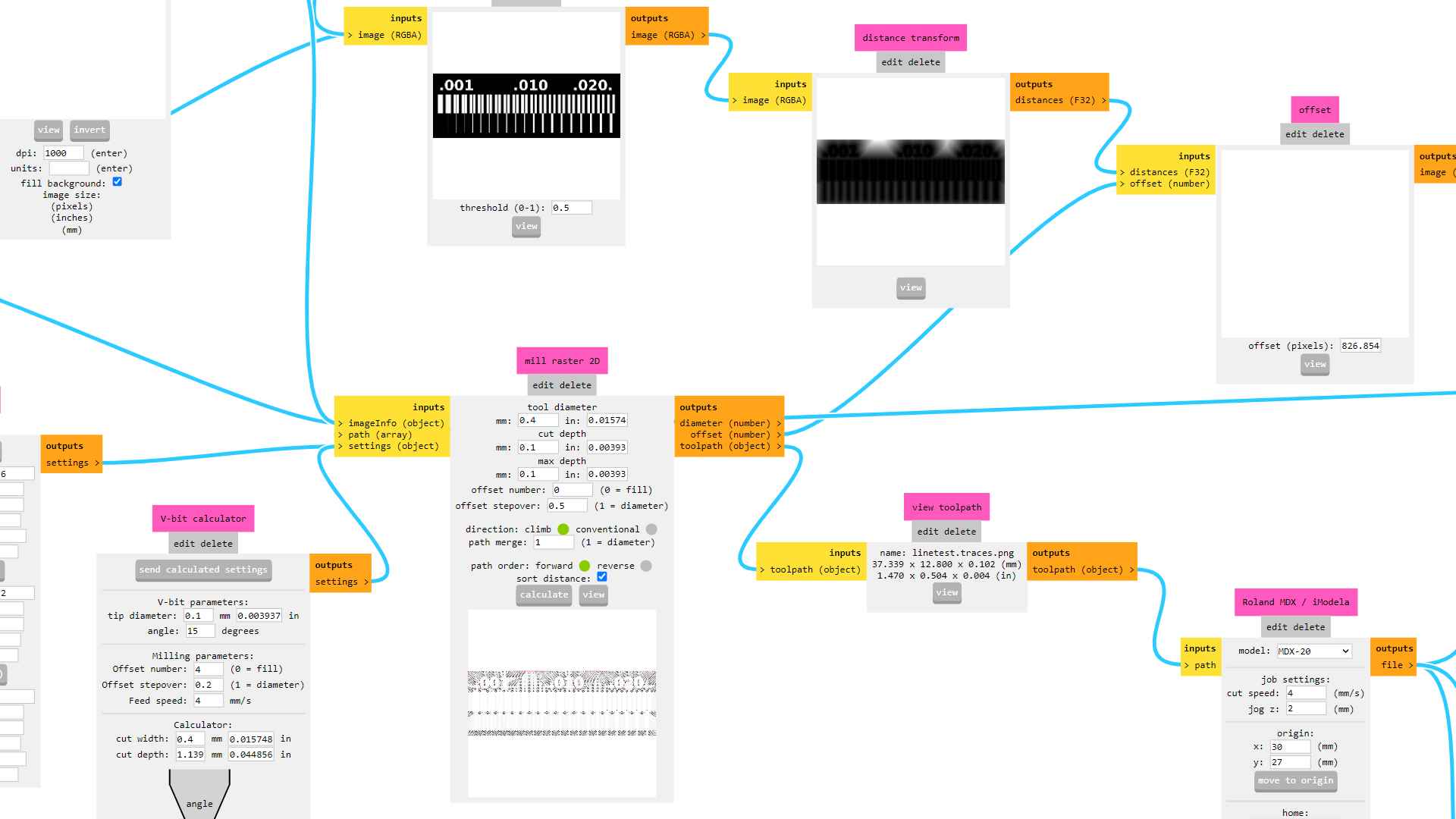
Calculating the toolpath for the design using Mods.
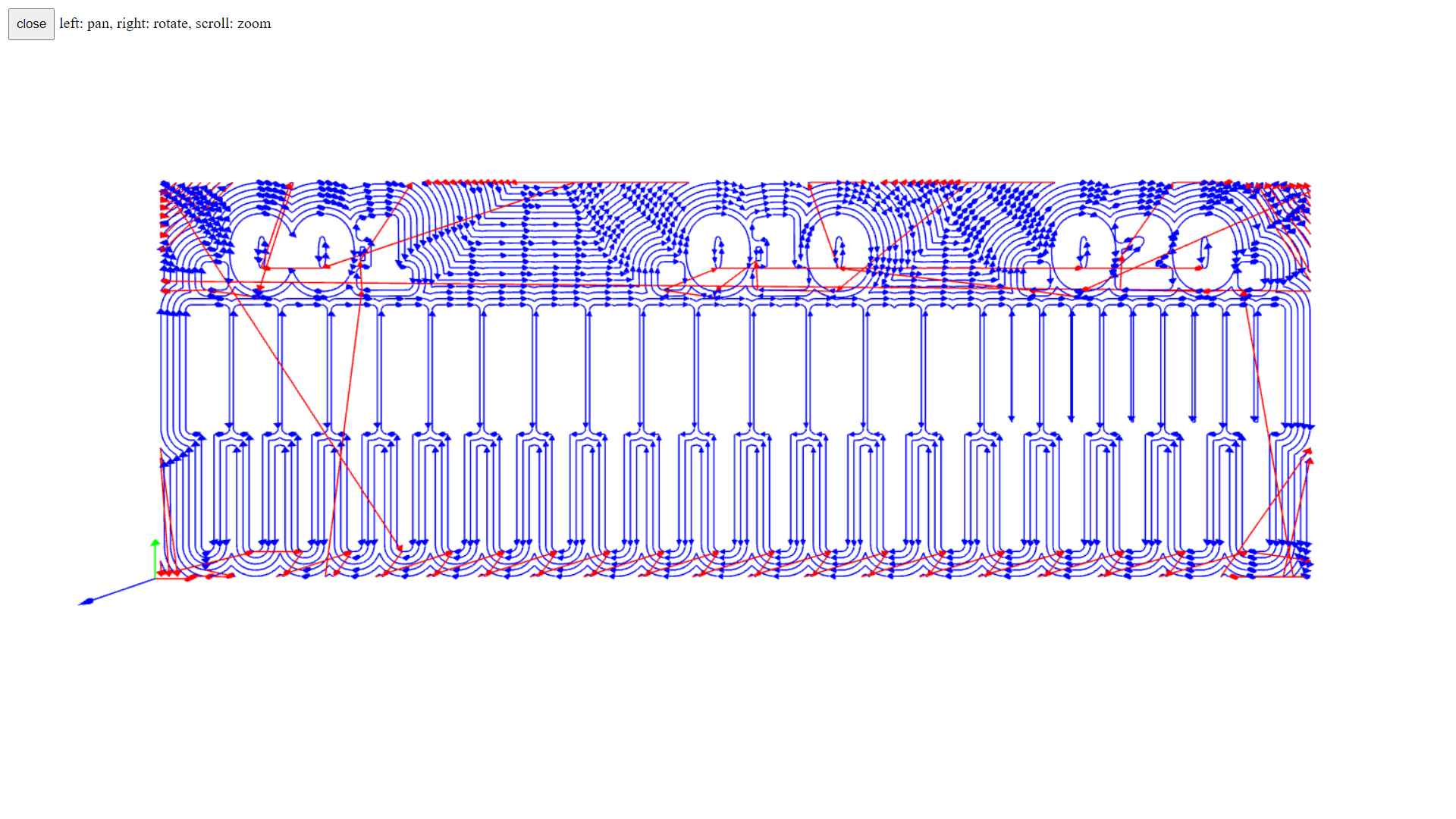
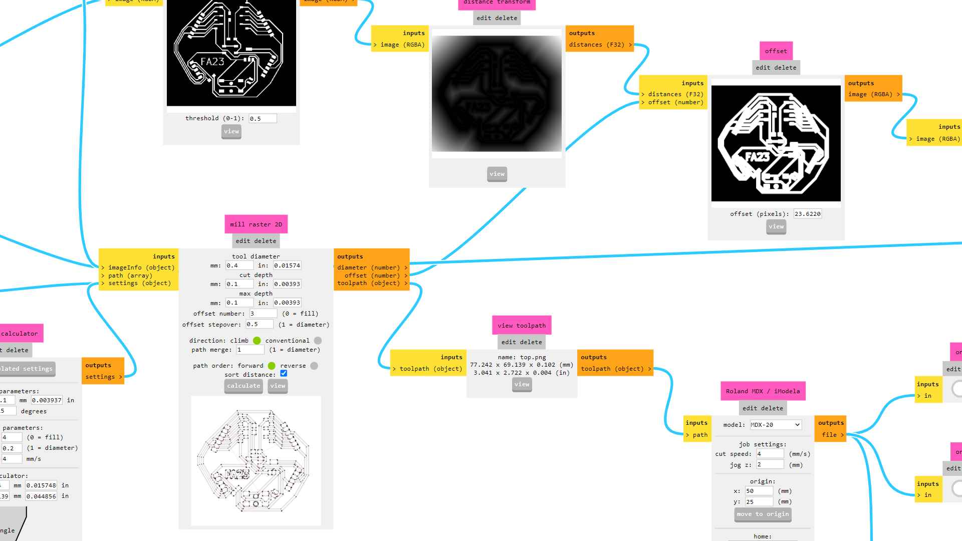
 Viewing the toolpath.
 Using 1.2mm Endmill for outline and 0.4mm V-bit for traces.
 Setting the origin and start the process.
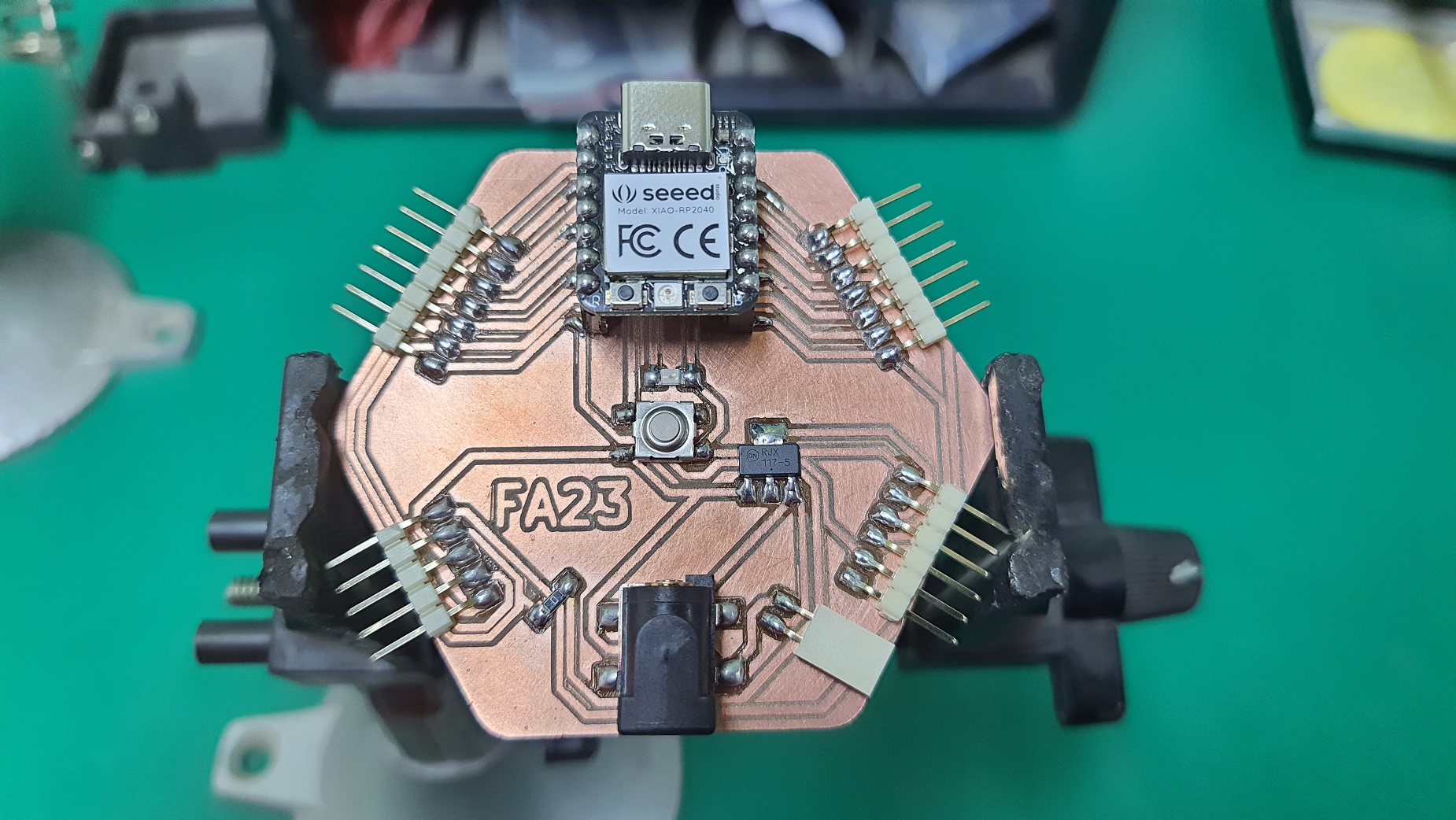
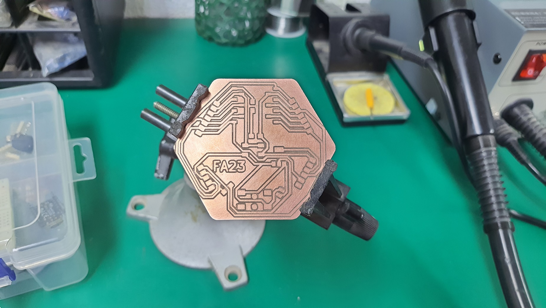
 Here is our hero shot!.

Check our
Group assignment page to see more of our assignment.
PCB Production
- I fabricated my pcb design using FR1 PCB milled on Roland MDX 20
- I Used duoble face to secure the PCB to the bed of the machine
- Then I imported my PNGs into mods and set the tool diameter that I use (V-Bit 0.4mm).
- Then Then I calculated my toolpath using Mods

Then I start stuffing the PCB with the components into my PCB.
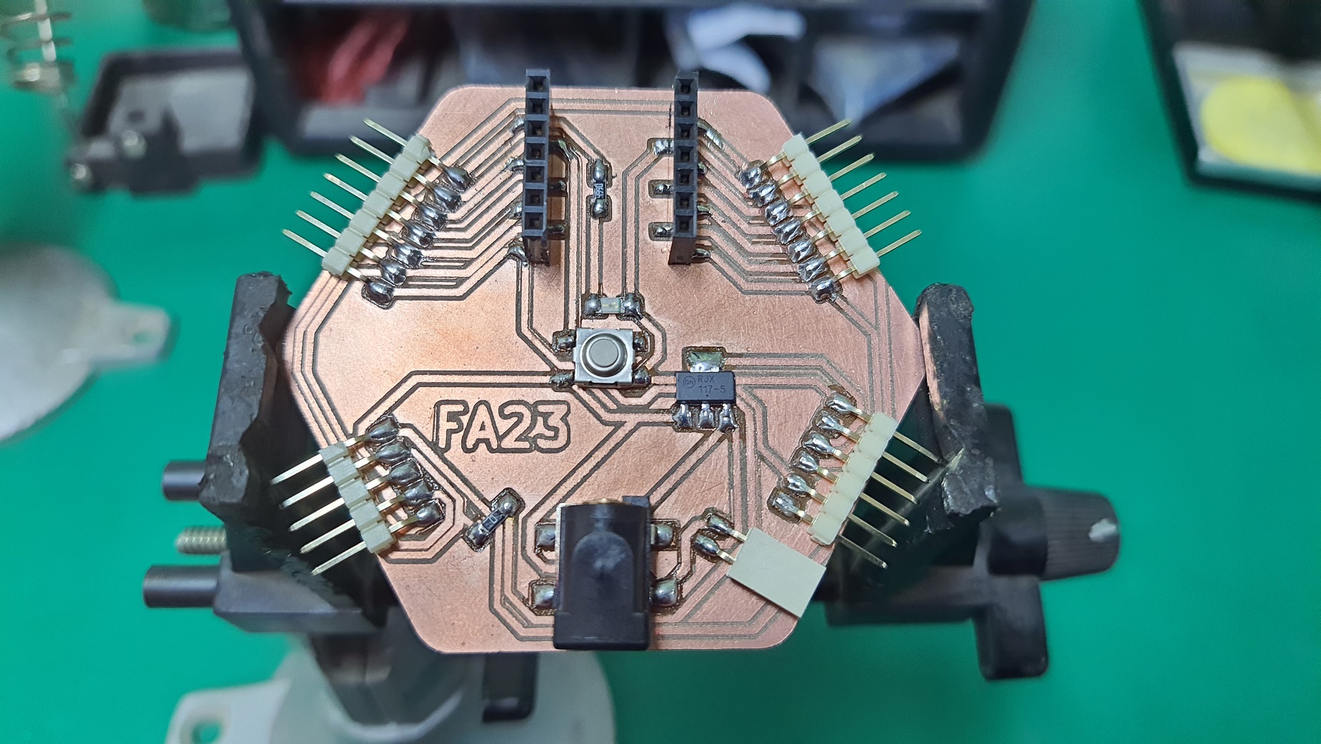
Then I testing PCB by write a simple code to check if it works.
Arduino C
#define led 26
#define btn 27

void setup() {
  pinMode(btn, INPUT_PULLUP);
  pinMode(led, OUTPUT);
}

void loop() {
  if (digitalRead(btn) == LOW) {
    for (int i = 0; i < 3; i++) {
      digitalWrite(led, HIGH);
      delay(1000);
      digitalWrite(led, LOW);
      delay(1000);
    }
  } else {
    digitalWrite(led, LOW);
  }
}