Embedded Programming 1: Blinking an LED
5 Ways to blink an LED with an RP2040
Blinking With Block-Based Visual Programming
One of the most straight forward ways of programming your microcontroller is using blocks. MicroBlocks is an accessible tool that allows you to do just that. It can even run in a browser (chrome or edge), requiring no installation.
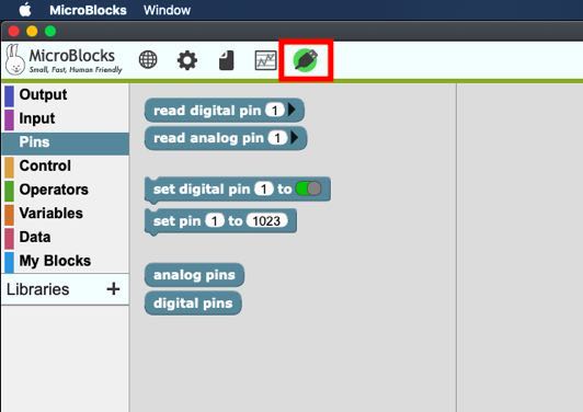
Once you are in MicroBlocks, the first step is to connect your microcontroller. If it succeeds, the button should turn green:
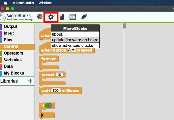
If this step doesn’t succeed, you probably need to update the firmware on the board:
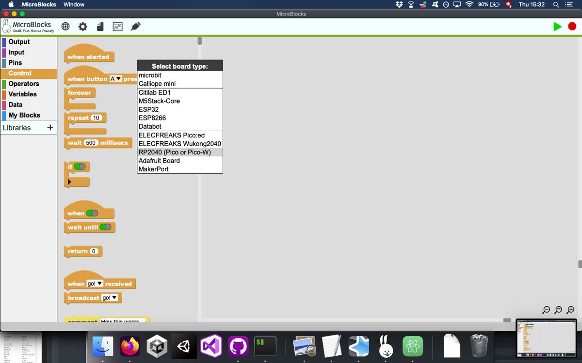
Select the RP2040:
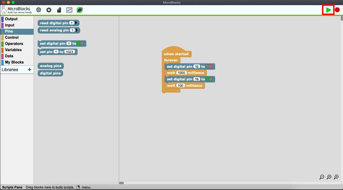
Once you are connected to the RP2040, you can start programming with blocks. When you want to test your code, press the play button (here is the code for blinking the green LED):
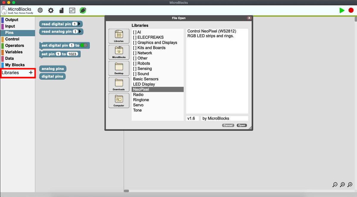
It is also possible to play with the RGB LED. For this, you’ll need to add the NeoPixel library:
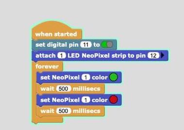
Here is a short example showing how to change the LED color. Pay attention to the pin 11 that needs to be set HIGH. The RGB LED is then attached to pin number 12.
Blinking with MicroPython
Set up for coding in MicroPython
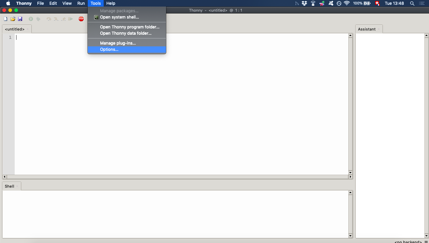
We’ll follow this tutorial that you can check if you want to go further. First, download the Thonny IDE and install this software. Then launch Thonny and go to Tools > Options:
Chose the Interpreter tab and select the MicroPython(Raspberry Pi Pico) interpreter. You can leave the Port to Try to detect port automatically.
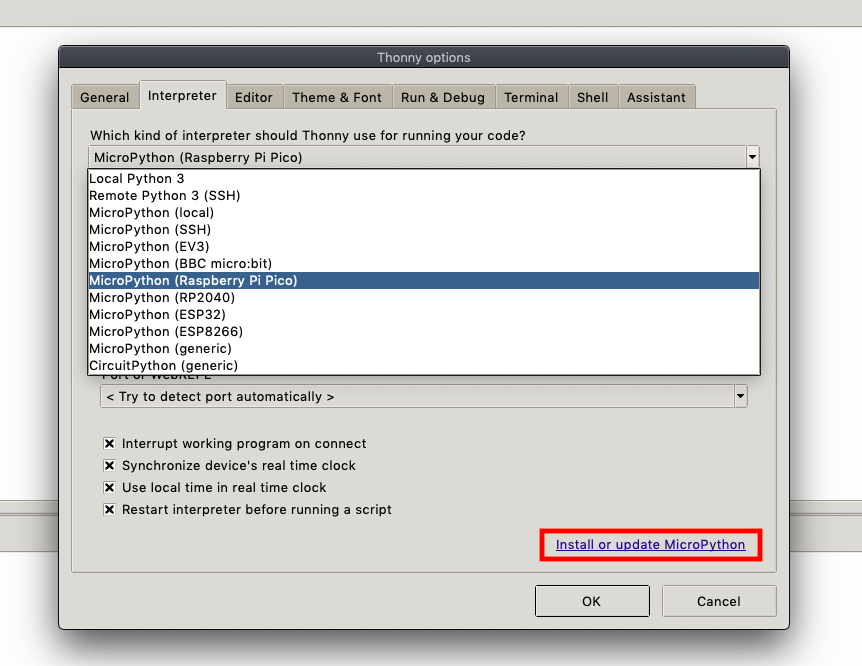
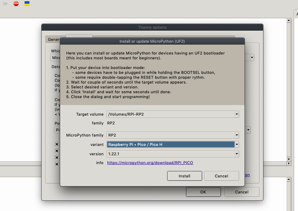
Afterwards, you need to set the board to bootloader mode. On the Seed Studio RP2040, you can achieve this by pushing the RESET (R) and BOOT (B) buttons simultaneously. Go now to Install or update MicroPython.
The Target volume should be automatically set to your RP2040. Select the MicroPython variant: Raspberry Pi . Pico / Pico H:
If no volume is selected once you have set the board to bootloader mode, try to push the buttons again, several times if it is still not working. If nothing happens, try the following:
-
Change the interpreter to MicroPython (RP2040)
-
Select manually the port corresponding to your RP2040 under Port or WebREPL.
-
Go back to Install or update MicroPython and set the board to bootloader mode until you see something in Target volume.
-
Once the Installation is done, switch back the Port to Try to detect port automatically
Coding the blink with MicroPython
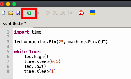
The code for blinking the LED is the following:
import time

led = machine.Pin(25, machine.Pin.OUT)  #sets the pin 25 to OUTPUT mode

while True:
    led.high()                          #sets the pin 25 to HIGH
    time.sleep(0.5)                     #waits 500 ms
    led.low()                           #sets the pin 25 to LOW
    time.sleep(1)
Once you have coded your program, press Run current script. An LED on your board should start blinking.
NOTE
On the RP2040, setting the pin HIGH turns OFF the LED and setting the pin LOW turns ON the LED. This is the opposite behavior of many other microcontrollers, like the Arduino.
Blinking with c++
Set up for coding in c++
The first step is to download the Arduino IDE and to install it.
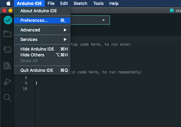
Since the RP2040 is not supported by the Arduino IDE by default, we need to add it to the boards. In order to do this, go to Preferences:
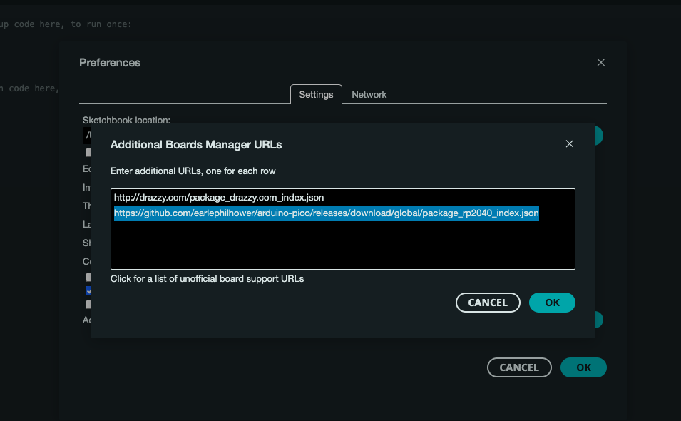
Then, press this button:
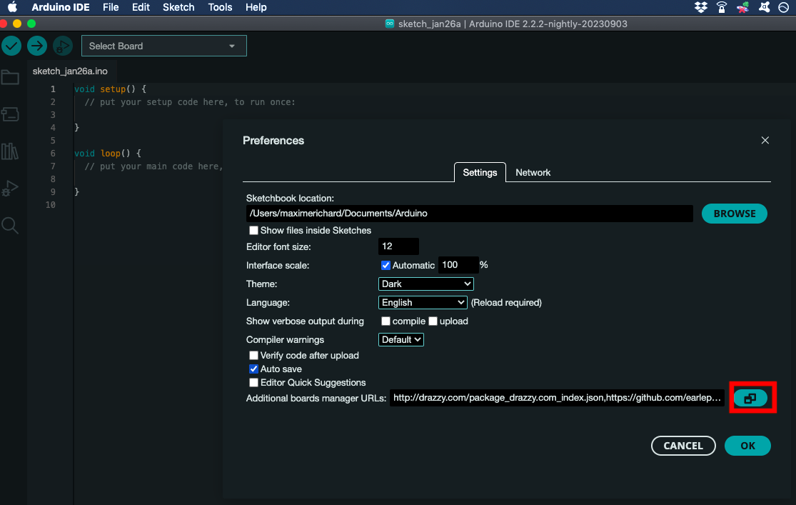
Paste the link that you’ll find here to the Additional boards manager URLs. Currently, this link is the following, but it might change over time:
https://github.com/earlephilhower/arduino-pico/releases/download/global/package_rp2040_index.json
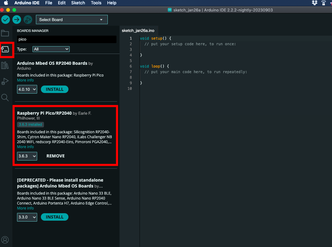
Afterwards, you need to install the board. Go to the Boards Manager accessible from the left panel. Search for pico and install Raspberry Pi Pico/RP2040 by Earle Philhower:
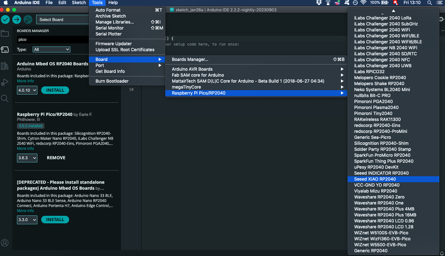
The boards should be installed and you can now navigate to Tools > Board > Raspberry Pi Pico/RP2040 > Seed XIAO RP2040:
After connecting your RP2040 to your computer, it should show in Tools > Port. In Windows, it often shows as COMX, where X is a number.
Coding the blink with c++
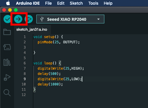
Here is an example of how to blink the LED on pin 25:
void setup() {
  pinMode(25, OUTPUT);    //sets the pin 25 to OUTPUT mode
}

void loop() {
  digitalWrite(25,HIGH);  //sets the pin 25 to HIGH
  delay(500);             //wait for 500ms
  digitalWrite(25,LOW);   //sets the pin 25 to LOW
  delay(500);
}
Once your code is written, push the Upload button:
Playing with Registers
From this instructables, a register is “a chunk of memory usually consisting of anywhere from 8 to 64 bits of data. Each bit is assigned a value of 1 or 0, and the value of each bit in the MANY different registers in a microcontroller tell the rest of the system what to do and when to do it.” It is useful to manipulate registers directly when you want to get faster bit manipulation or when you want to reduce the size of your program.
In the code below, the volatile keyword is used to tell the compiler that the value of the variable can change anytime. It prevents the compiler to optimize it(remove it), even if it looks that the code itself doesn’t modify it.
void setup() {
  /*
  The User Bank IO registers start at a base address of 0x40014000 (defined as IO_BANK0_BASE in SDK). The offset 0x0cc is for GPIO25_CTRL.
  0x400140cc: GPIO25_CTRL: GPIO 25 control including function select and overrides.
  0x05: from "2.19.2. Function Select": selects function SIO (Single-Cycle IO).
      SIO enables the CPU to directly interact with GPIO pins without going through the external peripherals.
  */

  // same for GPIO26_CTRL
  *((volatile unsigned int*) 0x400140cc) = 0x05;

  /*
  Output enable registers, GPIO_OE and GPIO_HI_OE, are used to enable the output driver. 0 for high-impedance (for input mode), 1
  for drive high/low based on GPIO_OUT and GPIO_HI_OUT.
  sets the 25th bit of this register to 1 in order to enable output
  */
  *((volatile unsigned int*) 0xd0000020) = (1 << 25);  // GPIO_OE
}

void loop() {
  /*
  toggles the pin 25 high and low
  1 << 25 shifts 1 left by 25 bits
  ^= → XOR Operation (Toggle)
  */
  *((volatile unsigned int*) 0xd000001c) ^= ( 1 << 25);
  delay(200);
}
Let’s get rid of any Arduino-specific code and rewrite the same program as:
int main() {
        *((volatile unsigned int*) 0x400140cc) = 0x05;
        *((volatile unsigned int*) 0xd0000020) = (1 << 25);

        while( 1 )
        {
          *((volatile unsigned int*) 0xd000001c) ^= ( 1 << 25);
          unsigned int cycles = 125000000;
          while (cycles--) {
            __asm__ volatile ("nop"); // No-operation instruction to waste time
          }
        }

        return 0;
}
Challenge
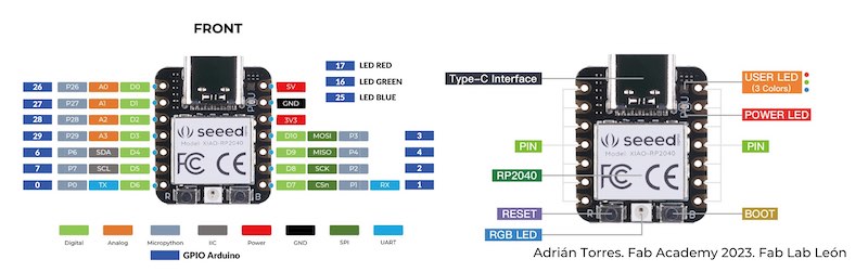
We blinked the blue LED on the XIAO RP2040 using different methods. As a challenge, try to do the same for the green LED. Use the RP2040 datasheet and the XIAO pinout:
What to do if your RP2040 doesn’t work
If the RP2040 is not recognized by Arduino IDE or if you cannot upload any code on it after multiple attempts, you can try the following:
-
Download the blink uf2 file.
-
Press the Reset and Boot buttons of the RP2040 board (R and B buttons) simultaneously.
-
A new hard drive should appear on your computer.
-
Copy the blink uf2 file that you downloaded to this new drive.
-
Once the file has been copied, the RP2040 should be visible to your Arduino IDE and an LED from the RP2040 should blink.