Week 16: Applications and Implications
What will it do? Who’s done what beforehand?
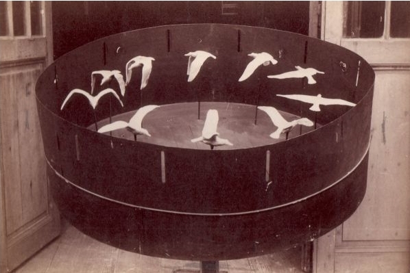
My final project will be a zoetrope. This kind of devices uses the persistence of vision and the phi phenomenon to animate still images placed on a rotating disc. These images can be seen, for example, through narrow slits:

My goal is to make some simple animation of 3D printed solids using the stroboscopic effect created by flashing LEDs.
During my research, I found few former Fabacademy students who made zoetropes: Juliana Henno and Alex Garcia made a 3D zoetrope that animates a deforming cube. Faisal Al Kilani animated a 3D sculpture based on a Fibonacci sequence and adjusted the rotation speed using Hall effect sensors and PID controlling. In 2022, the Waag Fablab made a zoetrope during the machine week.
Mat Collishaw made some large 3D printed animated sculptures that look really beautiful.
Akinoro Goto made an incredible animation of a ballet dancer. This one since to use a slightly different technique that doesn’t use a stroboscopic effect, but continuously animates a 2D shape inside a 3D print using a narrow beam of light.
What will you design? What parts and systems will be made? What processes will be used?
For this project, I will have to design:
| Part | Processes |
|---|---|
| Zoetrope itself | Design with Blender; 3D printed objects; maybe some parts could be CNC milled; if some 2D animation is added, laser cutter for cardboard/paper |
| Support for the zoetrope | Design with FreeCAD; Plywood cut with the CNC |
| PCB board capable of controlling LEDs and a DC motor, as well as reading a sensor (probably a Hall effect sensor) | PCB milling, soldering |
What materials and components will be used? Where will they come from? How much will they cost?
| Material/Component | Origin | Approximate Price [$] |
|---|---|---|
| ELECTRONICS | 37 | |
| SAMD11C | our lab | 2 |
| 5V power supply | our lab | 8 |
| LEDs | our lab | 15 |
| DC motor | our lab | 10 |
| motor driver | our lab | 2 |
| ZOETROPE | 24 | |
| 3D printed objects | our lab | 3 |
| paint | our lab | 3 |
| Plywood | our lab | 12 |
| Cardboard and paper | local shop | 3 |
| 20 x magnets | our lab | 3 |
| Support | 12 | |
| Plywood (same as for zeotrope) | - | |
| 2 x bearings | recycled from old printer | 2 |
| metal axis | recycled from old printer | 10 |
| TOTAL | 73 |
What questions need to be answered?
-
How to accurately measure time with the microcontroller?
-
What microcontroller to use?
-
How much power will the whole system need?
-
What sensor should I use?
How will it be evaluated?
-
The first achievement will be to make all the different parts of the system work: DC motor turning the zeotrope, sensor giving data to the MCU and LEDs flashing.
-
The next one will be to be able to see a smooth motion with the eyes, and then the camera.
-
The last one will be the esthetics of the zeotrope.
Make a schedule
| Task | Time allocation |
|---|---|
| 3D modeling for 3D prints | until 25.05 full time, and then until 05.06 |
| 3D printing | 26.05 - 05.06 |
| board design | 26.05 - 28.05 |
| board production | 29.05 - 01.06 |
| CAD design | 28.05 - 01.06 |
| CNC cutting | 29.05 - 05.06 |
| painting | 28.05 - 06.06 |
| assembling and programming | 01.06 - 09.06 |
| video and slide | 09.06 - 10.06 |