Assessments book for this week:
Slides:
http://academy.cba.mit.edu/classes/computer_machining/index.html
group assignment
- do your lab’s safety training
- test runout, alignment, fixturing, speeds, feeds, materials, and toolpaths for your machine
individual assignment
- make (design+mill+assemble) something big (~meter-scale)
- extra credit: don’t use fasteners or glue - extra credit: include curved surfaces
Files
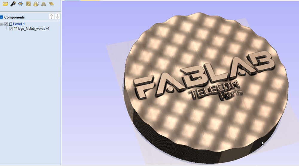
STL file of the Fablab Wave Logo: STL
Fusion 360 file of the chair: f3d file
ShopBot CNC:
Machine introduction
Turn-on the machine using the switch and the key on the right.
In ShopBot, set x and y zero position on the bottom-left corner of the stock or on the center for a round stock, then approach the surface of the stock and set z zero.
This shopbot model need to warm-up the spindle for several minutes before milling. Select Cuts> Spindle warmup routine and set the spindle controler to 150 (9000 turns/minute). The controler go from 0 to 300 corresponding to 0 to 18000 turns/minute.
3D design
To create a 3d sine wave effect on a surface, I follow this tutorial: https://youtu.be/Q_viUk4Ce1s
First we create two coils. The first one using the coil tool of solid section. Only one coil turn of length “wavelength” with diameter “amplitude”. then create a mirror copy of it along “xy plane”. Use triangular shape section.
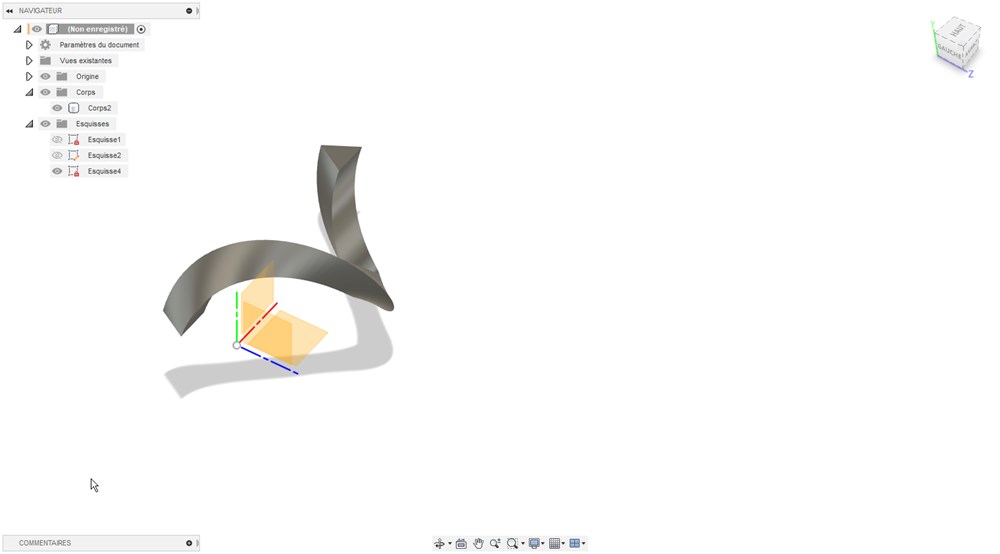 Be sure to use “create new body” option and not “join”.
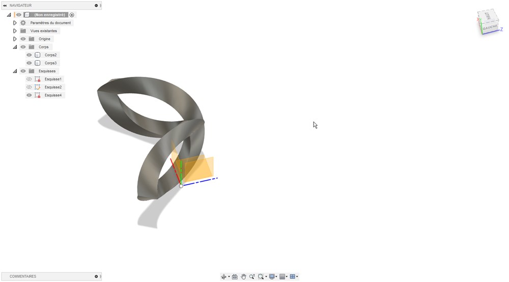 Then create an offset plane at “wavelength/2” distance from yz plane. create a sketch on the first plane, project edge of the first coil on it. Then go to the offset plane to create another sketch and project the second coil.
Under Surface section of fusion, extrude both curve on opposite direction for 10 mm (arbitrary).
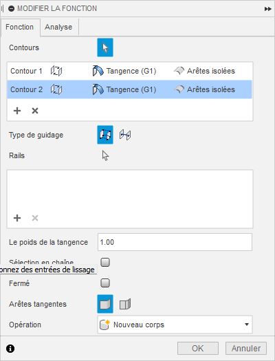
Use the Loft tool to connect the edges of those newly created surfaces.
Under connection type, choose “tangent” to have smooth connection.
Toggle visibility of the two previous surfaces and coils bodies.
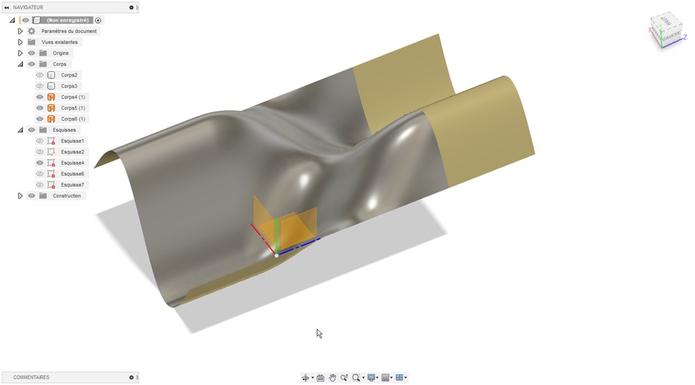
Then select the surface and mirror it
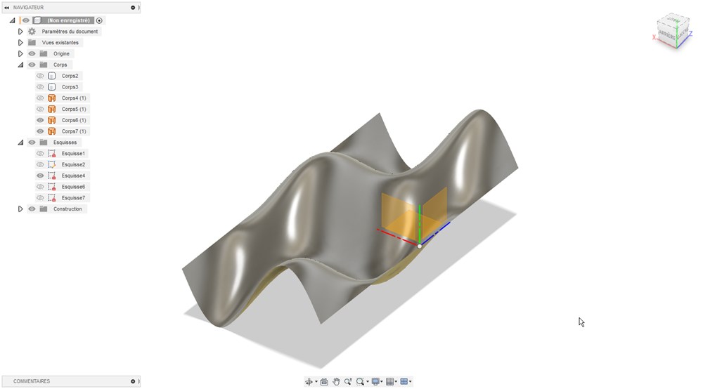
Create a rectangular patern to extend the patern
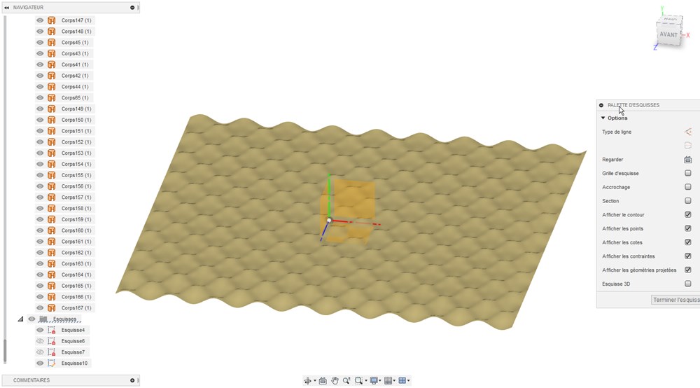
Select all surfaces and select “Sew” (coudre in french version) to merge everything into a unique surface
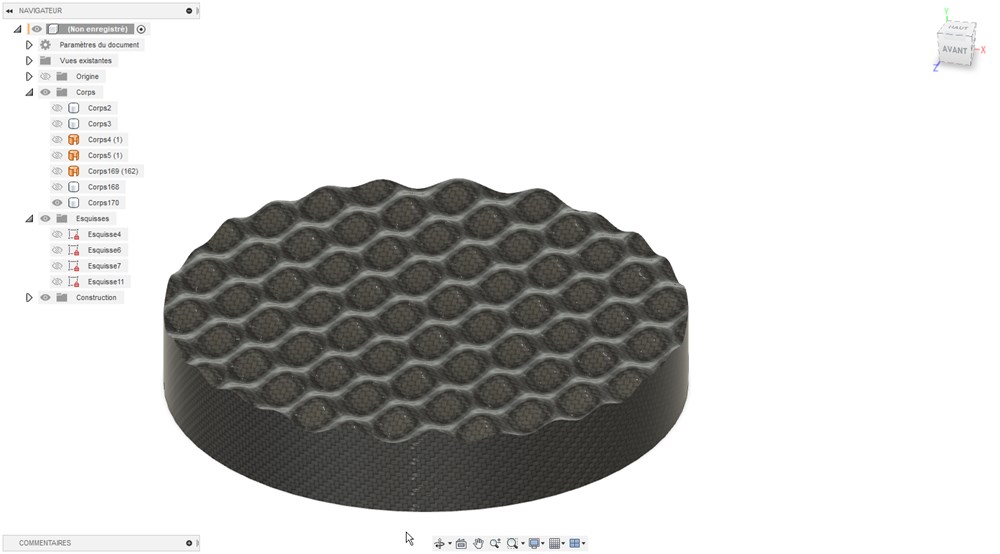
Create a new solid starting from the xy plane, then cut this body using the surface as a tool, finaly delete one of the 2 parts of the splitted body.
We can apply a carbon fiber texture to the component to help visualize pattern thank to the grid aspect of the texture.
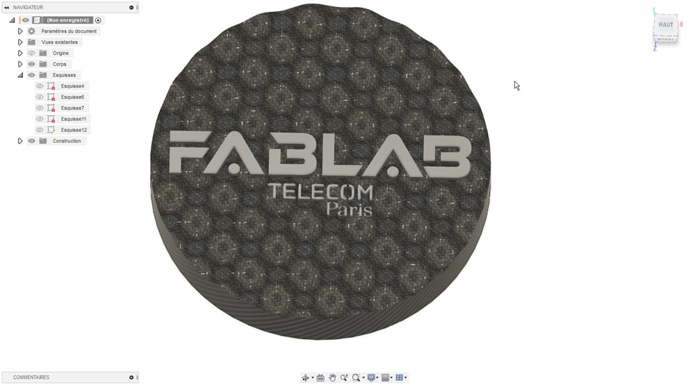
I add an svg of our Fablab logo on the surface, then extrude in both direction.
 We can now export mesh from fusion to stl file and import into VCarve.
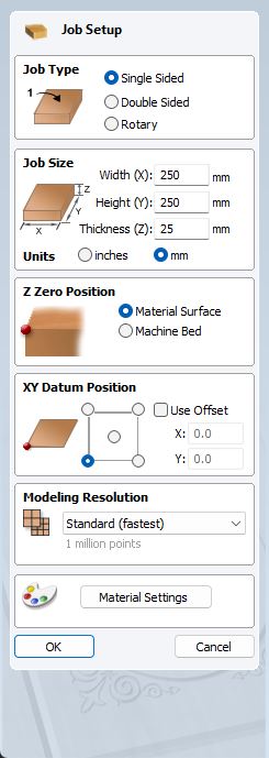
VCarve: import stl file
Stock setting
We adjust those parameters to match our stock characteristics. Set XY Datum Position to center if you use a round stock.
- import stl. File>Import…>Import component/3D model
- Rotate model to fit into the stock into Initial Orientation
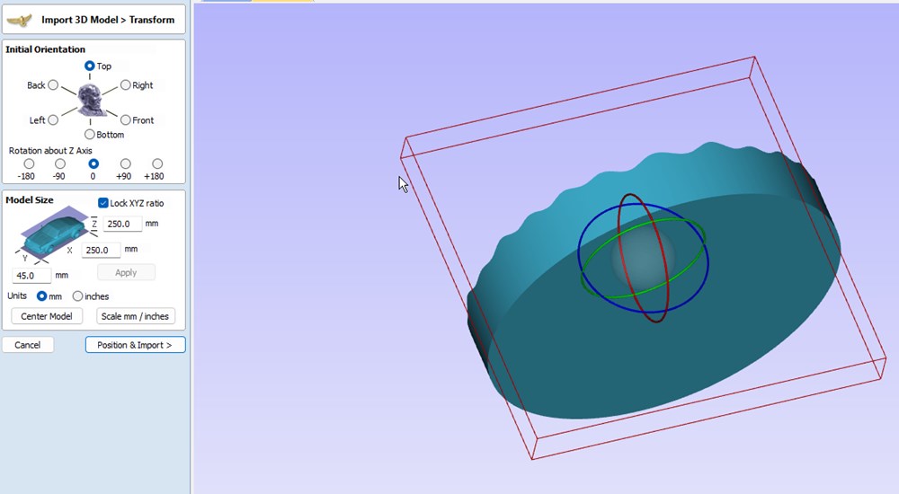
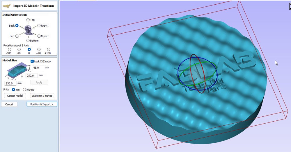
- Click on position & Import button
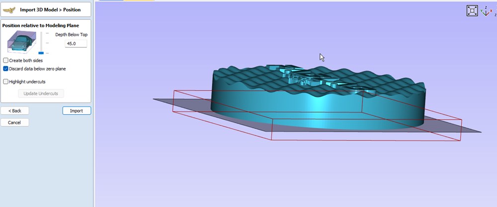
- For Position relative to Modeling Plane, put the limit to the bottom of the model. Everything under this plane will be ignored
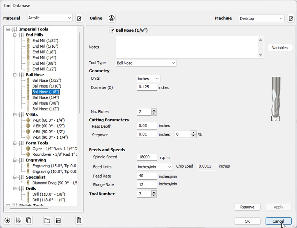
- Click on Toolpath tab and select “Display tool database” to select the bit. In our case, we choose a Ball Nose bit of 1/8" (ref 48014) (TODO verify).
- Choose 3d Finishing toolpath icon. Verify parameters and click OK. On next panel, choose “Model Boundary” under “Machining Limit Boundary”. Finally click on Calculate

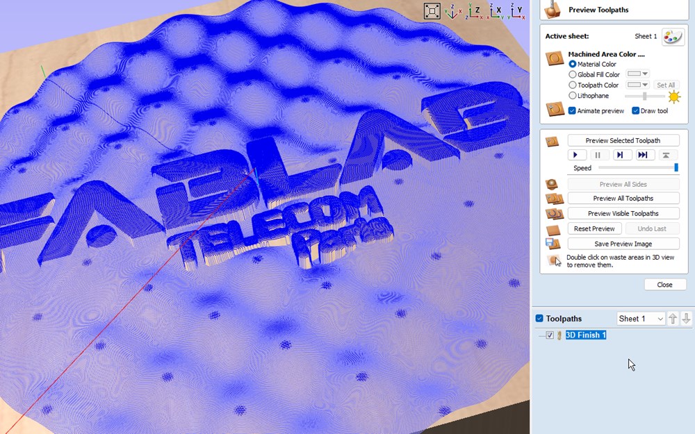
- On the next window, we can verify the toolpath and launch a preview of the tool movements. Not that if you change something in the toolpath, you have to click on “reset Preview” or it will not be updated.
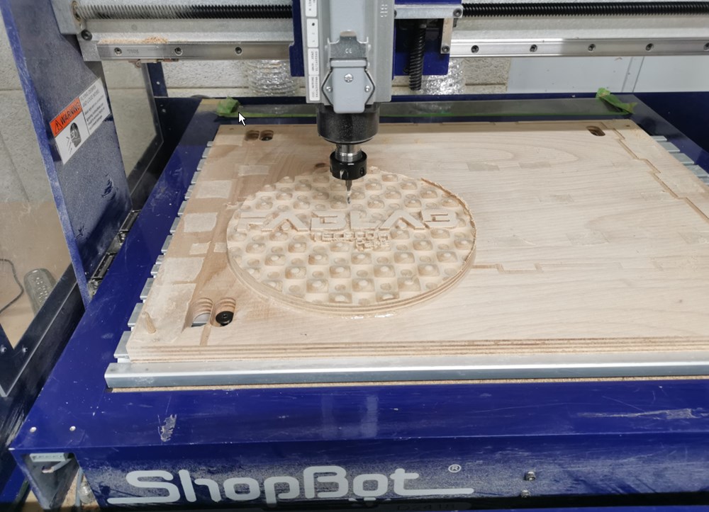
Milling
- Now that the toolpath is created, let’s send it to the machine. Click on Close on the previous windows and click on “Save toolpath” icon. Check “Output direct to machine” checkbox.
- Go to ShopBot controler and run the received job (TODO: add details and snapshot)
Result of the milling:
Video at the begining of the process:
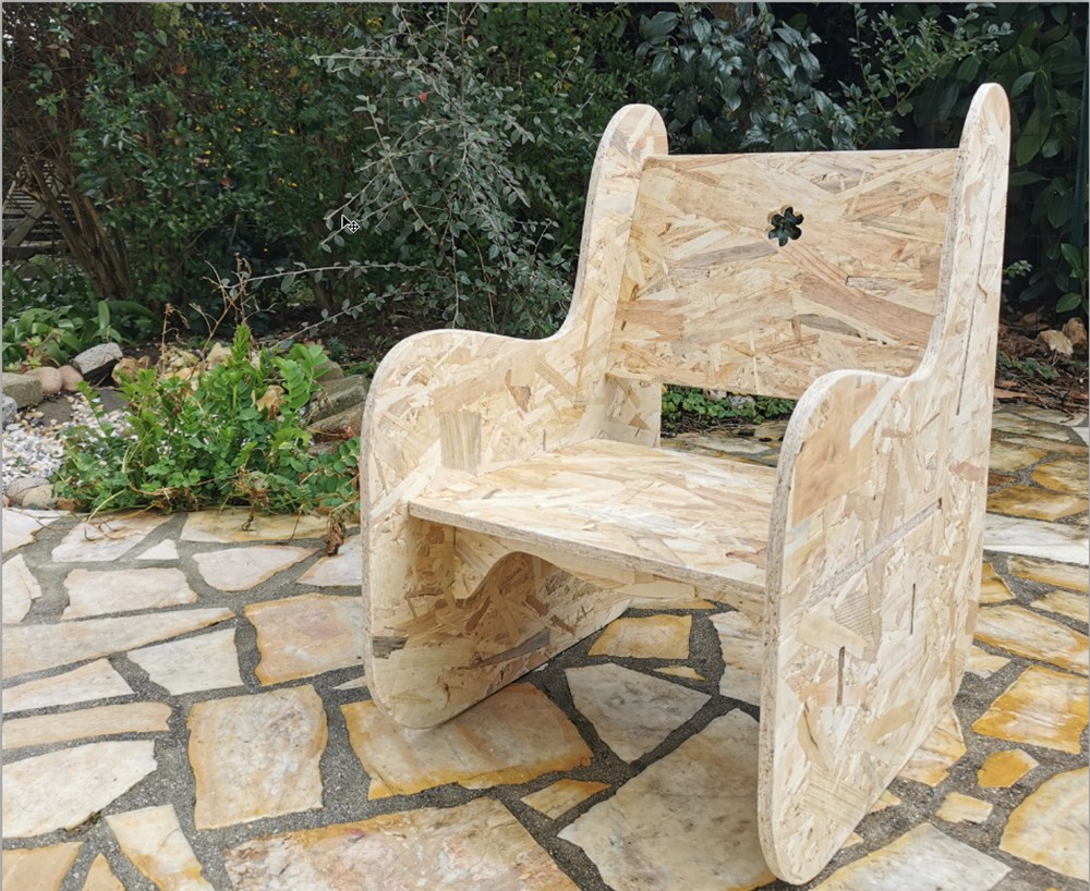
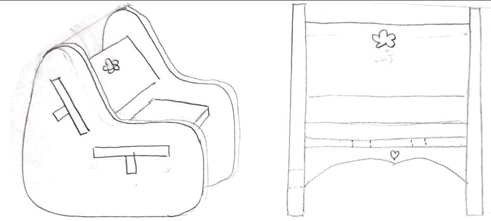
Children Chair
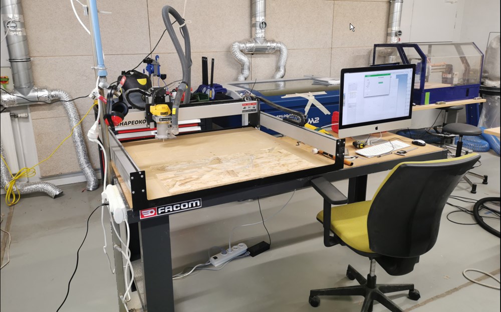
Shapeoko XXL
Our next design is a relatively big size furniture, we will use a CNC with a bigger working area of around 800x800mm.
Hand drawing of the chair, their will be reinforcements on the back and the seat.
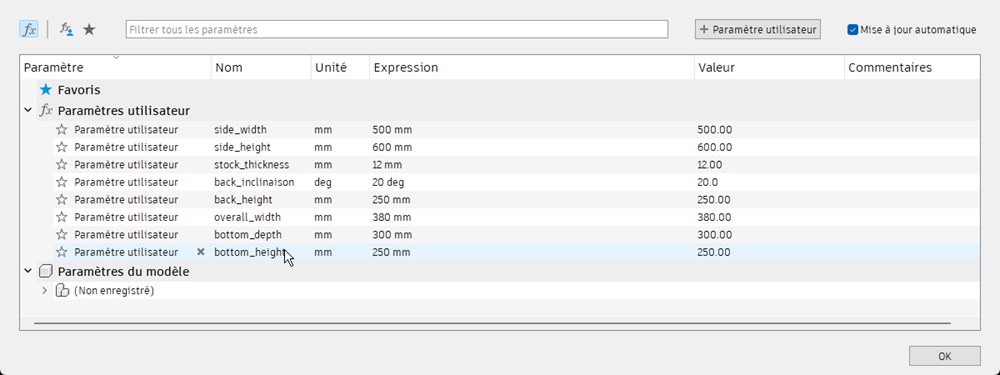
I design this furniture on Fusion360, providing parameters for easy modification, especially for the stock thickness.
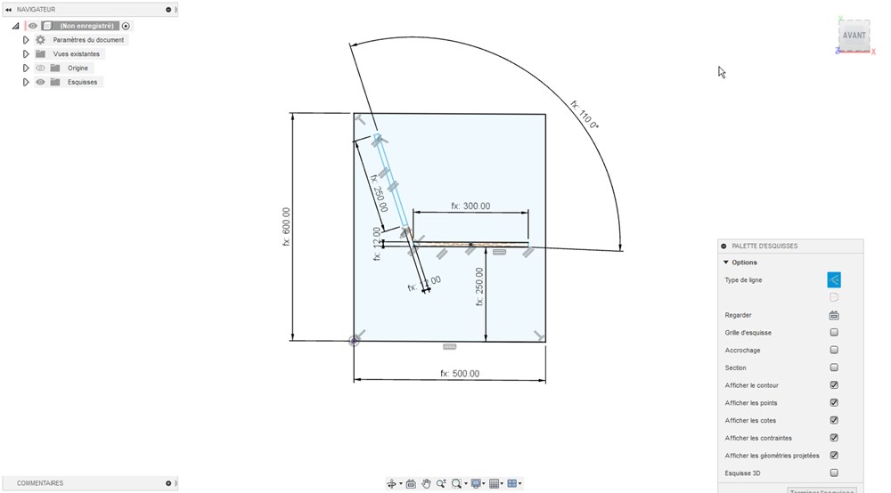
Extruding the side of the chair
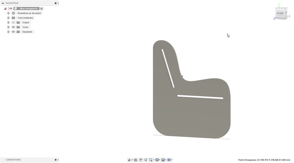
Adding back and bottom plate reinforced with some additional pieces.
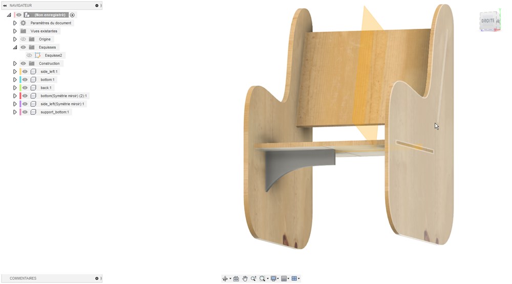
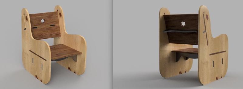
Rendering of the chair with differents wood essences.

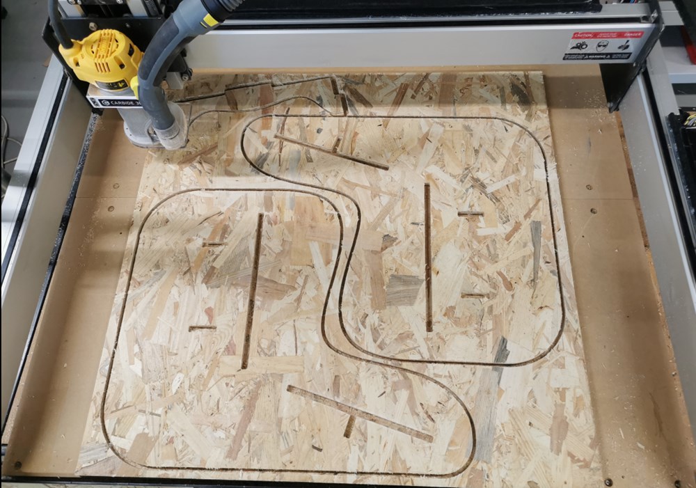
In practice, we use OSB panel for this assigment.
Milling
Final result
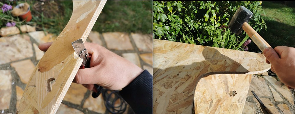
I had to make some adjustement and hamer work to fit everything. I forgot to add dogbone under some angles, it has been solved easily with a cutter. They was another problem with insert dimensions. I do a small scaling adjustement to adjust thickness of the stock setted in Fusion to real thickness of the stock (12mm vs 11.7mm resulting in a scaling factor of 0.975). I probably forgot to scale some of the parts…