Assessments book for this week:
Embedded Programming · GitBook (fabacademy.org)
Slides:
http://academy.cba.mit.edu/classes/embedded_programming/index.html
Group assignment
- compare the performance and development workflows for other architectures
Individual assignments
- browse through the data sheet for your microcontroller - program a microcontroller development board to interact and communicate - extra credit: use different languages &/or development environments
Files
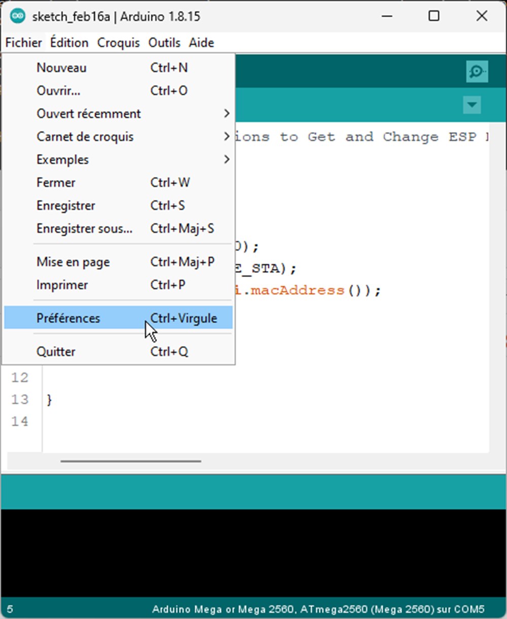
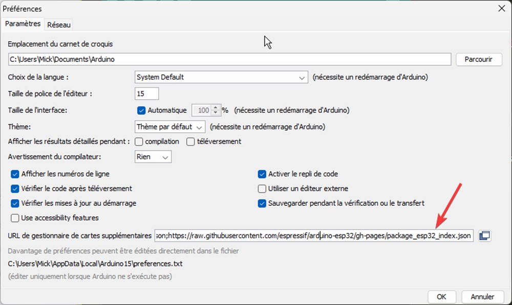
To install a new board wich is not a “classic” arduino, we have to add it to the board library. Go to File>Preferences
add this url to “Additional cards” line, separate from the other with a coma https://raw.githubusercontent.com/espressif/arduino-esp32/gh-pages/package_esp32_dev_index.json
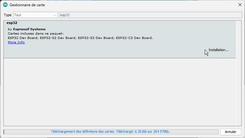
Then in Tools>Card Type>Card manager, search for esp32 and click install
Then select the right board under Tools>card type…>ESP32 Arduino> Xias ESP32C3
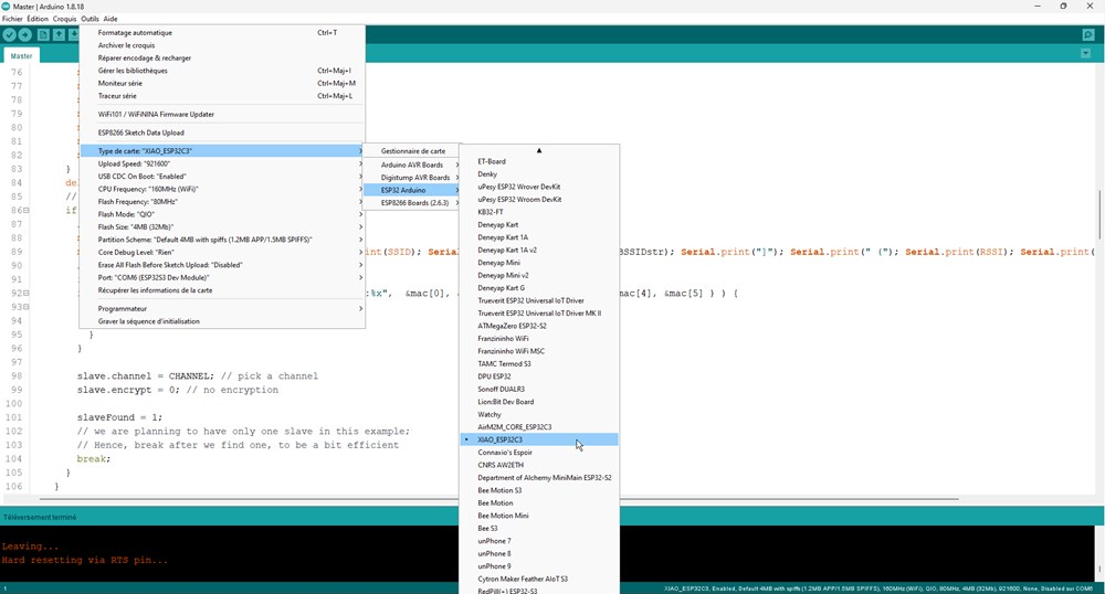
Compilation problem: As soon as I press the compile button, It seems to run forever and the computer start to lag. I finally found that the antivirus was in cause (Avira in my case). Temporarly disabling it fix the problem. I have to find a safer way to compile my sketches!
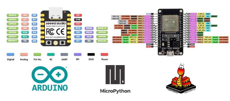
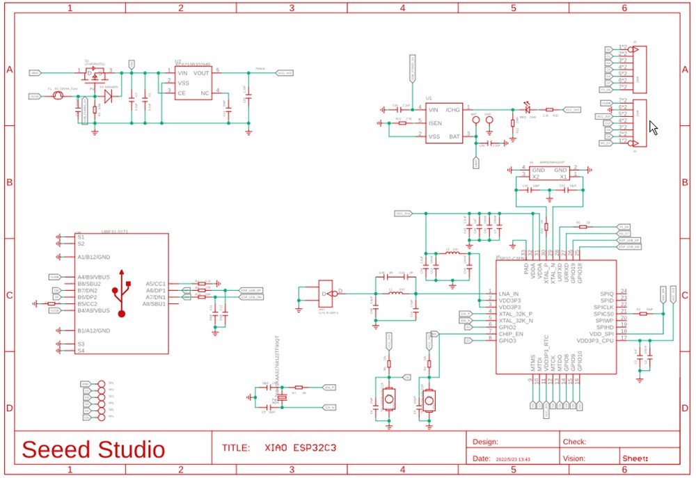
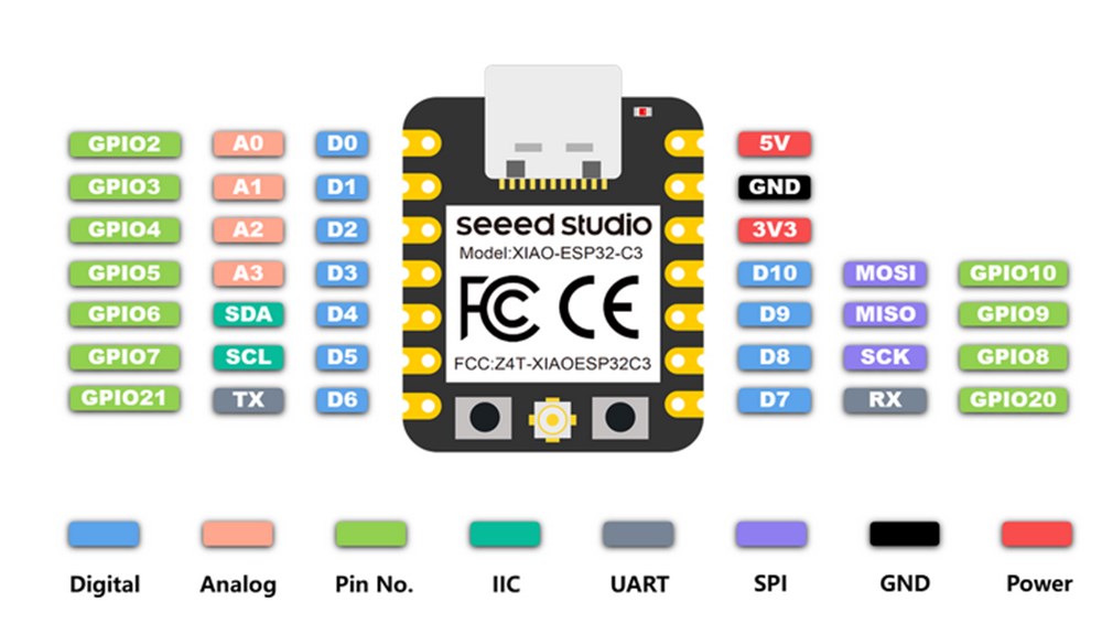
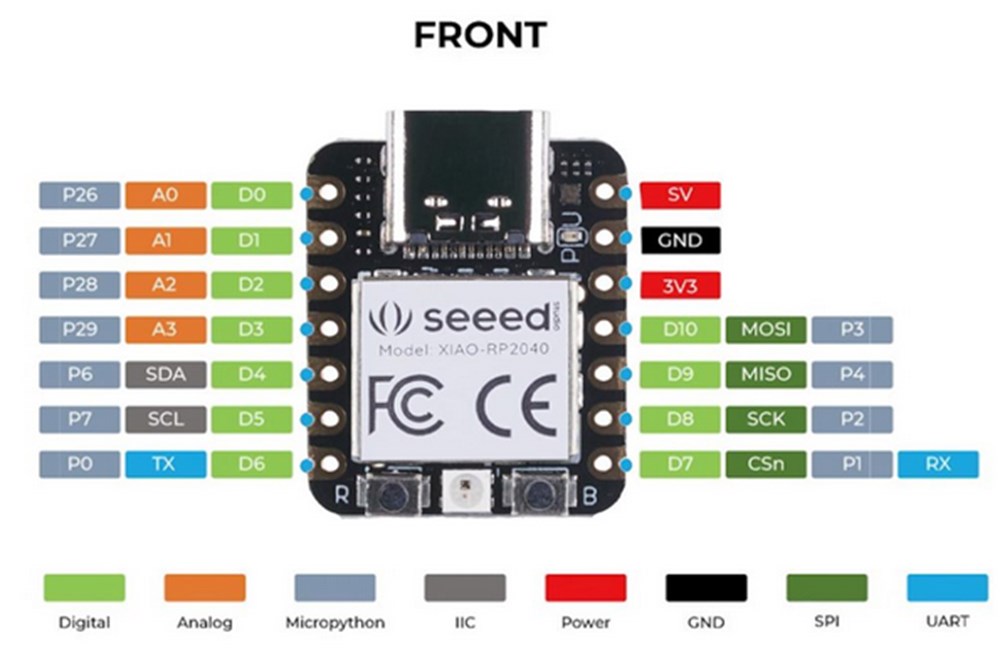
Xiao ESP32C3 characteritics:
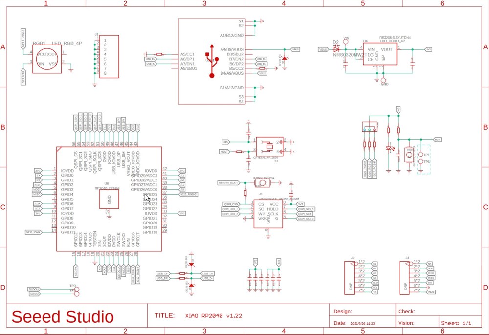
Internal Schematics:
https://files.seeedstudio.com/wiki/XIAO_WiFi/Resources/Seeeduino-XIAO-ESP32C3-SCH.pdf
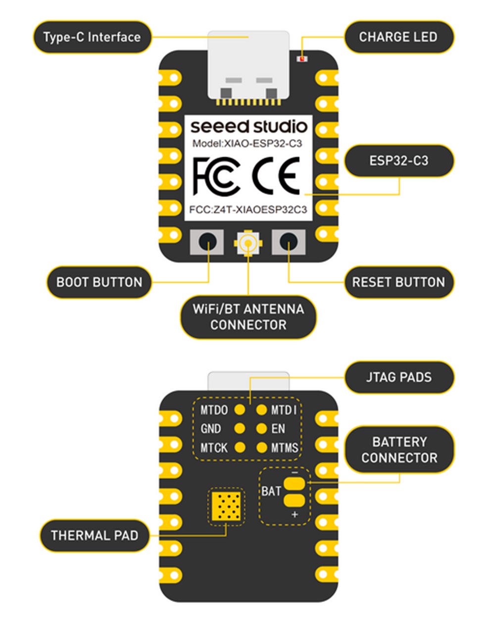
under the metal shield:
 info from https://wiki.seeedstudio.com/XIAO_ESP32C3_Getting_Started/
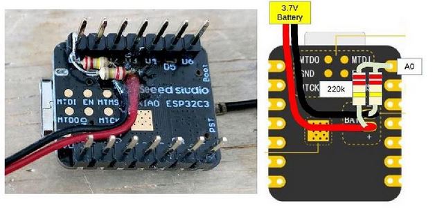
There is even a battery connector, Indeed XIA ESP32C3 can use a 3.7V lithium battery as power input
Testing the beast:
Everything hold in one hand! I wrote a simple sketch displaying a counter on a oled screen (video below). After that, I add a progress bar displaying the charge level of the battery (sketch here)
To monitor the battery, I add 2 200k resistor as explain in this schematic taken from seed-studio website, then read the analog value on A0
|
|
Wireless communication
Testing ESPNOW example to communicate beetween two ESP32.
Now lets create a program by ourself
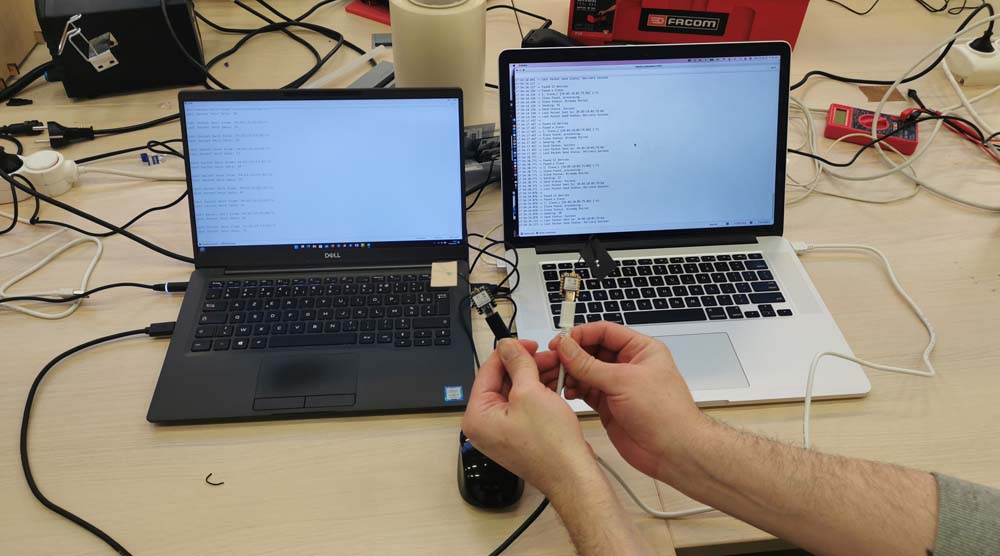
First get the mac adress of the ESP. To do that
|
|
The First MAc adress is 34:85:18:03:42:74 The second is: 34:85:18:03:75:BC
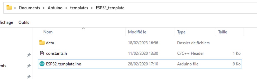
ESP32 as a file server
First, install SPDIFF support for esp32 folowing this tutorial https://randomnerdtutorials.com/install-esp32-filesystem-uploader-arduino-ide/
Install filesystem plugin https://github.com/me-no-dev/arduino-esp32fs-plugin
UPDATE: this plugin is not compatible with esp32-c3, we need to use this fork of the original plugins: https://github.com/lorol/arduino-esp32fs-plugin/releases
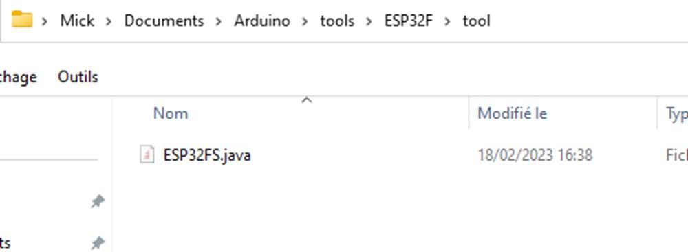
Download plugin .zip file and unzip the content into “tools” folder of your arduino sketch folder (can be found in IDE under File>Preferences) .
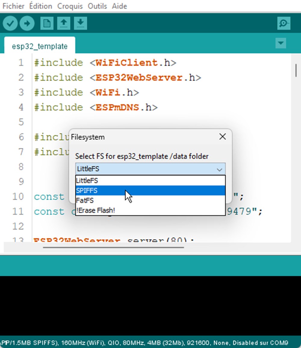
Now the tool is available under Tools> ESP32 sketch Data Upload
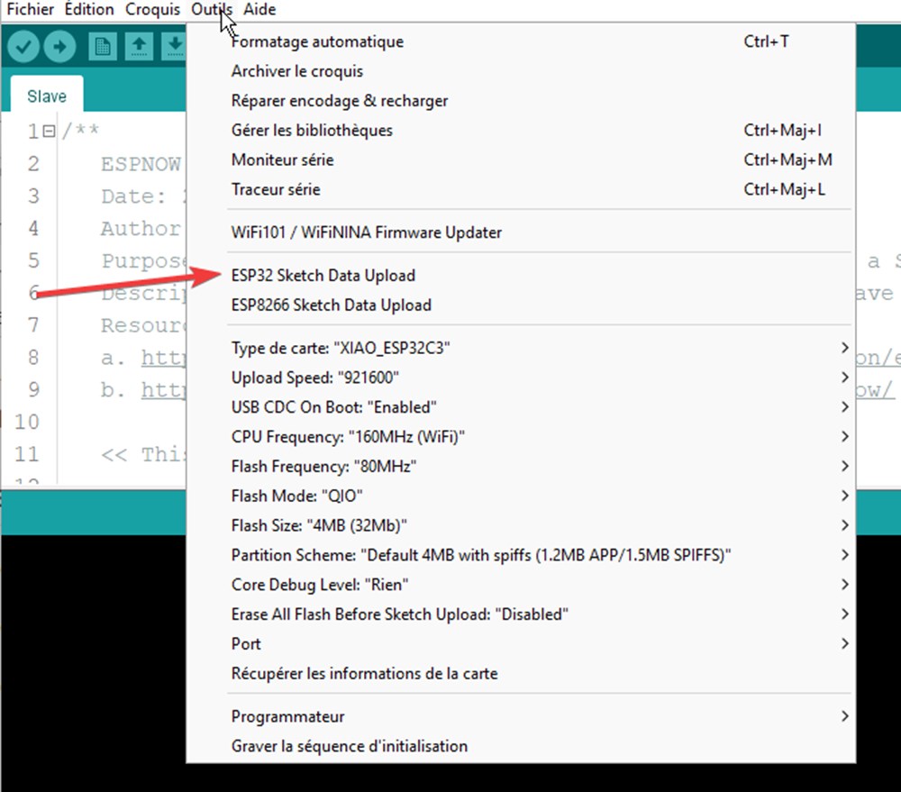
Using this tool, files inside “data” folder of a sketch will be uploaded to SPDIFF filesystem of the ESP32.
Select SPIFFS to start upload.
My template program use WifiManager. This library allow user to easily connect ESP to a Wifi network exhibiting an interface to scan and enter wifi password, without the need to enter/edit them into arduino sketch. https://github.com/tzapu/WiFiManager
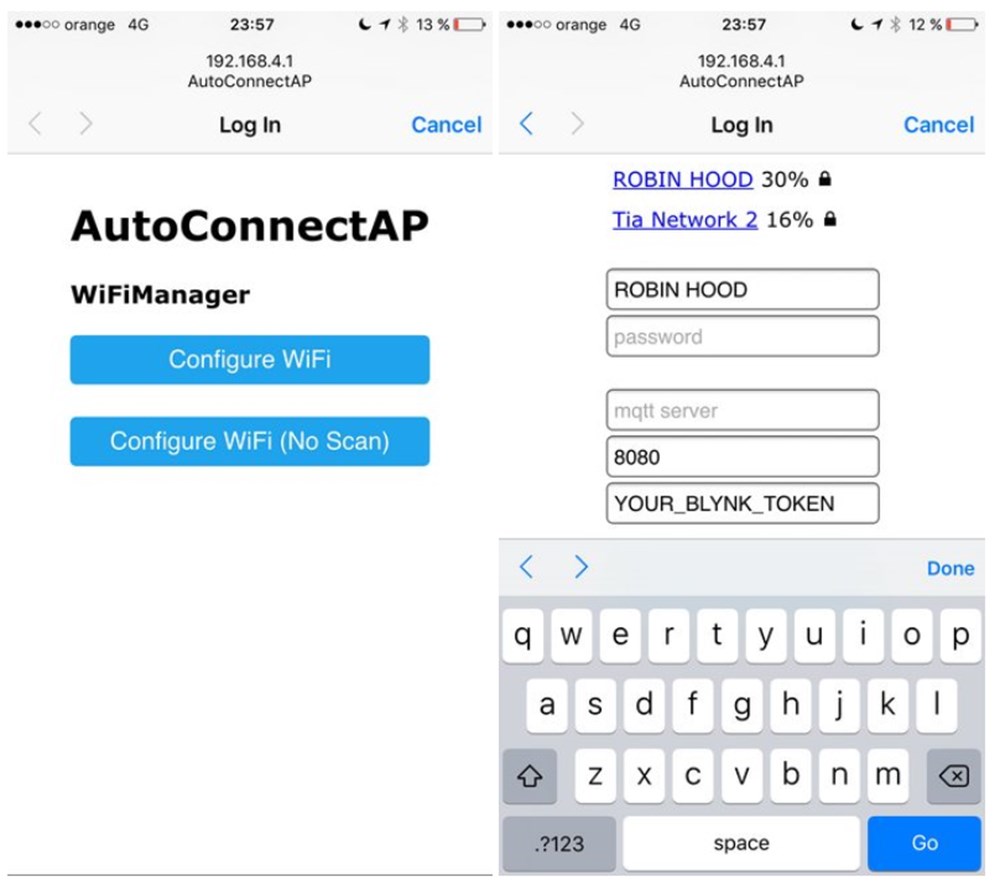
UPDATE: Their is an incompatibilty using WifiManager. It complain about a conflicting wifi.h library
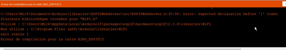
I use another library named ESPAsyncWiFiManager https://github.com/alanswx/ESPAsyncWiFiManager
I found that after a first sketch upload i got an error and it was not possible to make other upload.
Solution seems to be: “some ESP32 boards need to be set manually into bootloader mode. On my board that would be pressing the RESET button and keep it hold, then press the USR button and keep it hold, then release the RESET button, then release the USR button. "
Not very handy….but works
For now Impossible to make this board working reliably.
RP2040
Install RP2040 board support
In File>preferences>Additional cards...
add this line, seperate from other packages with a “,”
https://github.com/earlephilhower/arduino-pico/releases/download/global/package_rp2040_index.json
Then go in tools>Boards>Boards manager and look for “xiao” keyword
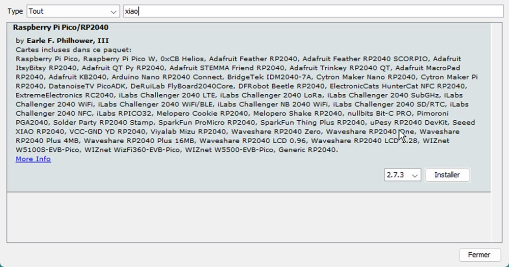
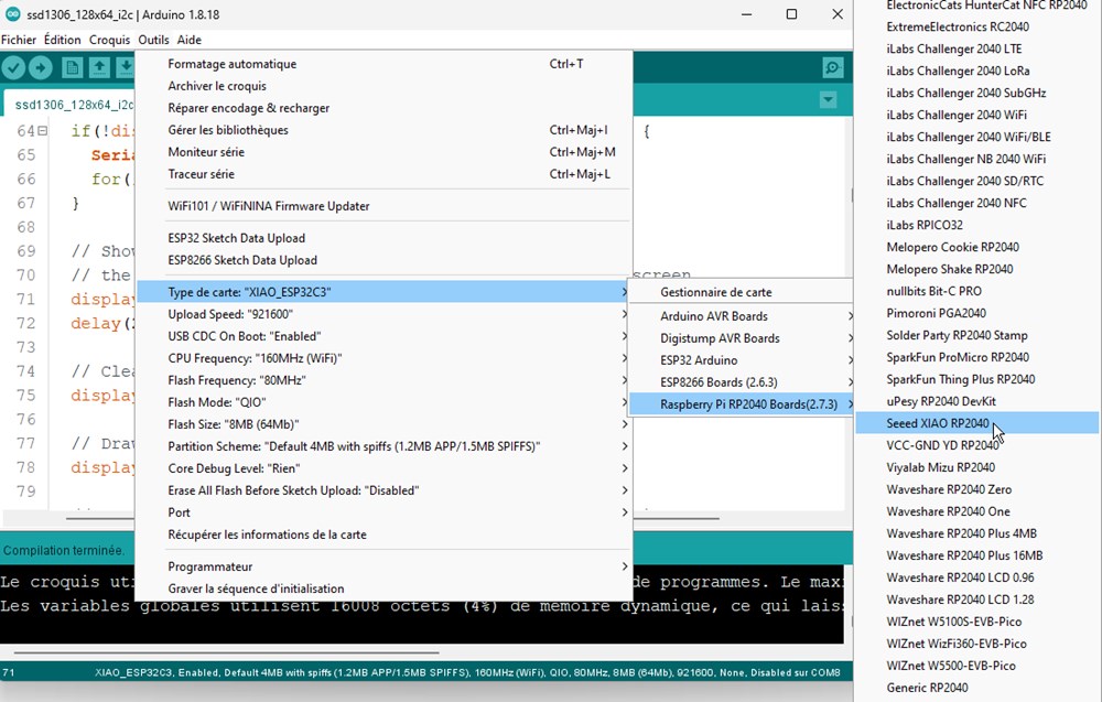
Then select the right board
To control the builtin RGB led, We will include FastLed Library and control the led with this simple code:
MicroPython
https://www.framboise314.fr/demarrer-avec-seeedstudio-xiao-rp2040/
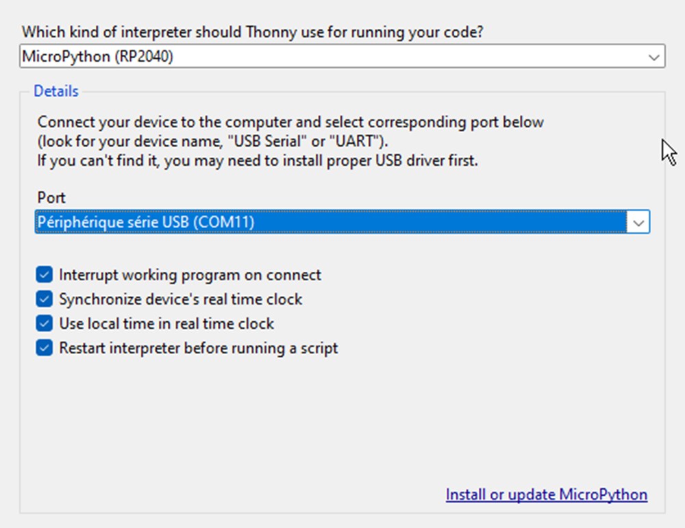
I will use Thonny to use the board with MicroPython. Go to Tools>Options, select RP2040, then the COM port exposed by your board
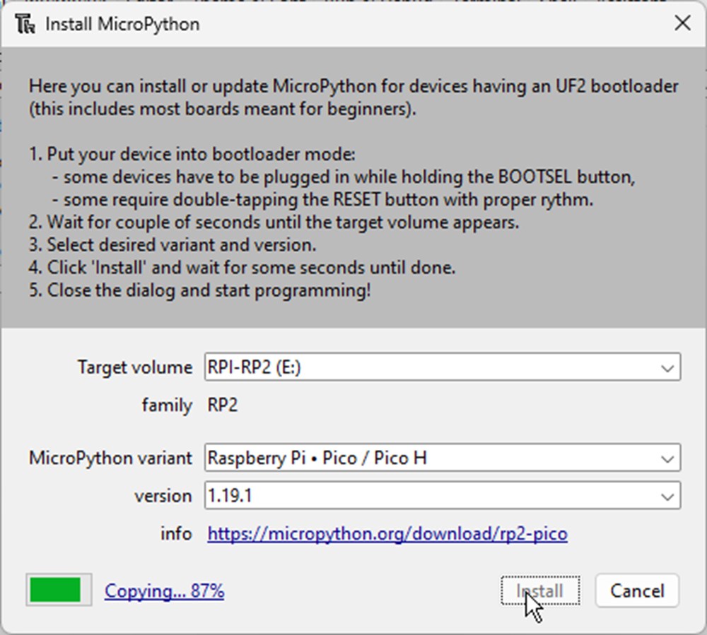
We install MicroPython into the board. First we have to disconnect the com port if open clicking “Stop/restart backend”. Then click on Install or updateMicropython from the above windows. If the board isn’t detected, you can follow those steps:
- Push and hold B button
- Push and hold reset button
- Release B, release Reset
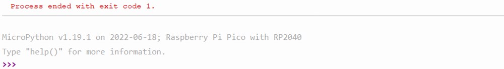
This promp "»>” on the console show that micropython is installed correctly.
Then we can write a python program an click on “run current script” button.
I decided to create a program that can move servomotors in a user defined sequence.
To do so, I first need a servomotor library wich just act as a wrapper aroud PWM standard library. I found it here: https://github.com/pvanallen/esp32-getstarted/blob/master/examples/servo.py
I upload it into the board enabling file explorer on View>Files then, creating a file, right click on it and click “upload to /”
A method “createSequence()” take in arguments a name and a list of servo positions and times.
|
|
test_sequence_1
My first movement sequence will be:
- all servo to position 0
- [0,0,0],[1,0,0],[2,0,0],[3,0,0],[4,0,0]
- one after the other, all servo go to position 180
- [0,180,500],[1,180,700],[2,180,900],[3,180,1100],[4,180,1300]
- wait 2 second then all servo go to 90 at the same time
- [0,90,3300],[1,90,3300],[2,90,3300],[3,90,3300],[4,90,3300]
- all servo go back to 0 one after the other with a 1000ms delay
- [0,0,5000],[1,0,6000],[2,0,7000],[3,0,8000],[4,90,9000]
I nest all those elements into a list and pass it to *createSequence().
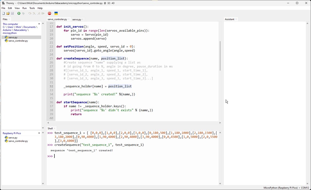
then launch it with: start_sequence(“test_sequence_1”)
start_sequence method loop over the list and move specified servos at specified times.
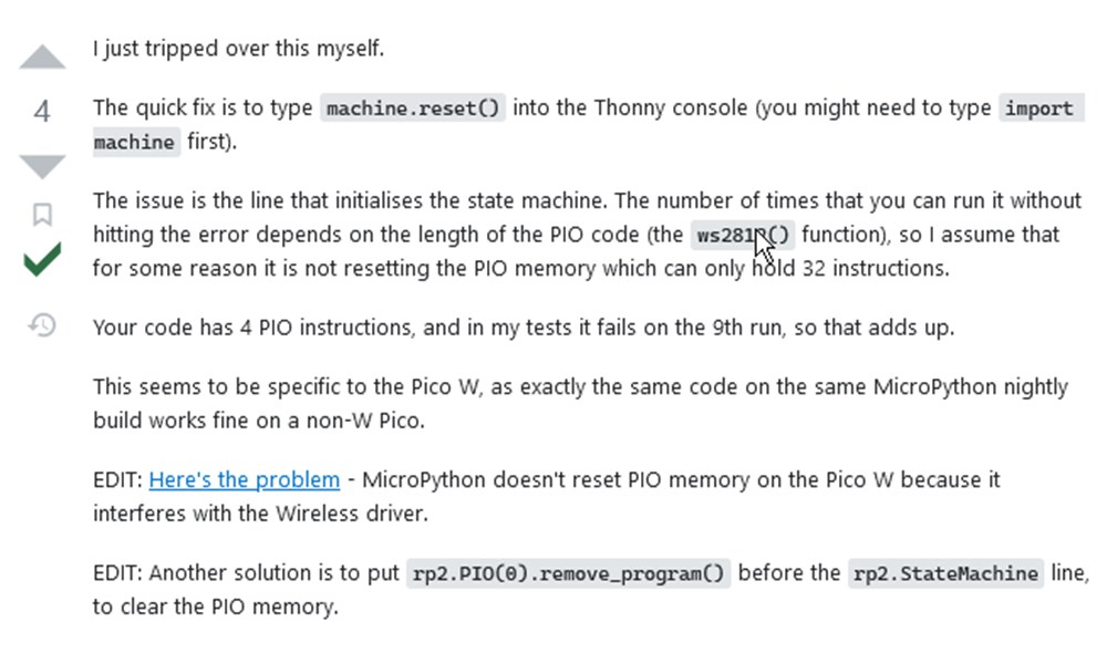
To trigger movement, I first use machine.Timer to call callback method at specific time I got an annoying “[errno 12]: ENOMEM” error.
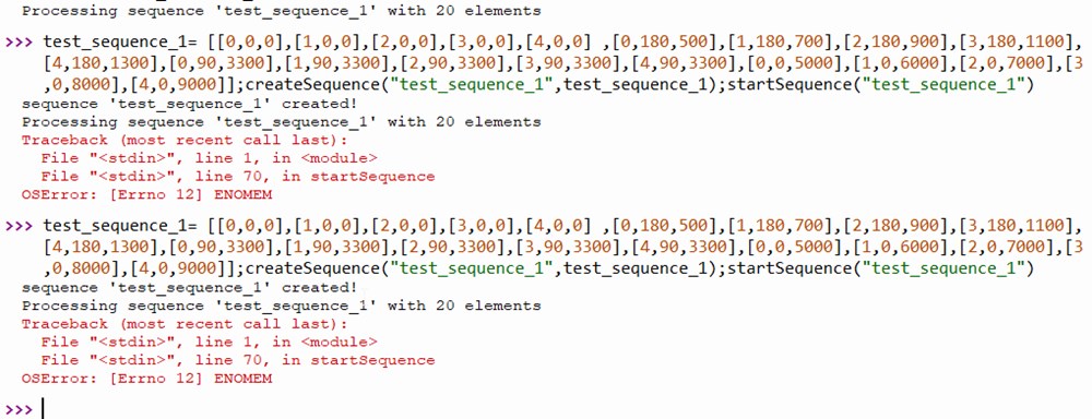 The solution found on stackoverflow was to type machine.reset() in Thonny console
 Then relaunch the script. It seems to works. Finaly, I can’t succeed to make things works with Timer callback. I choose another way checking ellapsed time in a while loop and compare with the parameter start_time of the list.
|
|
Here is a video of the console output. I don’t have an external power supply at home for the servomotors so I can’t record the result for now, but they moves as expected!
Now I could simply generate lists in script to create interesting paterns. For now, I connect 5 servos to an RP2040 board but I will scale it to at least 16 servo using a PWM multiplexer working in I2C like PCA9681 chip or use a raspberry Pi Pico wich have 16 PWM output available.
Add some light
We can use the builtin ws2812 adressable led for example: - confirm reception of a new sequence - blink if an error occur - display a color depending of servo requested position
First, we add the librarie for ws2812 led, we can found it on seedstudio website 
Code
The code related to the light and servo position is bellow. Note that we record the current servomotor position (more precisely, the target position) into an angles list that we use later to update all led colors.
|
|
Then after each call to setPosition() I do a call to update_led_color_from_angles().