Assessments book for this week:
http://fabacademy.org/2023/nueval/computer-controlled_cutting.html
Group assignment
- characterize your laser cutter’s focus, power, speed, rate, kerf, and joint clearance.
- Document your work to the group work page and reflect on your individual page what you learned.
Individual assignments
- Design, lasercut, and document a parametric press-fit
- construction kit, which can be assembled in multiple ways
- Account for the laser cutter kerf
- Cut something on the vinyl cutter
Learning outcomes
- Demonstrate and describe parametric 2D modelling processes.
- Identify and explain processes involved in using the laser cutter.
- Develop, evaluate and construct a parametric construction kit.
- Identify and explain processes involved in using the vinyl cutter.
Have you answered these questions?
- Linked to the group assignment page.
- Explained how you created your parametric design.
- Documented how you made your press-fit kit.
- Documented how you made something with the vinyl cutter.
- Included your original design files.
- Included hero shots of your results.
Usefull links
Some boxes generator for vinyl cut and laser cut: https://www.monfablab.ch/p-generateur-de-boite/ French tutorial: https://www.carinebricole.ch/wp-content/uploads/2016/02/La-Silhouette-decoupe_papier.pdf
Files
Inkscape mookup of all layers: link
Fusion360 model of the tim burton scene: link
Fusion360 model of coardboard box: link
Fusion360 model for the hexagon laser cutted-kit: link
Pebble Packaging
Cardboard box
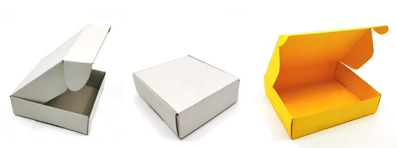
To create the box, I could start from scratch copying a box that I unfold and measure. I redraw it on fusion 360 making width, height and length parametrizable.
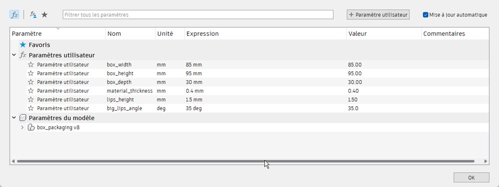
The constrained sketch and extruded result.
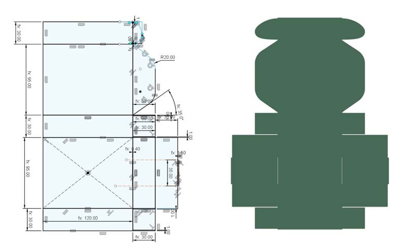
I tryed the design on a 4mm cardboard. After that, I made some adjustement to add offset for the blocking lips (on left and right) and add 1mm on each side. I made another test on 1.2mm thick cardboard (on the right).
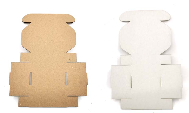
Some trials after folding and changing box width
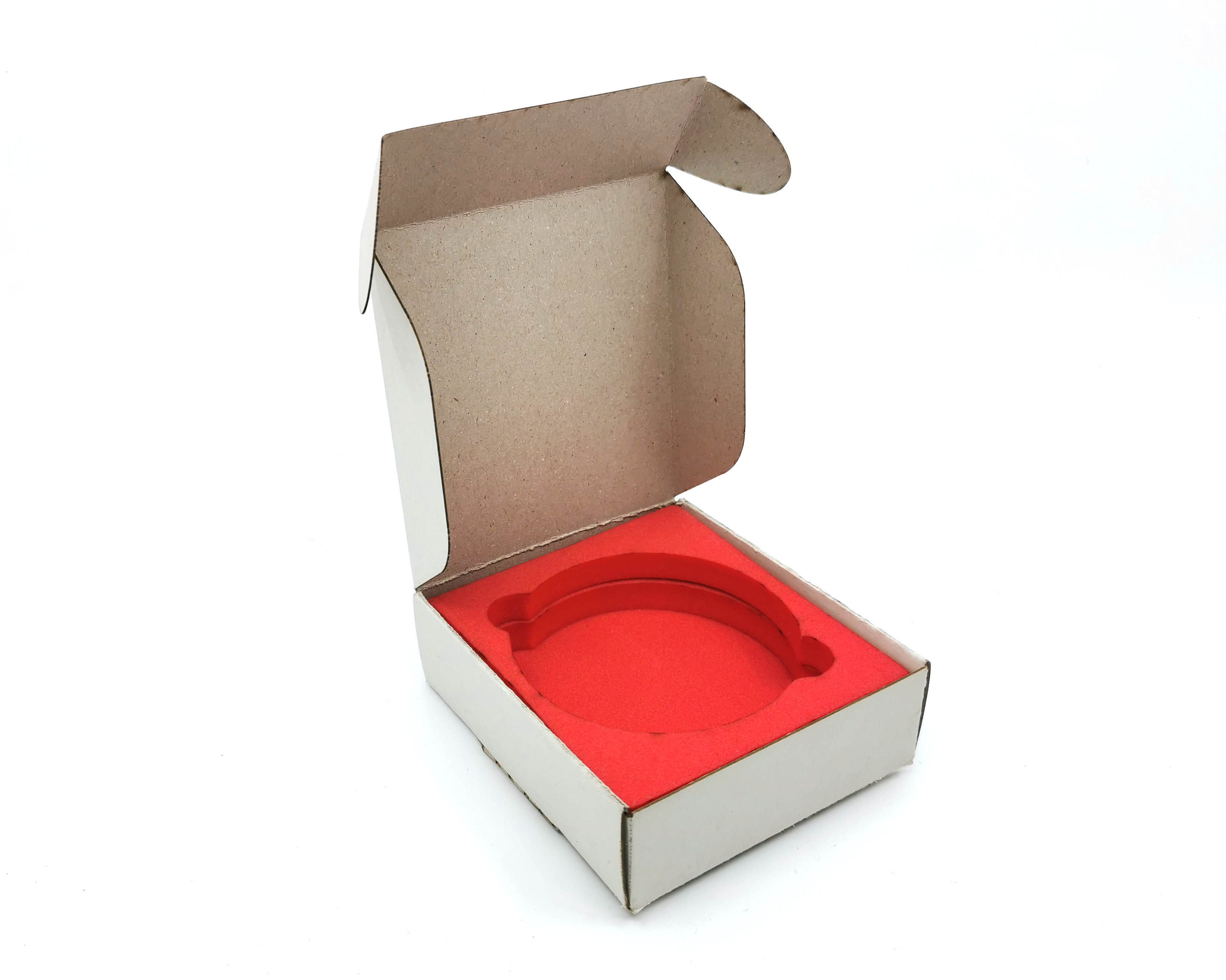
Foam insert
I lasercut some 10mm thick foam to make a confortable bed for the pebble.
And add it inside the box
Snap fit Kit
For the snap-fit assigment,I designed some basic shapes that can matche each other and some connectors to create more complex geometries.
To make insertion easier, I add a rounded shape to the notches
The bigger notches is intended to snap 2 parts together and make a fake 3D shape.
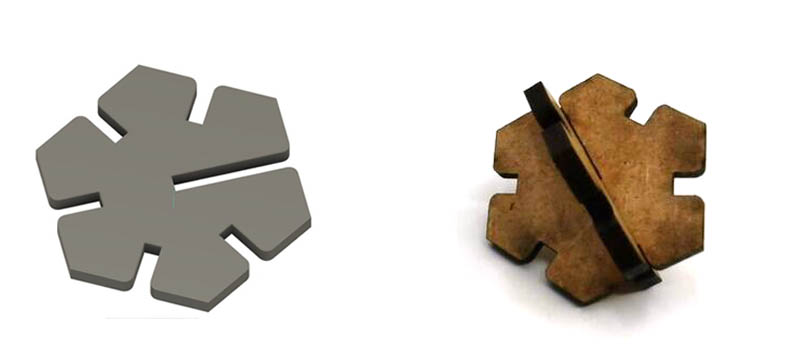
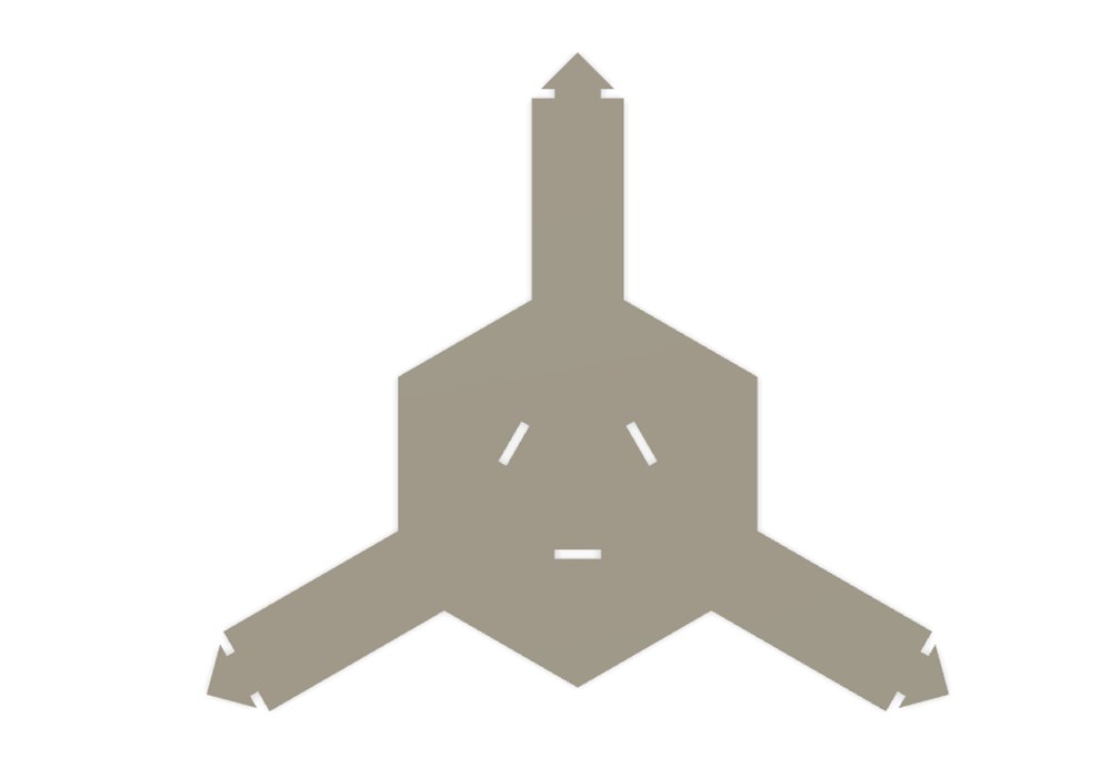
Modular Honeycomb
I tryed another design for the snap-fit assigment. This time I will try laser-cuting on baize.
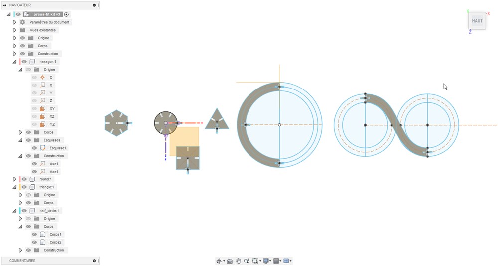
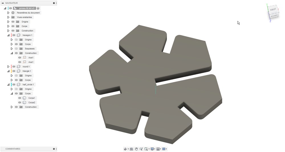
3D design
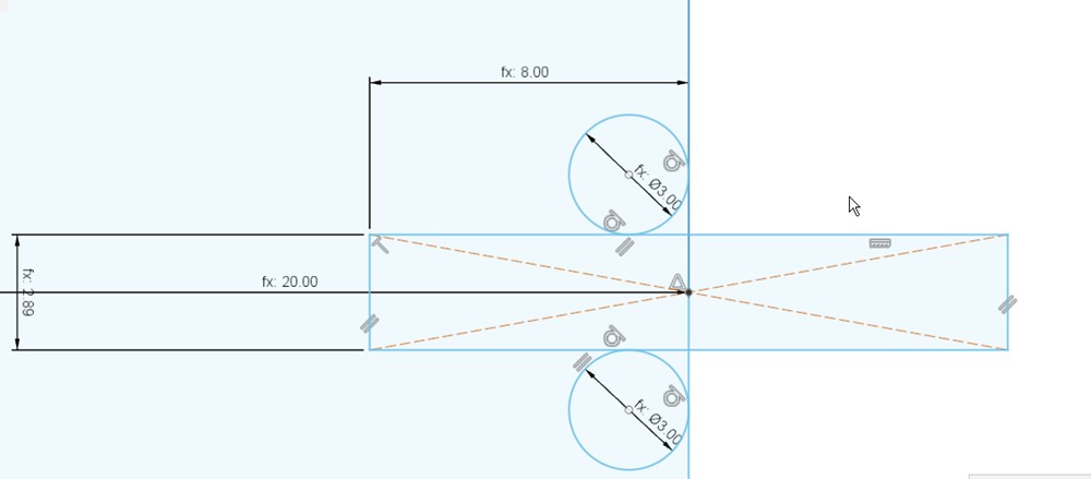
First I create a line, then apply a circular patern with 3 occurence and center at the middle. After that I apply an offset from the center lines in each direction.
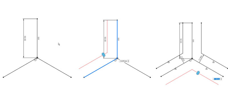
Then I add a centered hexagone, an arrow on the upper side and notches near the center.
![]()
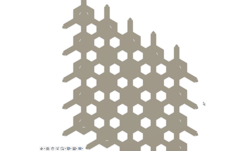
Testing the effect with rectangular patern
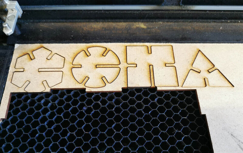
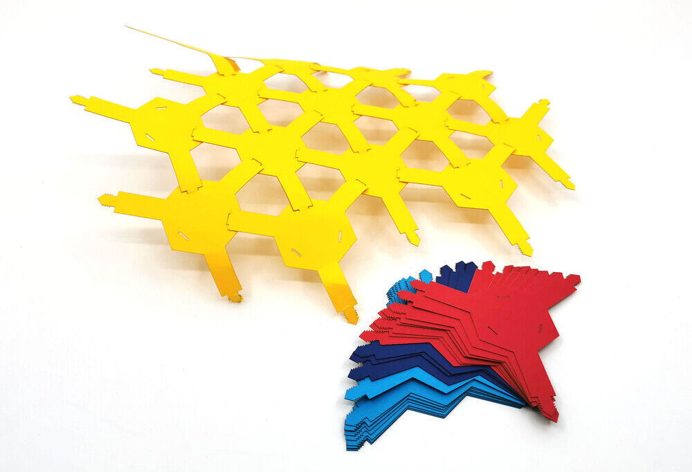
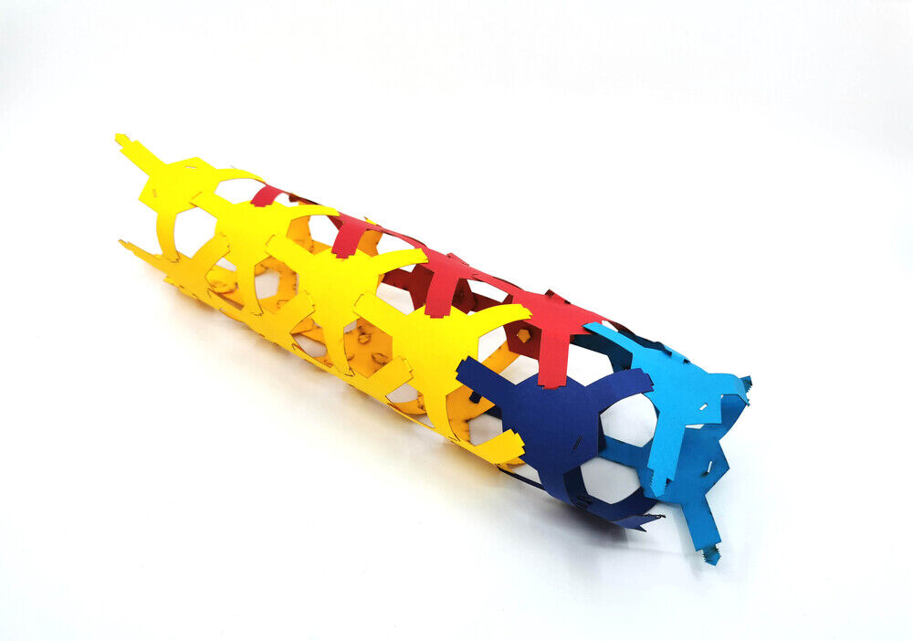
Laser cutting
To make the parts, I choose a cardboard of 0.55mm, after some trials I found those cutting parameters:
- speed: 100%
- power: 55%
After my first cuts, I made some adjustements to the model to make it easier to assemble. First I add more arrows to have a better blocking, then I add a strip to pull easily the insert with fingers when inserting it. This last idea come to my mind only after assembling!

Pebble Mandala
For the top part of the pebble, I give a try to an acrylic specially created for backlight: TroGlass Reverse TG4-400 T 3mm gloss/black We can see on the right image that it is made with a thin layer of black material on one face of an transparent acrylic sheet. This material is vaporised by the laser and reveal the underlying surface.
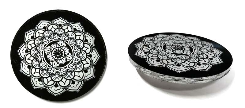
The result is pretty nice. The problem is that it is flat and my top layer need to be curved. We will try to solve this later!
TODO:
- Test on glass with black painting
- Test on glass or plexi with inverse engraving then paint inclusion
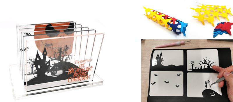
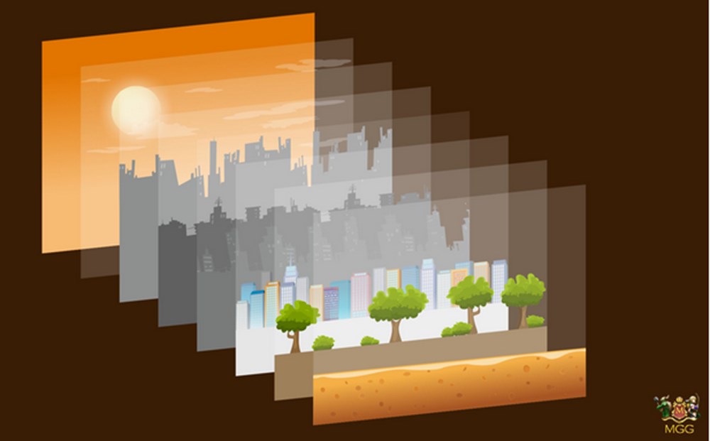
Laser and vinyl cutting: Paralax background
Introduction
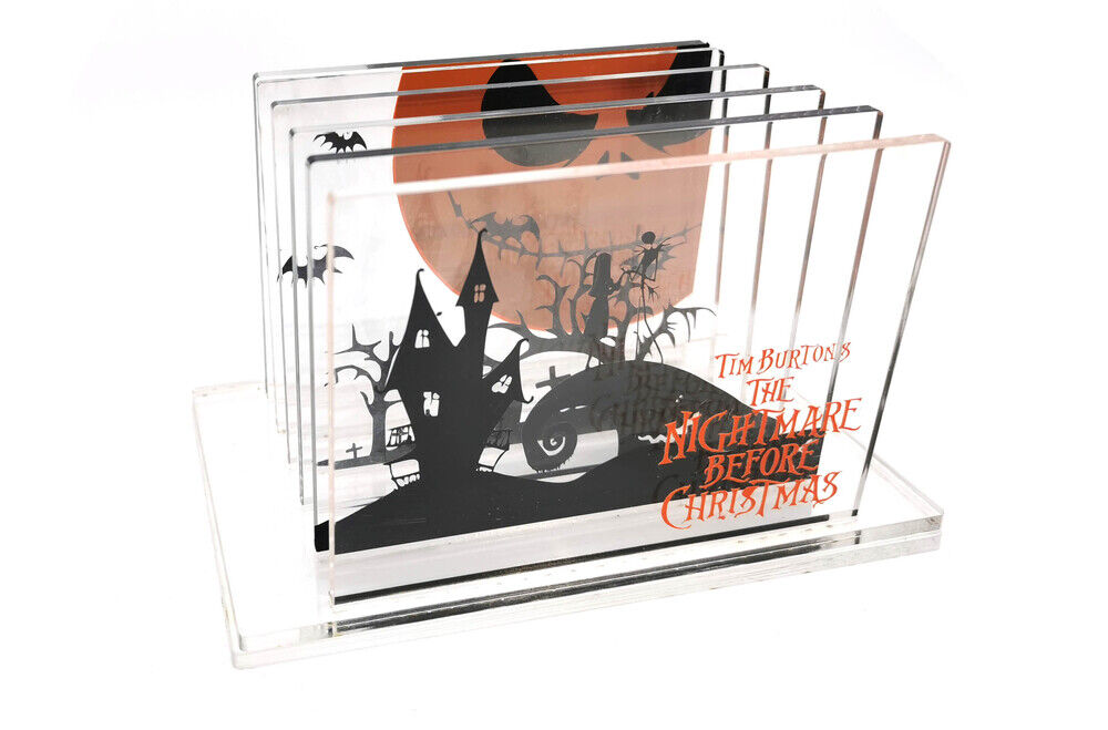
To combine laser cutting and vinyl cuter, I will make a sliced background like this “paralax background”. I will create a base on wich I will put 6 differents plexiglass slices with vinyl cutted graphics sticked on them.
Plexiglass support
First I create a base in Fusion 360 to hold the different slices.
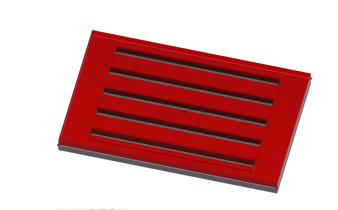
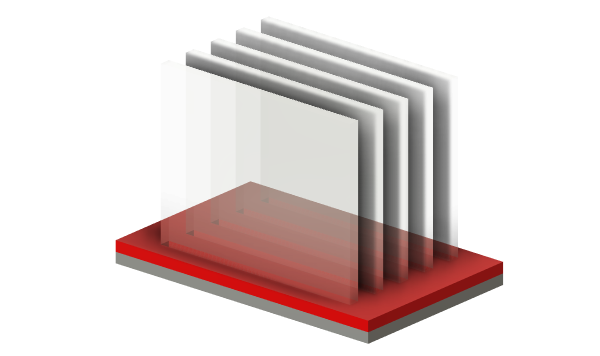
I will cut all parts in 3mm plexiglass. The base will be made with two layers, one with notches for the vertical slices.
Graphic part
I will use black and orange vinyl on my silhouete cameo 3 vinyl cutter. I will then transfer the drawing to each layer.
An inspiration for the graphics:
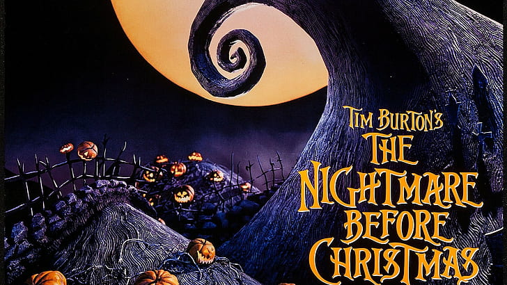
I found it online on a wallpaper website: lien
As i am not a good artist, I will not try to redraw fro scratch, so all the images used below are taken from internet, adjusted/modified in photoshop and vectorized in Inkscape.
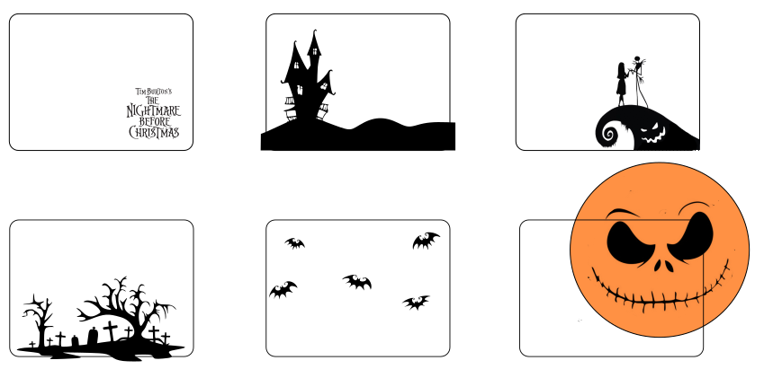
As vinyl is monochrome, I have to find, or create, only black and white “shadow puppet” style images. For that I found differents images on internet, then vectorize them with Path > Vectorize a matricial image tool in inksape.
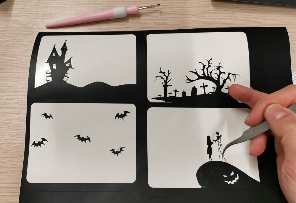
I create 6 different layers in Inskape
- Title Layer in orange
- Landscape and house in black
- 2 characters on a wave in black
- Cimetary background in black
- Bats in black
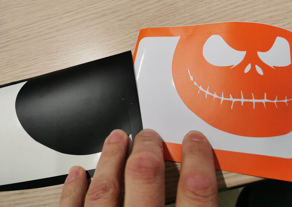
- The moon in orange and black
For the last layer, I will overlap a black round with an orange layer to obtain a bicolored effect.
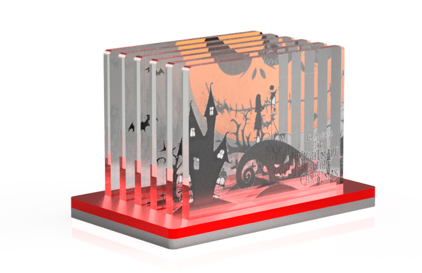
Simulation
To simulate the object appearence, I use fusion 360 rendering section after adding “decals” on each plexiglass layer. The image are copied from Inkscape to transparent png before using them.
Vinyl cutting
Now let’s cut it! With my first test, I realize that it will be difficult to create too small text, I increase the size a little bit and adjust Cameo3 cutting parameters.
- Depth: 2
- Force: 2
- Speed: 10
Text too small, complete fail
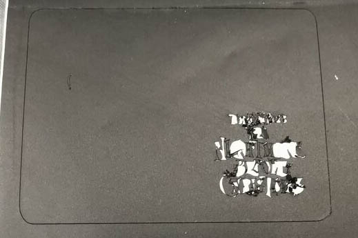
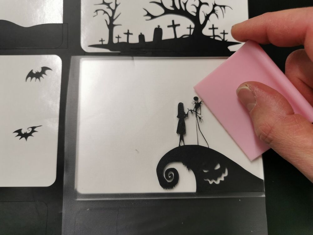
Even after enlarging it, small part of the text don not separate from the vinyl sheet. I finally found a way to use it anyway sticking the whole vinyl on acrylic then remove the excess by hand or with a needle for smaller part.
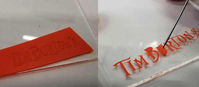
Hoppefully, for bigger graphic I can use the more classic transfer paper method.
The 2 parts of the moon layer, ready to be overlapped.
Done!
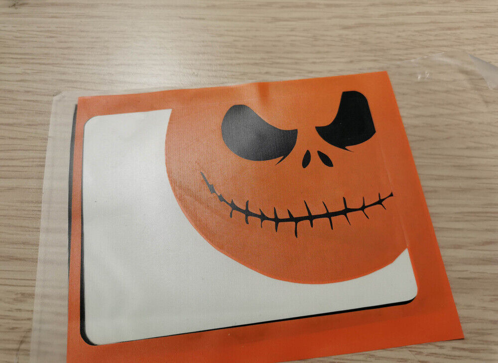
I remove the excedent parts of the graphic with a tweezer …
…Then transfer it on acrylic.
And the final result!
Vinyl cutting for fabric transfer
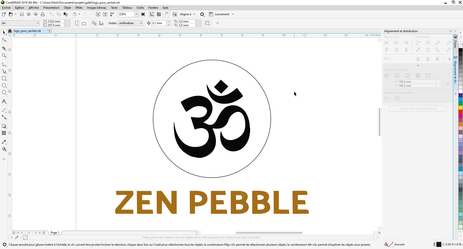
I design on CorelDraw a simple logo in order to transfer it on fabric bag to store my final project
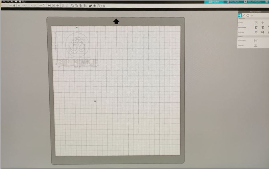
I export it to DXF and import it into Silhouette studio software. I adjust the size to fit on my fabric bag. Then I go to “Send tab” and launch the cut.
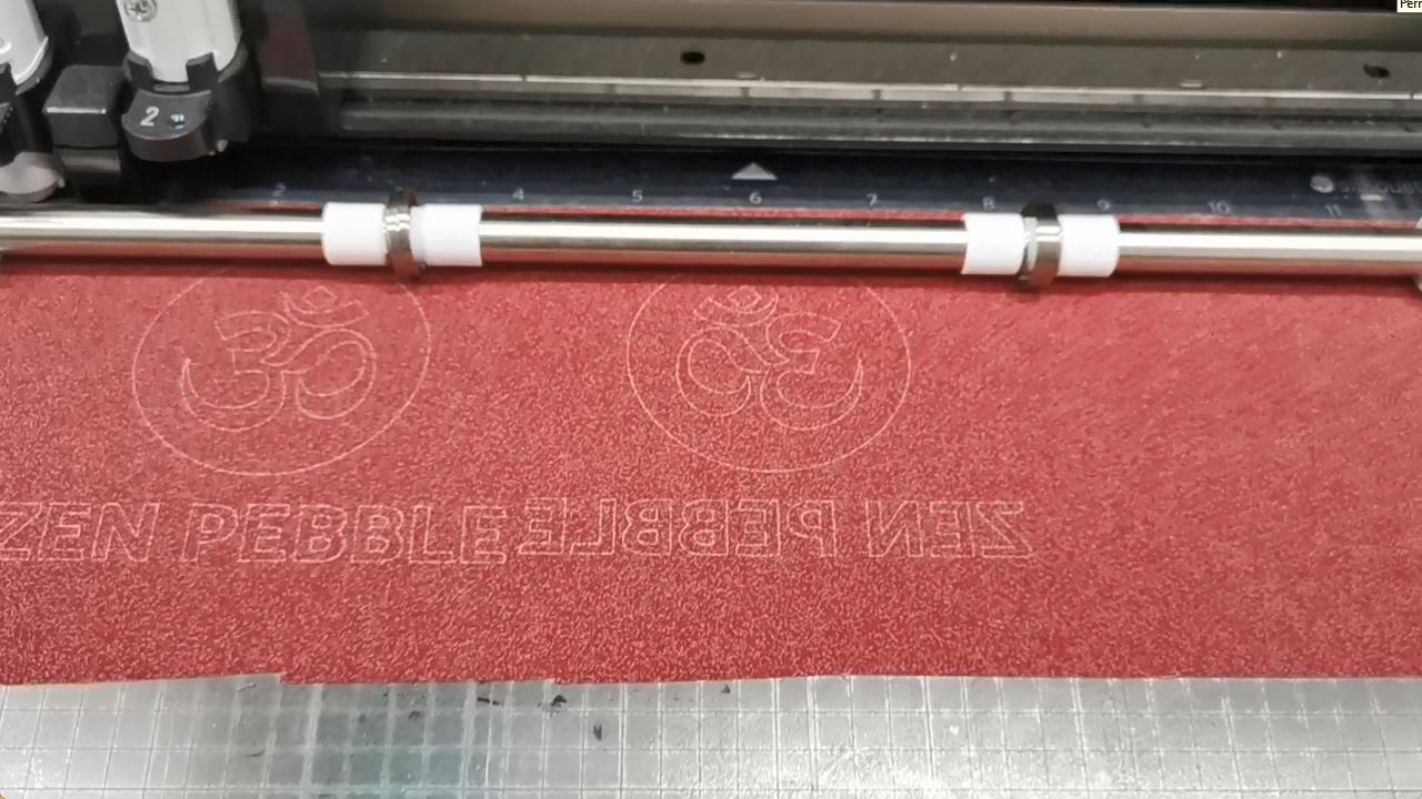
After removing unwanted material, I apply the plastic on fabric (no transfer tape needed for this material and the design has to be mirrored)
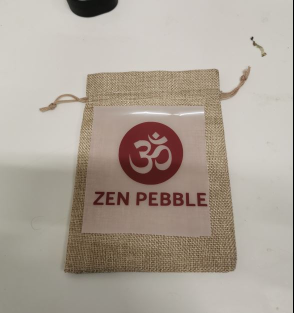
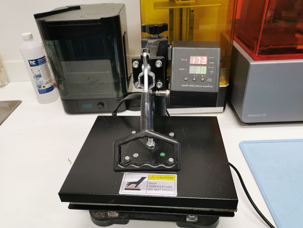
I put it under the heat press, at 180°C for 30 seconds
Laser cutter caracterisation
Power speed grid
I will create some calibration cards using a template found on another FabAcademy student as a base: http://fabacademy.org/2021/labs/barcelona/students/nil-peguero/Material_template.ai
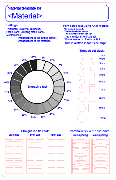
I made a few adjustements for my needs, remove flex cut part and adding speed/power test. On epilog mini, we can create color - (speed-power) correpondence on the machine driver. Epilog mapping instructions: https://www.epiloglaser.com/epilogfiles.com/color_mapping_instructions.pdf
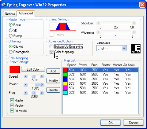
As I want to test a lot of speed/power combinaison, It would have been tedious to create some much profile. I prefer to cheat using a non ‘hairline’ line and apply a grayscale gradient to change linearly the laser power.
- Set “engraving power” to 100%
- Set “engraving speed” to min value (10%)
- Keep only one line on the file
- Repeat 10 times with 10 successive lines increasing speed manually at each iteration
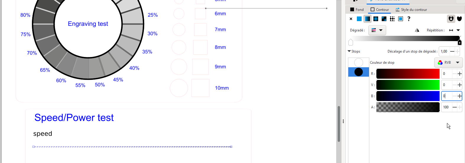
I create a line with a 0,265 thickness and apply a gradient from white to black to it.
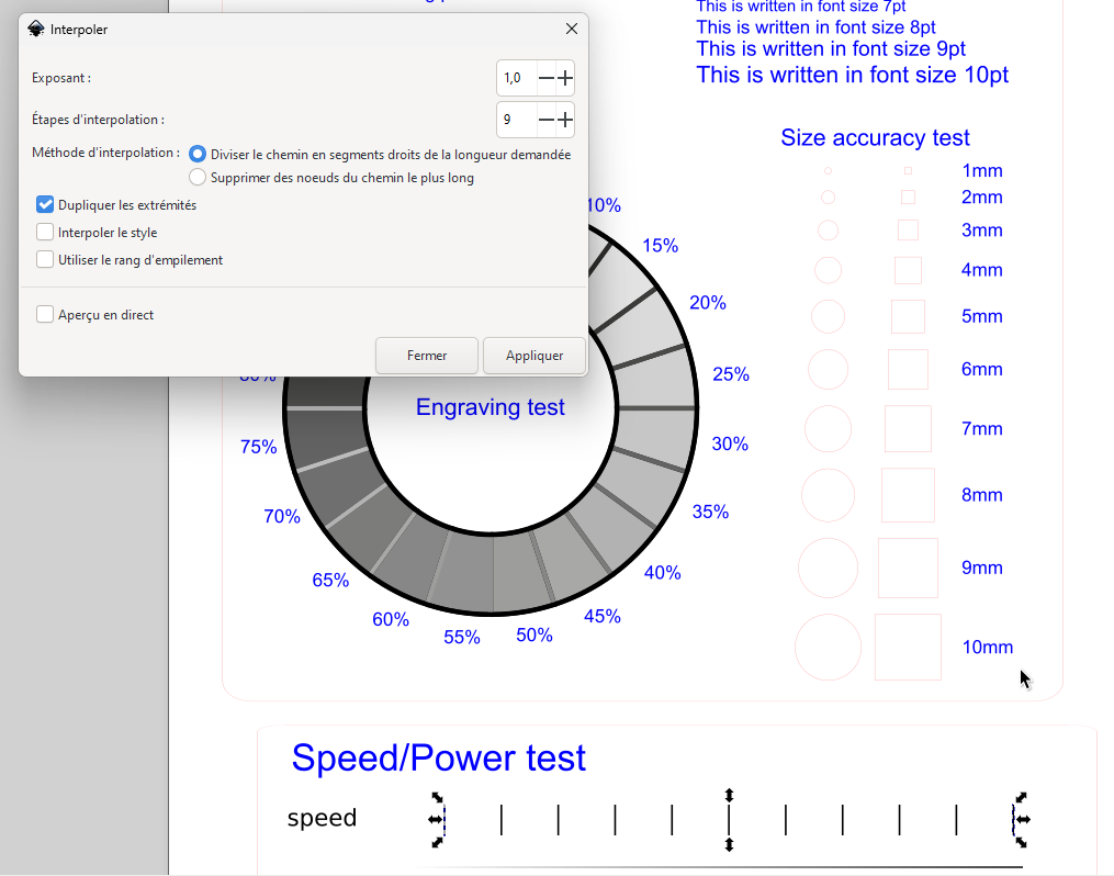
I create a ruler with a first and last vertical line. Then on Extensions > Generate from path > Interpolate and choose 9 interpolation steps.
Resulting speed/power test template
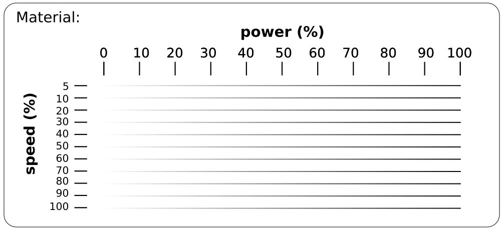
*NOTE: I haven’t had time to test this! I am not even sure that this technic to use ’engraving mode" to test cutting work as i imagine
Kerf measurement
To determine the Kerf of the laser cutter, we will use and compare 2 methods:
- Divide a rectangle into 10 segments of 10mm. Measure the resulting parts with a caliper and compare with the size of the rectangle. Kerf will be equal to DIFFERENCE_IN_SIZE/(10+1)
- Draw a single line and measure directly with a microscope
Results
Caliper method
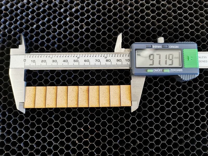
10 segments mesure in total 97.19mm -> kerf = (100 - 97.19) /11
kerf on 3mm mdf = 0,255mm
Microscope method
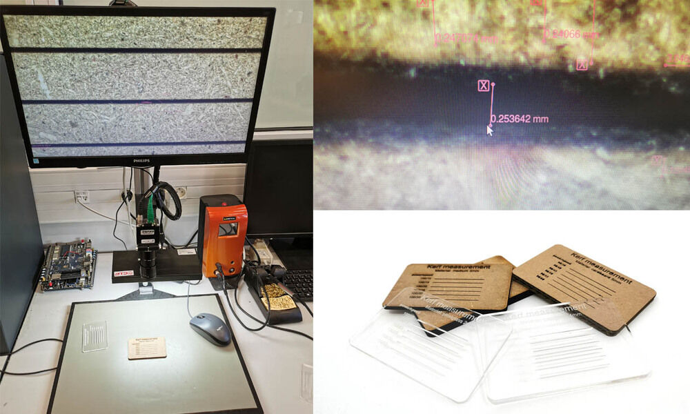
I found a prety close result of 0.253mm. We see with the miscroscope that the kerf is not consistant along the whole line. We should avergare several measurements to be more precise. For the snapshot, I have to admit that I choose the best matching result!