Potentiometer, probe on middle pad, ground and 5V on other pads:
Joystick
Now signal from a analog joystick, one probe on x axis, the other on y. Those joystick are simply one potentiometer for x axis, another for y axis and a button for click detection.
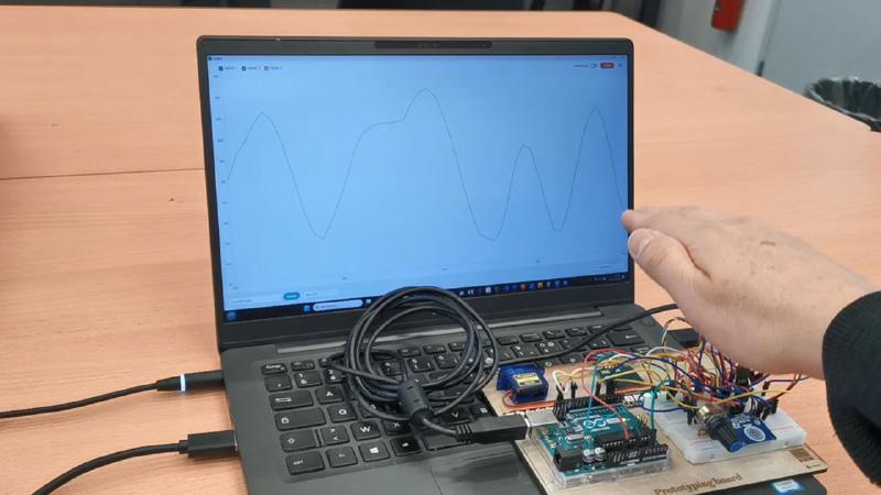
Time Of Flight sensor
I connect a VL53V0X time of flight sensor to an arduino uno through i2c (SDA and SCL pins). Then I simply print the distance to serial and display it in realtime with the serial plotter tool of the Arduino IDE.
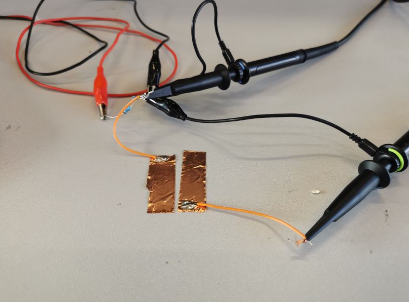
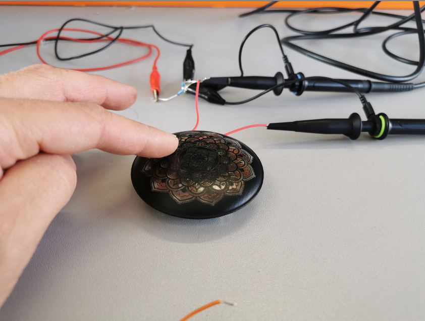
Step response as touch sensor
I cut and connect 2 copper adhesive to an oscilloscope following Robert Hart’s tutorial and Neil’s examples.
Instead of using a microcontroler to read the signal I do it with an oscilloscope on one of the tape and connect a signal generator on the other one.
The generator output a square signal with 5V amplitude and 100Mhz frequency.
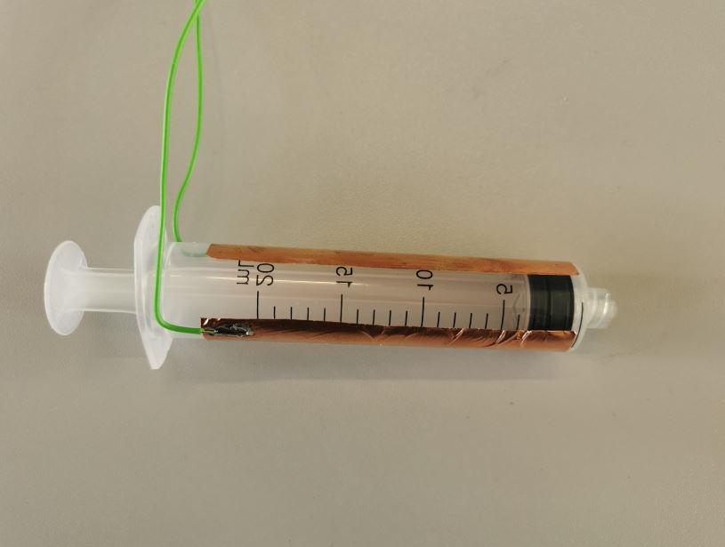
Step response as liquid volume detector
Now, with the setup signal generator and oscilloscope setup, I place the 2 electrodes on a syringe and check the signal when filling and unfilling it with water.
Multiple area touch sensor
For my final project, I would like to include a step reponse sensor array to detect simple gesture as wiping left/right and rotation, covering the whole surface of my pcb.
Code
The code for step response sensor is based on this one:
//tx_rx03 Robert Hart Mar 2019.
// Program to use transmit-receive across space between two conductors.
// One conductor attached to digital pin, another to analog pin.
//
// This program has a function "tx_rx() which returns the value in a long integer.
//
// Optionally, two resistors (1 MOhm or greater) can be placed between 5V and GND, with
// the signal connected between them so that the steady-state voltage is 2.5 Volts.
//
// Signal varies with electric field coupling between conductors, and can
// be used to measure many things related to position, overlap, and intervening material
// between the two conductors.
//
longresult;//variable for the result of the tx_rx measurement.
intanalog_pin=A3;inttx_pin=A1;voidsetup(){pinMode(tx_pin,OUTPUT);//Pin 4 provides the voltage step
Serial.begin(9600);}longtx_rx(){//Function to execute rx_tx algorithm and return a value
//that depends on coupling of two electrodes.
//Value returned is a long integer.
intread_high;intread_low;intdiff;longintsum;intN_samples=100;//Number of samples to take. Larger number slows it down, but reduces scatter.
sum=0;for(inti=0;i<N_samples;i++){digitalWrite(tx_pin,HIGH);//Step the voltage high on conductor 1.
read_high=analogRead(analog_pin);//Measure response of conductor 2.
delayMicroseconds(100);//Delay to reach steady state.
digitalWrite(tx_pin,LOW);//Step the voltage to zero on conductor 1.
read_low=analogRead(analog_pin);//Measure response of conductor 2.
diff=read_high-read_low;//desired answer is the difference between high and low.
sum+=diff;//Sums up N_samples of these measurements.
}returnsum;}//End of tx_rx function.
voidloop(){result=tx_rx();Serial.println(result);//delay(100);
}
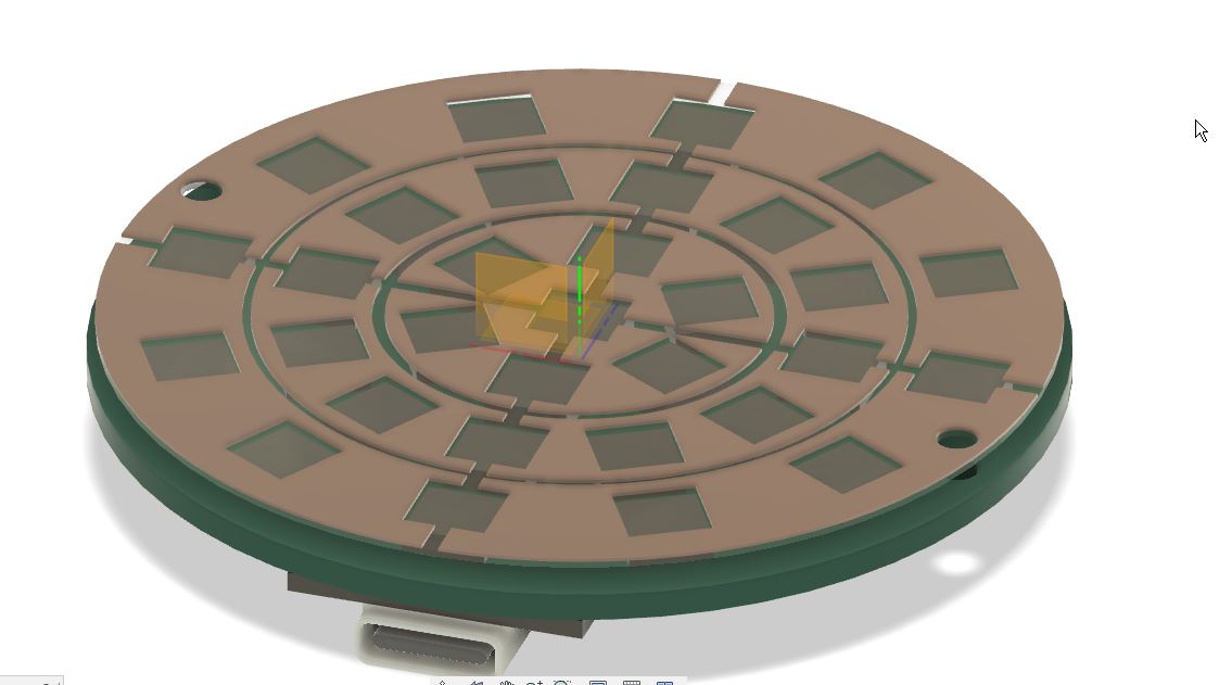
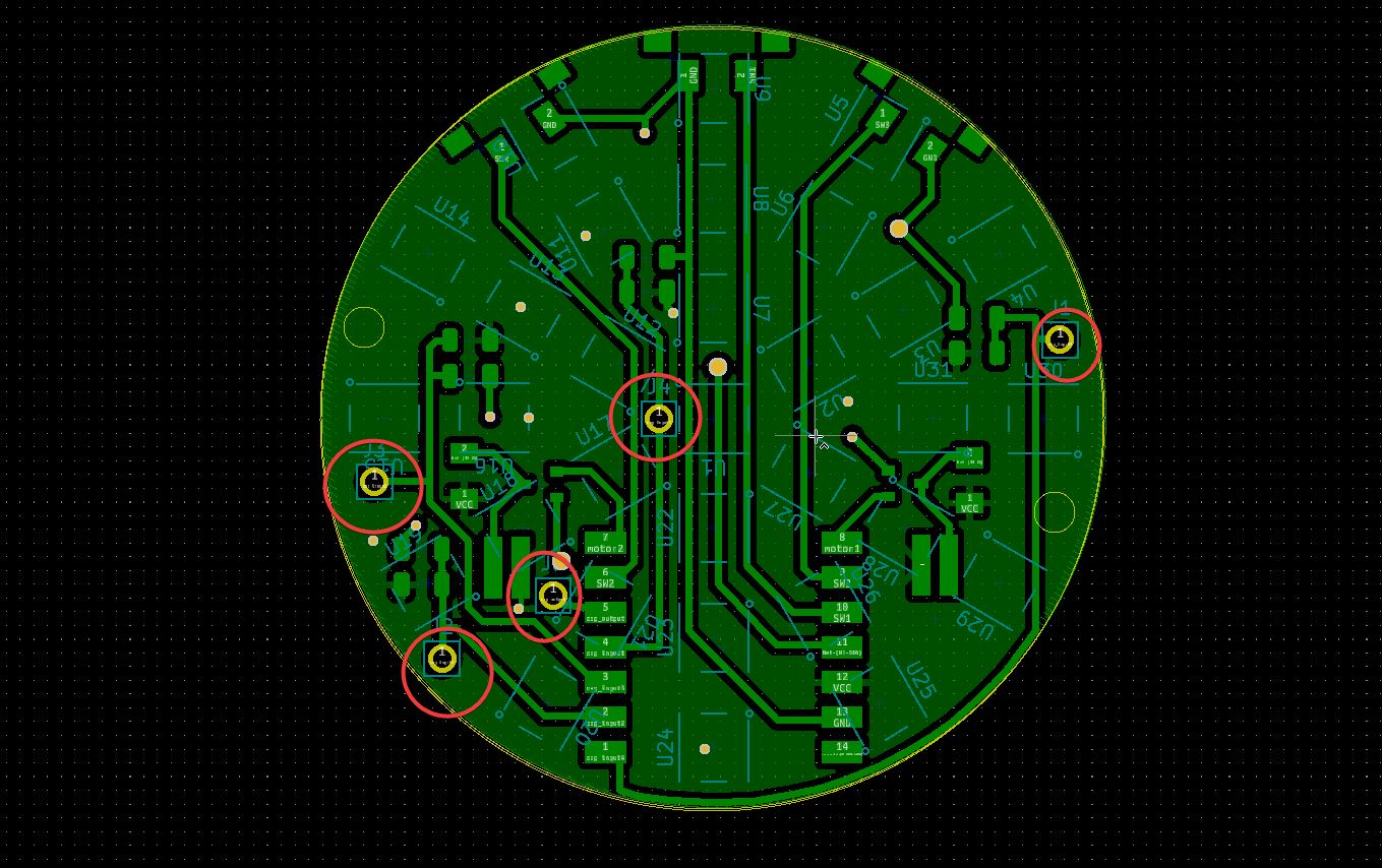
Sensor design
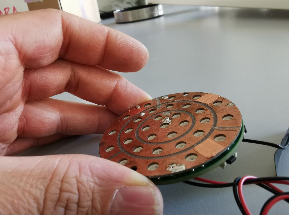
To do so, I design a layer of copper with multiple areas and holes to let the LEDs light pass through. I design this layer into Fusion 360.
1
2
I then export a 2D view as a DXF file. To do so, right click on the sketch use to create the 3D model and “export as dxf” or right click>Create drawing" then project the top face at 1:1 scale and export as pdf.
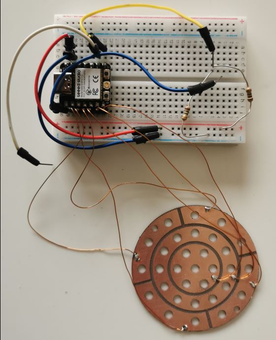
I made 2 trials, one with the vinyl cutter on copper tape and another by engraving and cutting a blank pcb board.
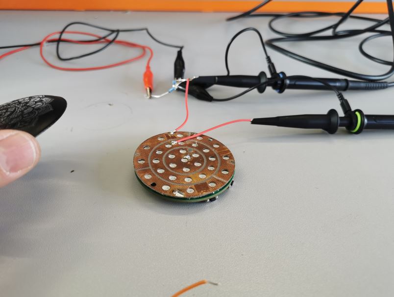
First, I test the setup on breadboard
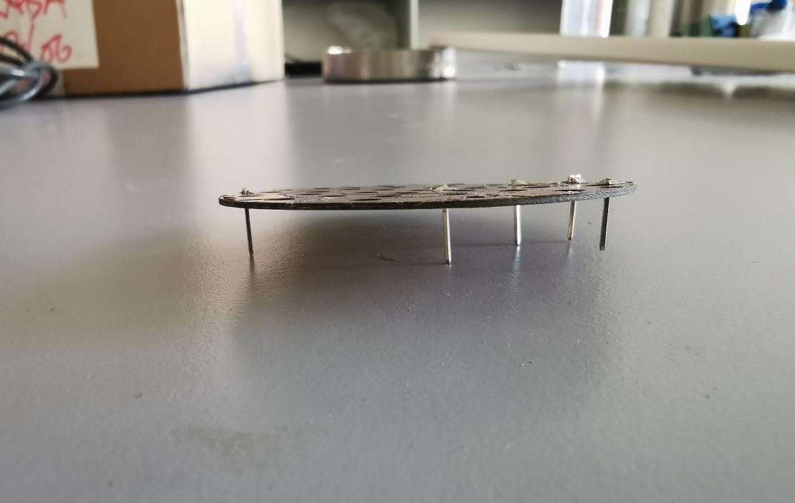
Then I soldered some pins header on the capacitive layer to connect it to my final project PCB.
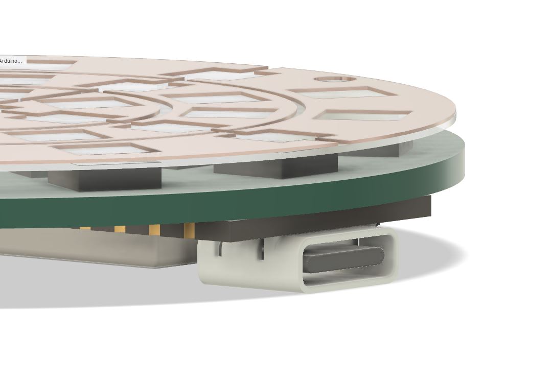
Capacitive layer solder to my final project pcb, on top of the leds.
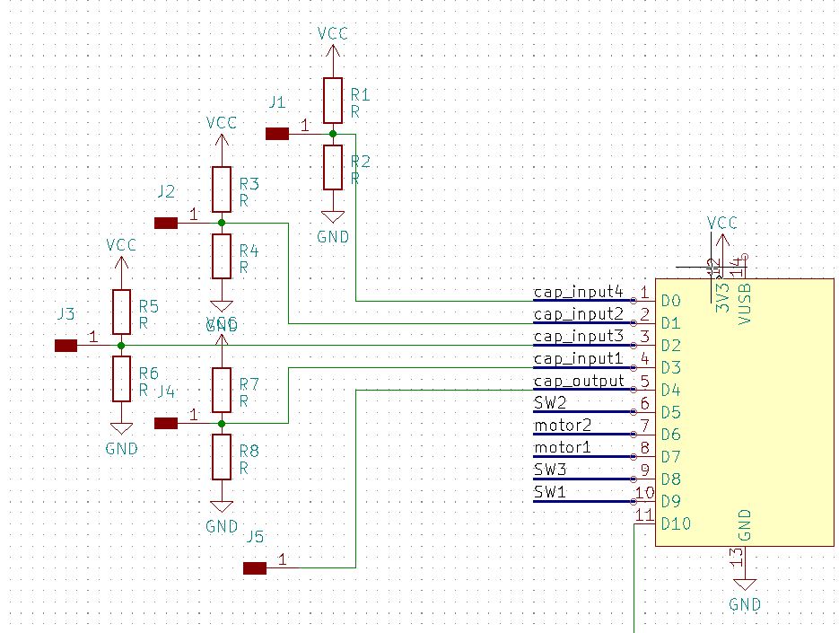
Schematic of the 4 input and 1 output connected to the microcontroler. J1 to J4 are holes intendeed to connect the sensor layer with male pinheaders.
#define CAP_INPUT_1 D3// D3 is ADC2, CONFLICTING WITH WIFI
#define CAP_INPUT_2 D1
#define CAP_INPUT_3 D2
#define CAP_INPUT_4 D0
#define CAP_OUTPUT D4
longintcap_array_values[4]={0,0,0,0};voidsetup(){pinMode(CAP_OUTPUT,OUTPUT);}voidloop(){tx_rx_all_channels(sum);//we pass sum (array adress), it will be modified inside method
for(inti=0;i<4;i++){Serial.print(cap_array_values[i]);if(i!=3)Serial.print(",");}Serial.println();}voidtx_rx_all_channels(longint*sum){//Function to execute rx_tx algorithm and return a value
//that depends on coupling of two electrodes.
//Value returned is a long integer.
intread_high[4];intread_low[4];intdiff[4];intpin_ids[4]={CAP_INPUT_1,CAP_INPUT_2,CAP_INPUT_3,CAP_INPUT_4};intN_samples=100;//Number of samples to take. Larger number slows it down, but reduces scatter.
for(inti=0;i<4;i++)sum[i]=0;//Reset
for(inti=0;i<N_samples;i++){digitalWrite(CAP_OUTPUT,HIGH);//Step the voltage high on conductor 1.
read_high[0]=analogRead(pin_ids[0]);read_high[1]=analogRead(pin_ids[1]);read_high[2]=analogRead(pin_ids[2]);read_high[3]=analogRead(pin_ids[3]);delayMicroseconds(100);//Delay to reach steady state.
digitalWrite(CAP_OUTPUT,LOW);//Step the voltage to zero on conductor 1.
read_low[0]=analogRead(pin_ids[0]);read_low[1]=analogRead(pin_ids[1]);read_low[2]=analogRead(pin_ids[2]);read_low[3]=analogRead(pin_ids[3]);//desired answer is the difference between high and low.
for(intj=0;j<4;j++){diff[j]=read_high[j]-read_low[j];}//Sums up N_samples of these measurements.
for(intj=0;j<4;j++){sum[j]+=diff[j];}}}
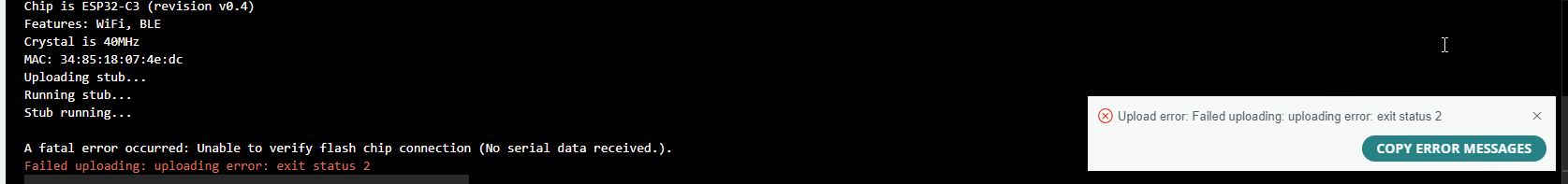
Coding and upload problem
During development, I upload a faulty code using pointers in my arduino code. It ended up by blocking the device (reseting constantly) and I wasn’t able to upload anymore.
I was ready to use a new esp board, hopefully, I follow a trick from this page that unlock the situation.
1
2
3
4
5
6
-Createanemptysketchwithadebuglineintheloop.SomethinglikeSerial.println("debug line");.ItriedtouploadthiscodeandconnectviaSERIALtoseeifitwasuploadedcorrectly.-Uploadthecodedirectlyfromesptool.py.AsIprogramitfromthearduinoide,theeasiestwayistoactivatetheuploaddebugintheide.File>preferences>"Show detailed output while">"Upload".-Uploadthesketchfromthedebugline.Itwillgeneratetheerror"A fatal error occurred: Unable to verify flash chip connection (No serial data received.)."ButatthetopofthearduinoIDEconsoletheexecutedesptool.pycommandwillappear.Somethinglikethis:`LasvariablesGlobalesusan48428bytes(14%)delamemoriadinámica,dejando279252bytesparalasvariableslocales.Elmáximoes327680bytes.C:\Users\user\AppData\Local\Arduino15\packages\esp32\tools\esptool_py\4.5.1/esptool.exe--chipesp32s3--portCOM3--baud115200--beforedefault_reset--afterhard_resetwrite_flash-z--flash_modedio--flash_freq80m--flash_size8MB0x0C:\Users\user\AppData\Local\Temp\arduino_build_393730/MySketch.ino.bootloader.bin0x8000C:\Users\user\AppData\Local\Temp\arduino_build_393730/MySketch.ino.partitions.bin0xe000C:\Users\user\AppData\Local\Arduino15\packages\esp32\hardware\esp32\2.0.9/tools/partitions/boot_app0.bin0x10000C:\Users\user\AppData\Local\Temp\arduino_build_393730/MySketch.ino.binesptool.pyv4.5.1SerialportCOM3`-Copythecommandandrunit,addingthe**--no-stub**parameteratthebegining.Thiswillallowtouploadthenewsketch.WiththisyoucanuploadsketchesfromthearduinoIDEagain.Inmycasewas:`C:\Users\user\AppData\Local\Arduino15\packages\esp32\tools\esptool_py\4.5.1/esptool.exe--no-stub--chipesp32s3--portCOM3--baud115200--beforedefault_reset--afterhard_resetwrite_flash-z--flash_modedio--flash_freq80m--flash_size8MB0x0C:\Users\user\AppData\Local\Temp\arduino_build_393730/MySketch.ino.bootloader.bin0x8000C:\Users\user\AppData\Local\Temp\arduino_build_393730/MySketch.ino.partitions.bin0xe000C:\Users\user\AppData\Local\Arduino15\packages\esp32\hardware\esp32\2.0.9/tools/partitions/boot_app0.bin0x10000C:\Users\user\AppData\Local\Temp\arduino_build_393730/MySketch.ino.bin`
Problem with ADC_2
It seems that D4 pin is not usable when wifi is enabled, it will be a problem when I will use it for my final project. Furthermore, I got a warning about using it in the serial output.
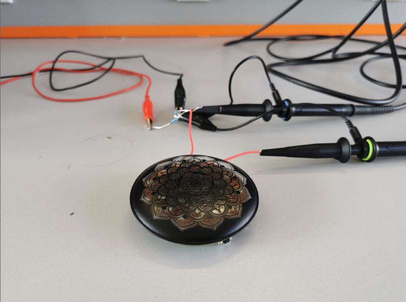
Sensing with/without plexiglass lens
Without plexiglass
Sensing without the lens works fine and can easily trigger some action…
For better visualisation, I switch on some LEDs depending of touch area.
With plexiglass
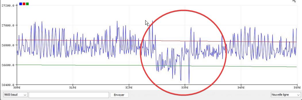
It will be far more delicate with this additional layer on the sensor. It is problably due to electrode size that have too little copper area.
To obtain something usable, I will have to forget my matrix sensor, and make only a 1 emitor / 1 receiver configuration.
The signal is weak and very noisy. I try to improve it by averaging the signal using the code bellow, where epsilon is a coefficient beetween 0 to 1 defining the update rate.
For example, epsilon = 1 mean that the average value is only the current value, epsilon = 0.5 mean that half of the average value is due to the new value.