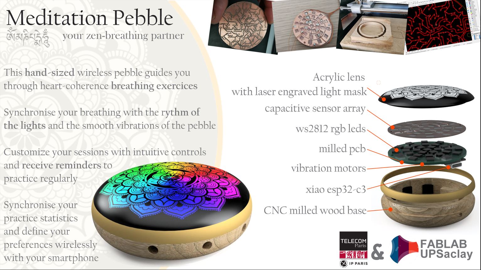
Summary Slide
Presentation Video
Files
3D modeling
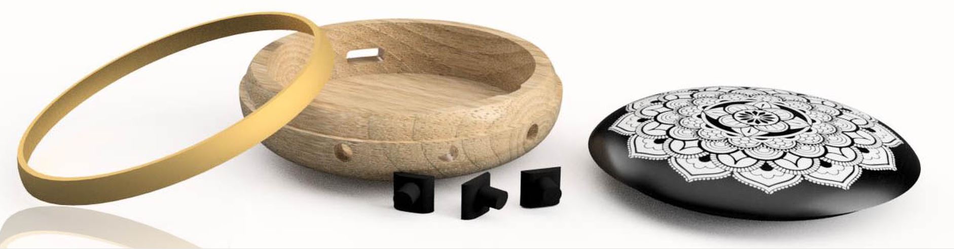
During week 2, I made the 3D model of my final project. It include wood base, brass ring, and the top glass.
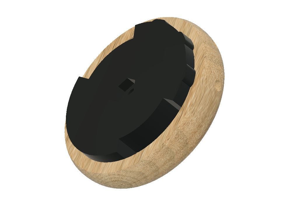
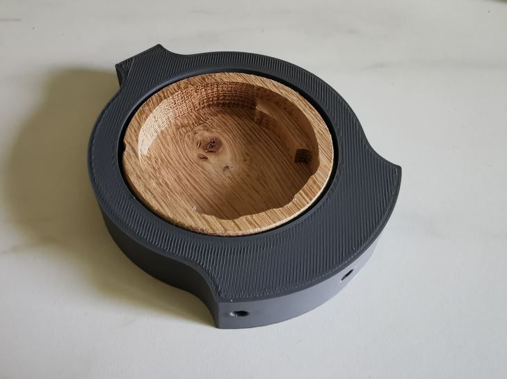
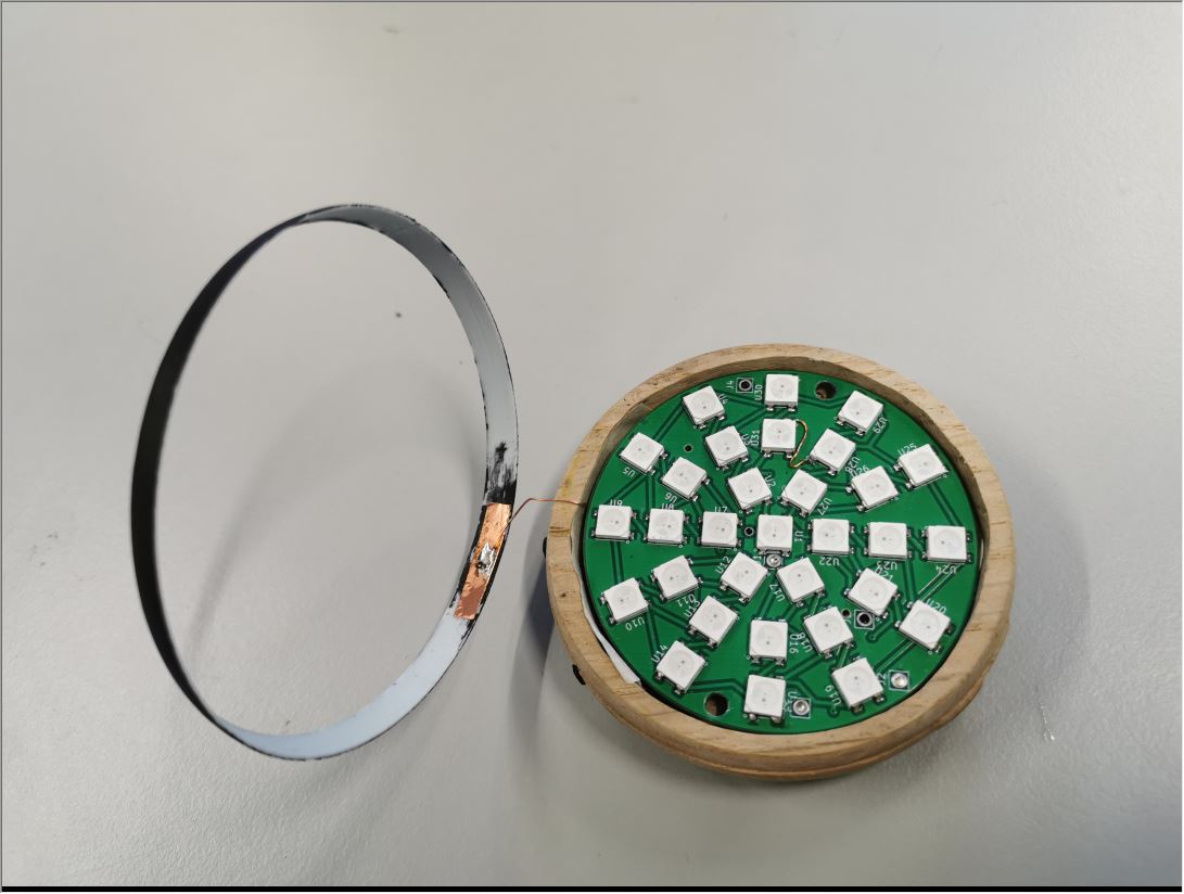
Overall view
Splitted view
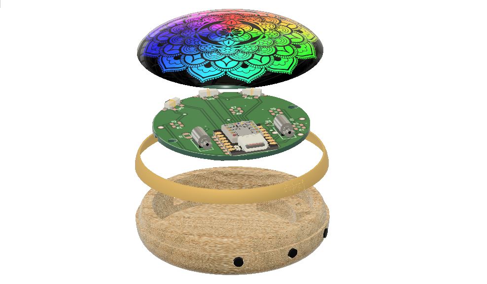 Splitted view of the different components of the meditation pebble
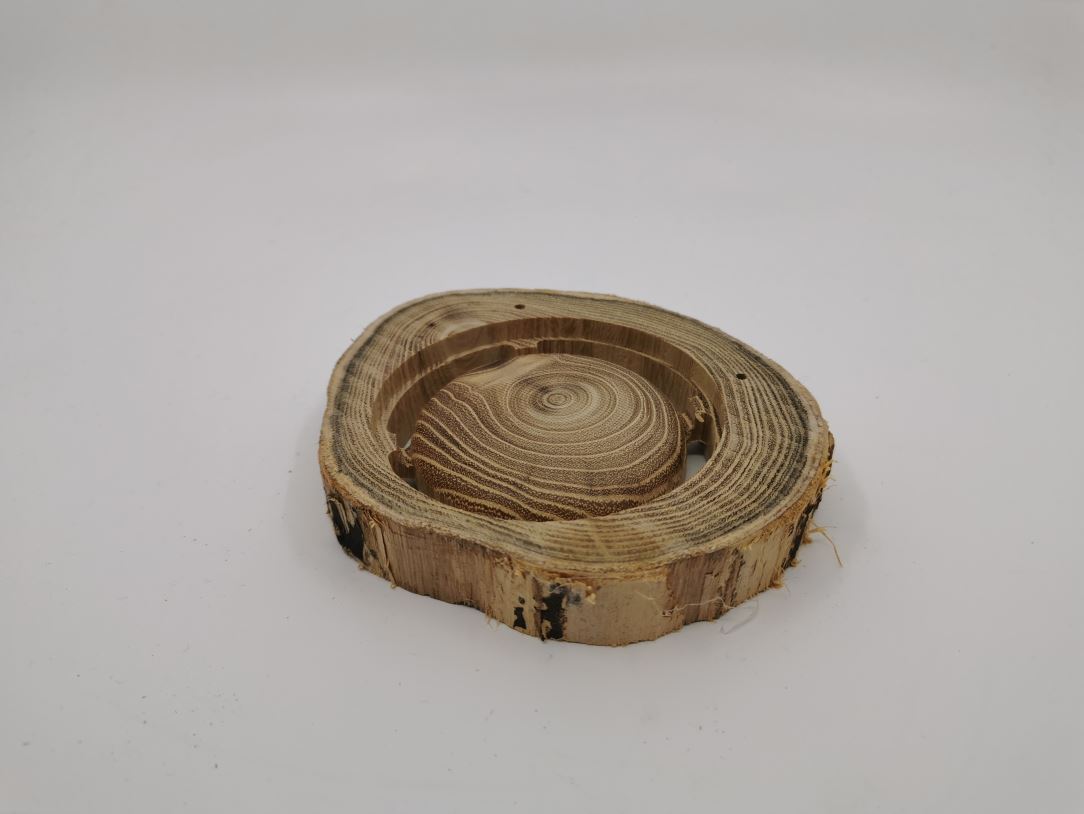
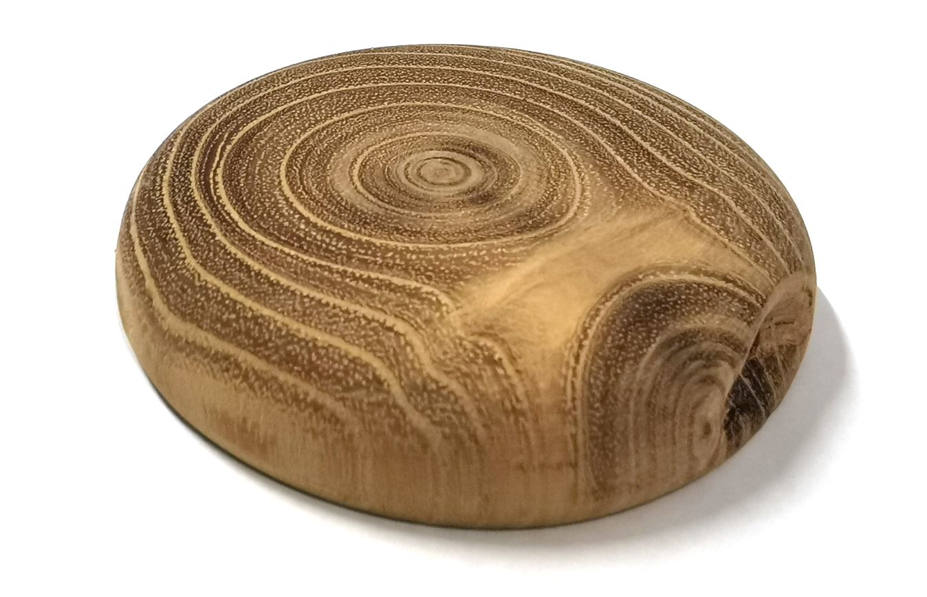
Wooden Base
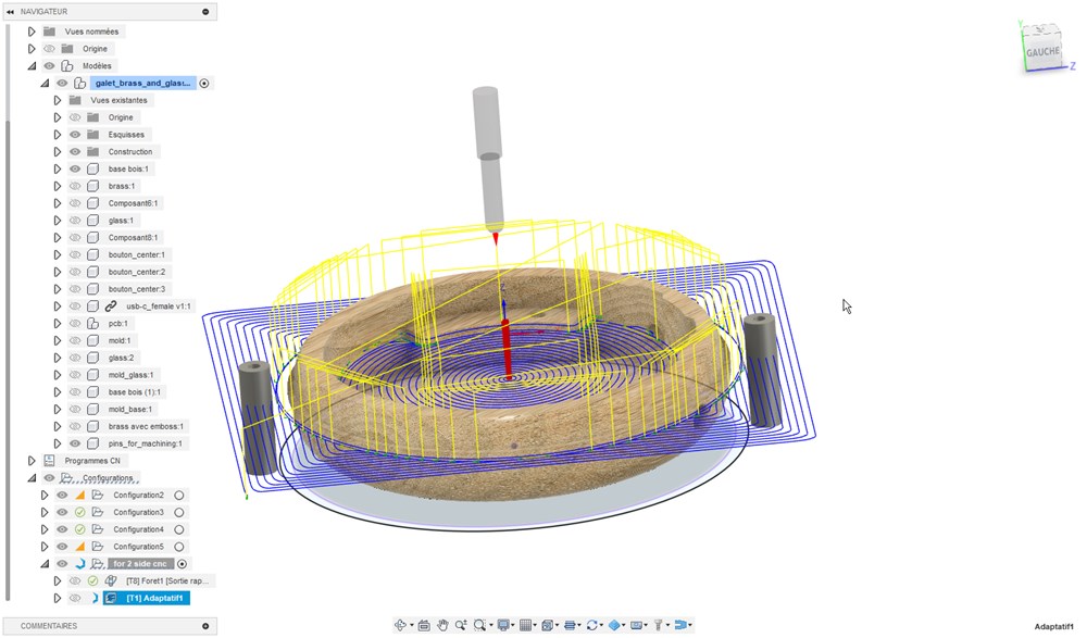
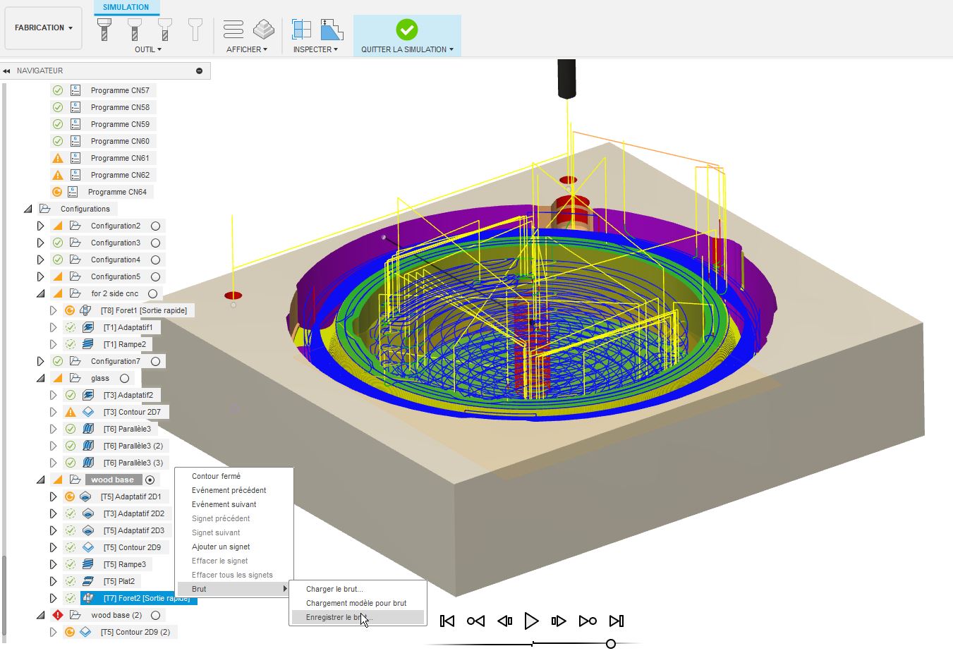
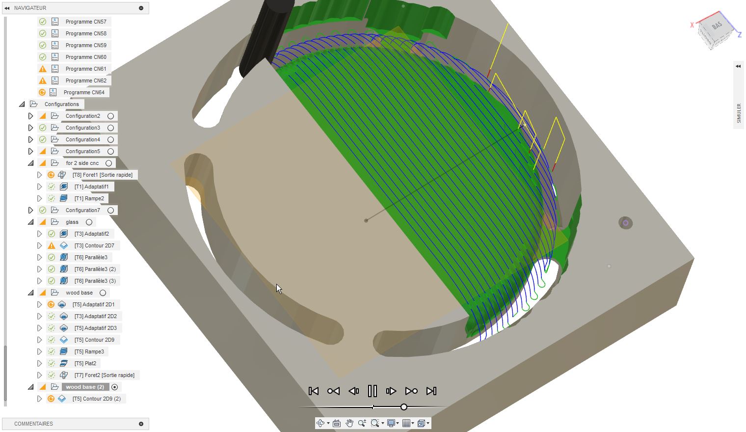
CNC machining
CAM has been prepared on Fusion360. The two sides had been prepared independently. Last step of Face A machining consist in making two 6mm holes over the stock material and 10mm inside the martyr plate. When fliping the stock material, we can realign puting 6mm rods on those holes, and we put the origin of face B on the center of one of the hole for xy and on the surface for z.
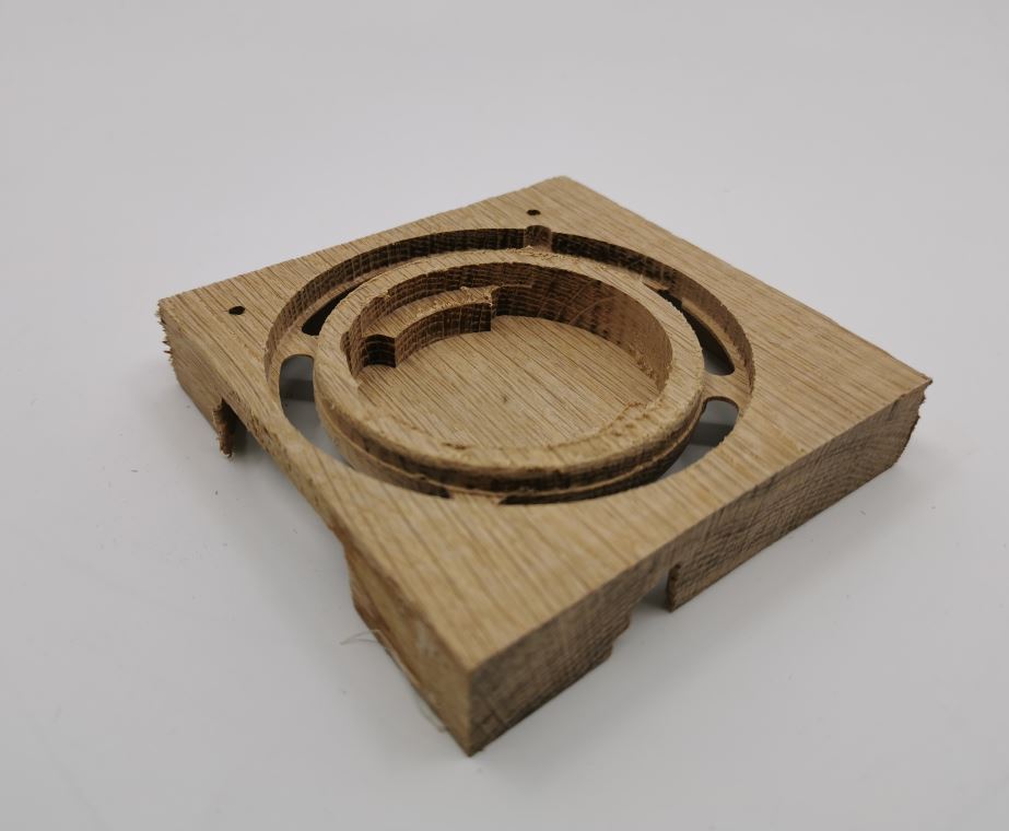
Result
Result of machining from an oak plank sourced from a local store.
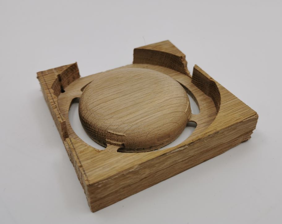
Result of machining from a log cut given by my brother living in the countryside.

Finishing
I create some tools to facilitate the differents finishing steps.
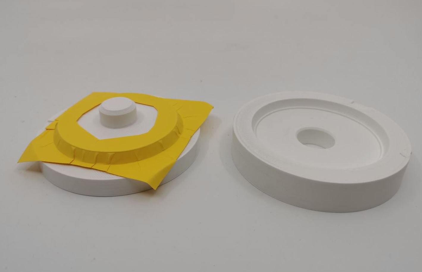
Polishing
The wood surface after machining is a little bit rought. In order to accelerate and homogeously polish the surface, I create a part to hold the pebble into a drill. I made a 0.07mm offset to that the piece should fit by friction.
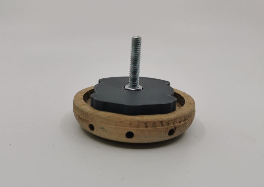
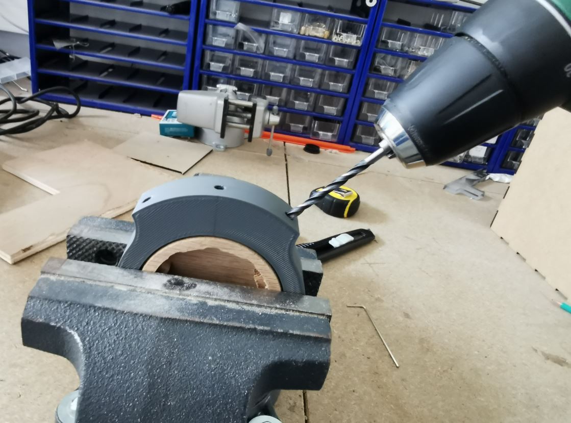
Drilling around the base
I create a guide to drill the buttons and usb holes. I designed this piece aroud the 3D model of the pebble. I extend the drilling faces to guide the drills more precisely.

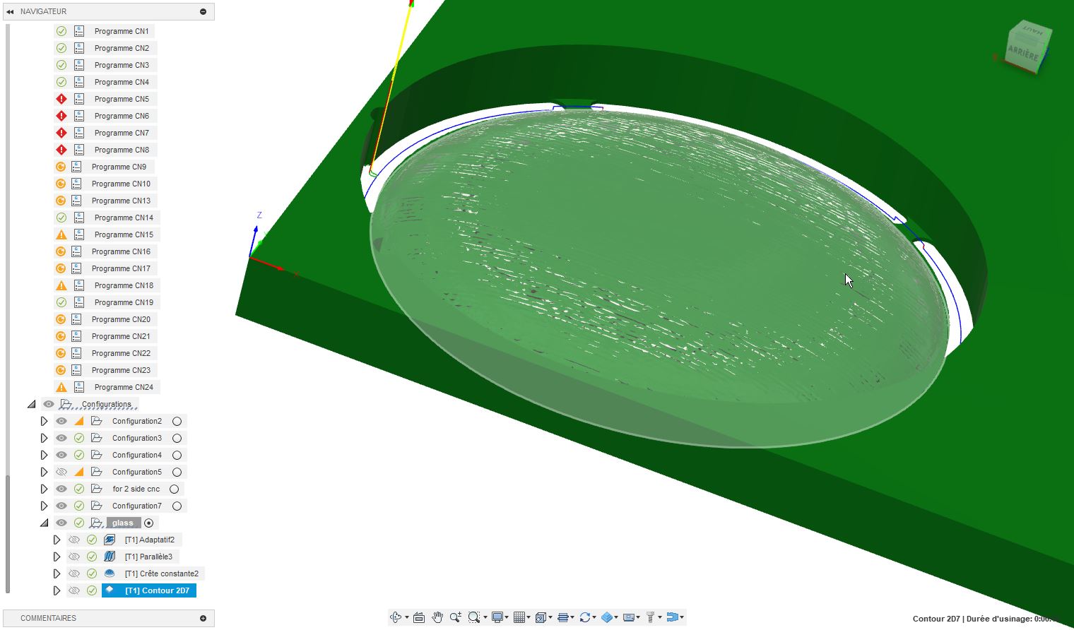
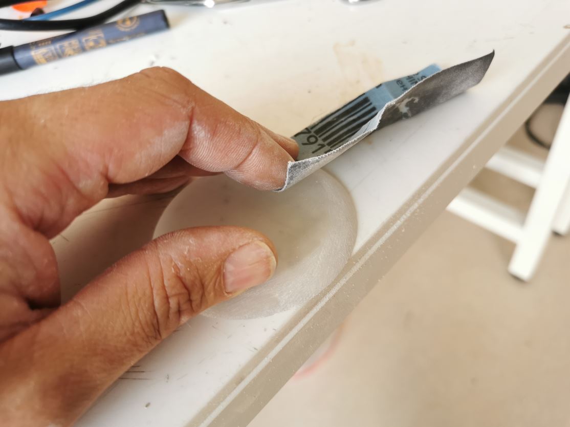
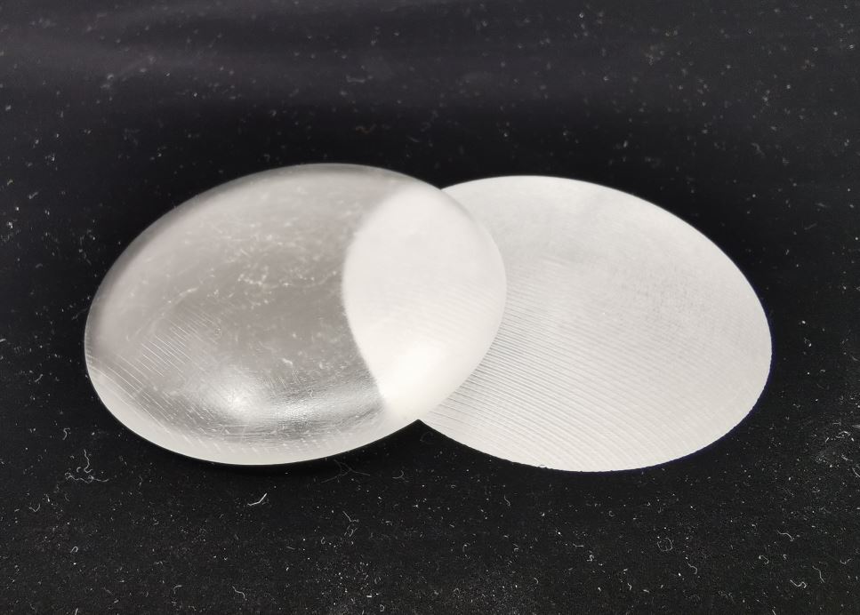
Top lens
First an adaptative 3D with a 0.5mm rest machining, then a 2D contour with the same tool. For finishing I use a ballnose 3mm and a parallel machining followed by another perpendicular (tool at 90°).
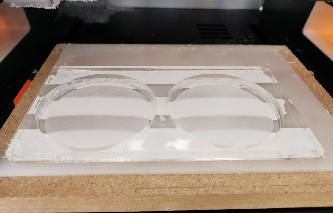
I finish the lens creation process by a manual polishing with a 800 sand paper.
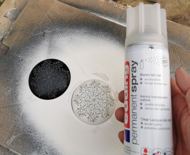
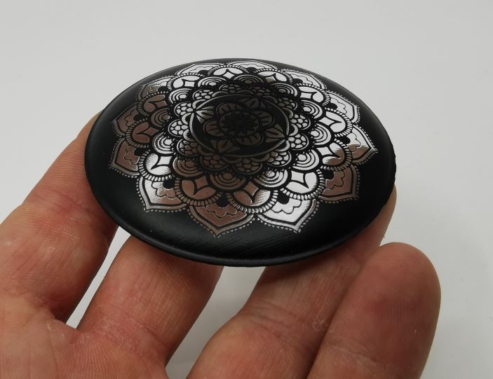
Paint layer
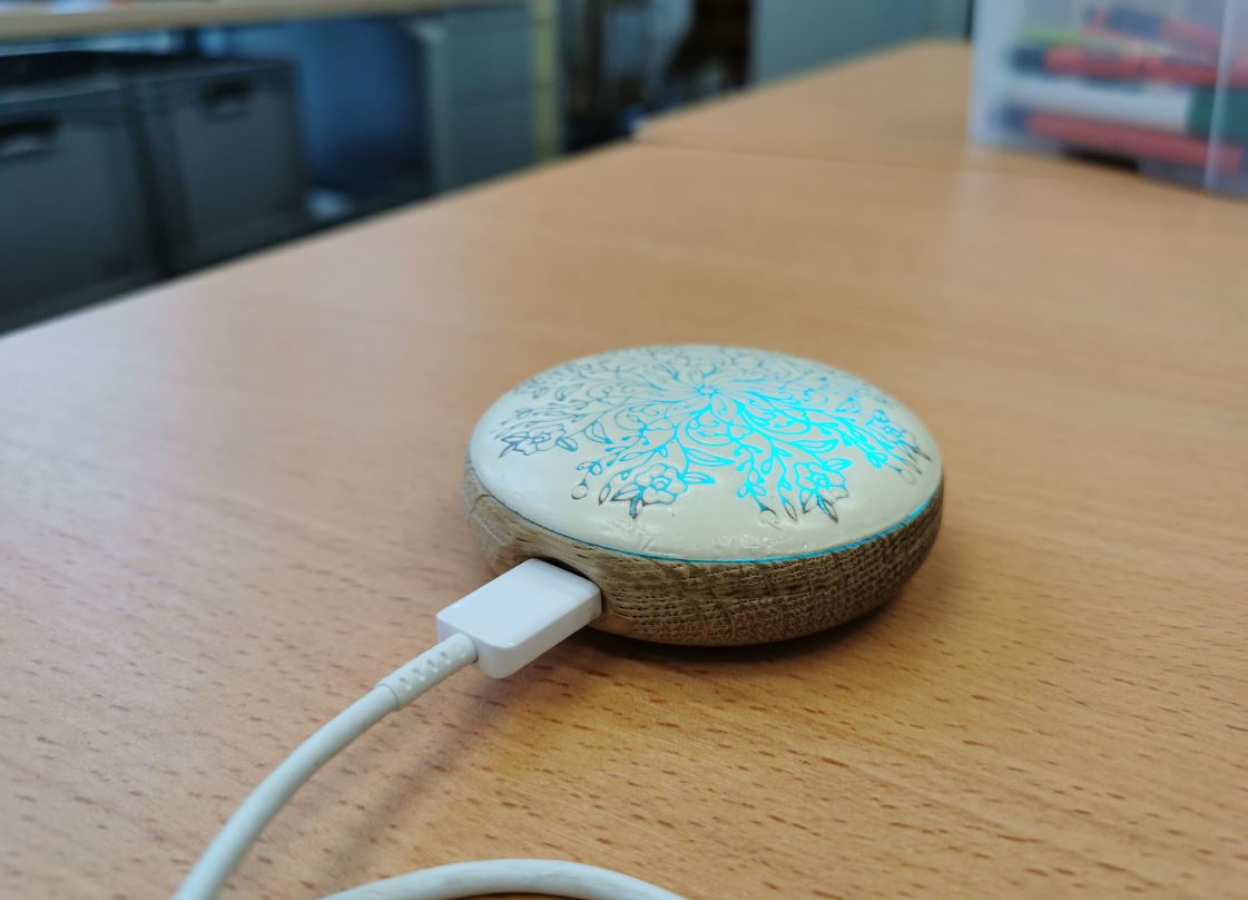
I found that 3 layer of black (or white) spray paint are good to totaly block the light. Then I spray 2 layers of clear slik mat lacquer to improve robustness and avoid scratches on the dry paint.
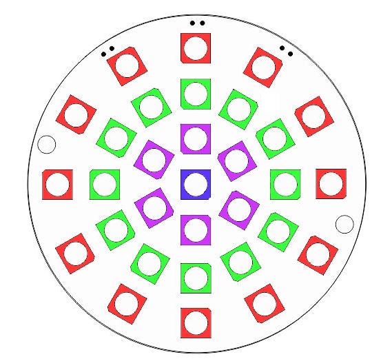
Engraving the lens
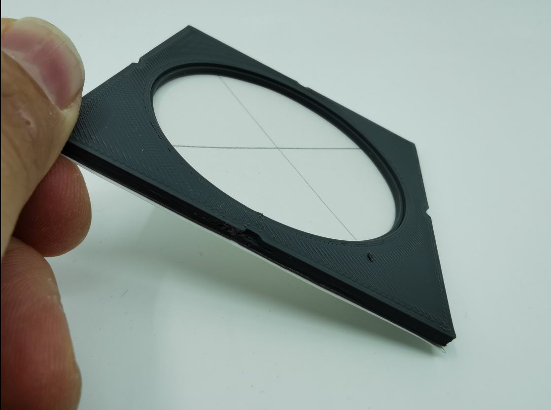
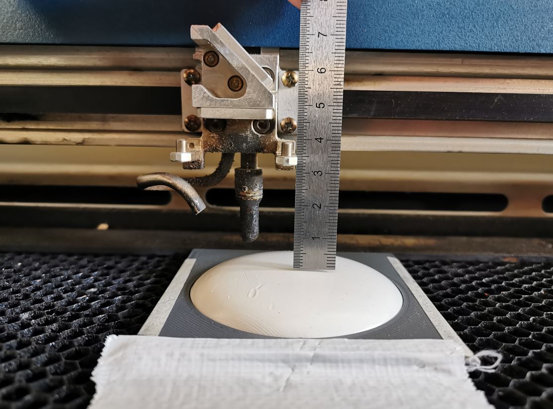
Then we remove the black paint thank’s to laser following our mandala patern with the laser cutter. To center the print on the lens, I design a 3D printed holder and make the x/y zero at the center of it. As machining and paint coating a lens is long, I made a print test on a 3mm MDF disk to ensure that alignment is correct.
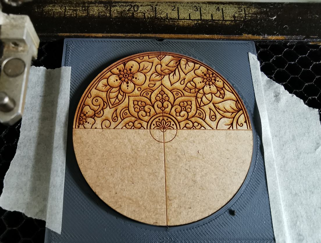
Be carefull to disable the autofocus. I check the distance beetween the laser lens and the materiel when autofocus has been made. Then, I disable autofocus and set the distance to the highest point of the acrylic lens manually to 32mm. If found that due to height variation of the lens, the laser focalisation vary too much across the patern. It has been necessary to proceed in two steps to properly engrave the center and edges of the lens:
- Engrave once at 32mm from the lens
- Then do the same engraving at 22mm
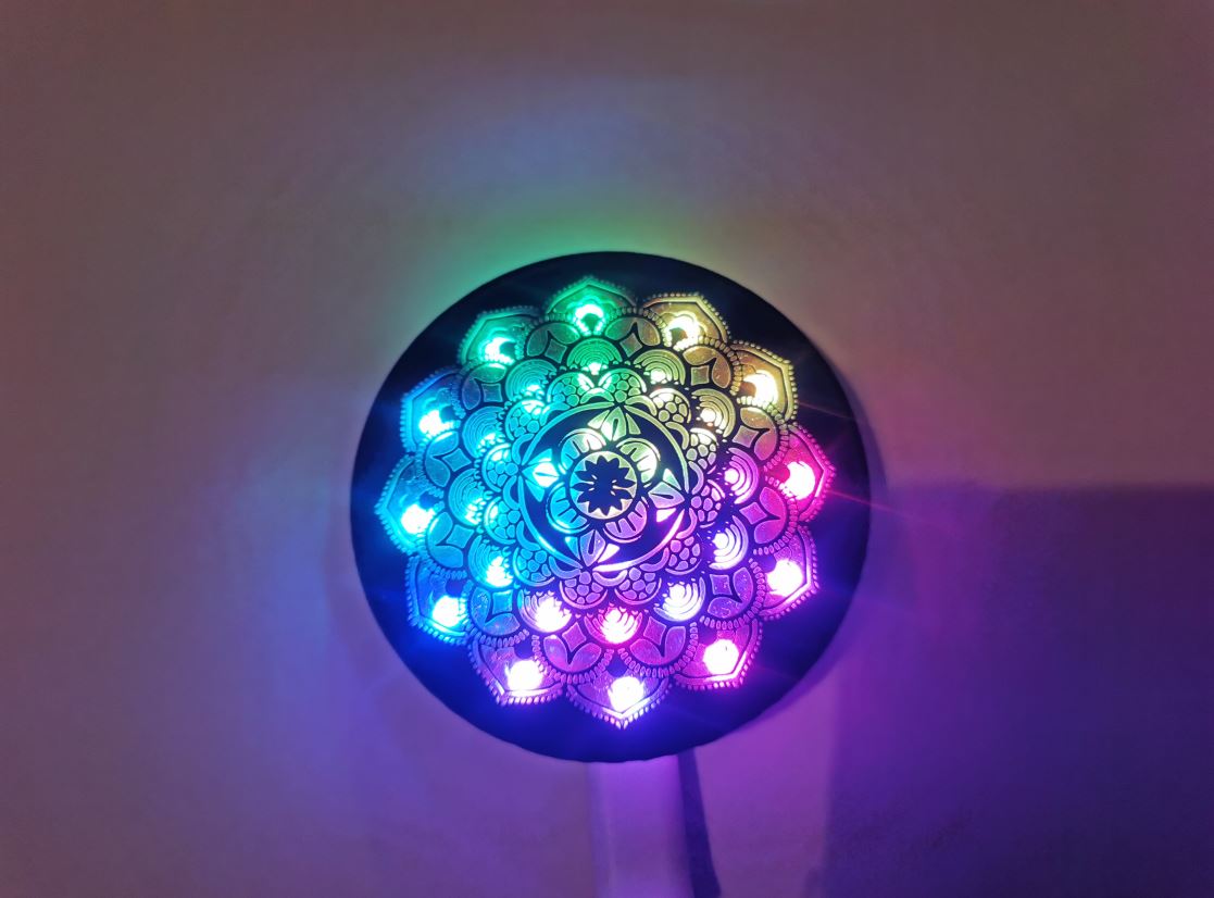
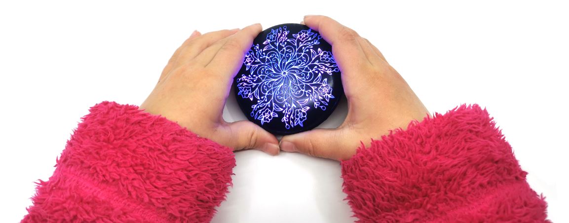
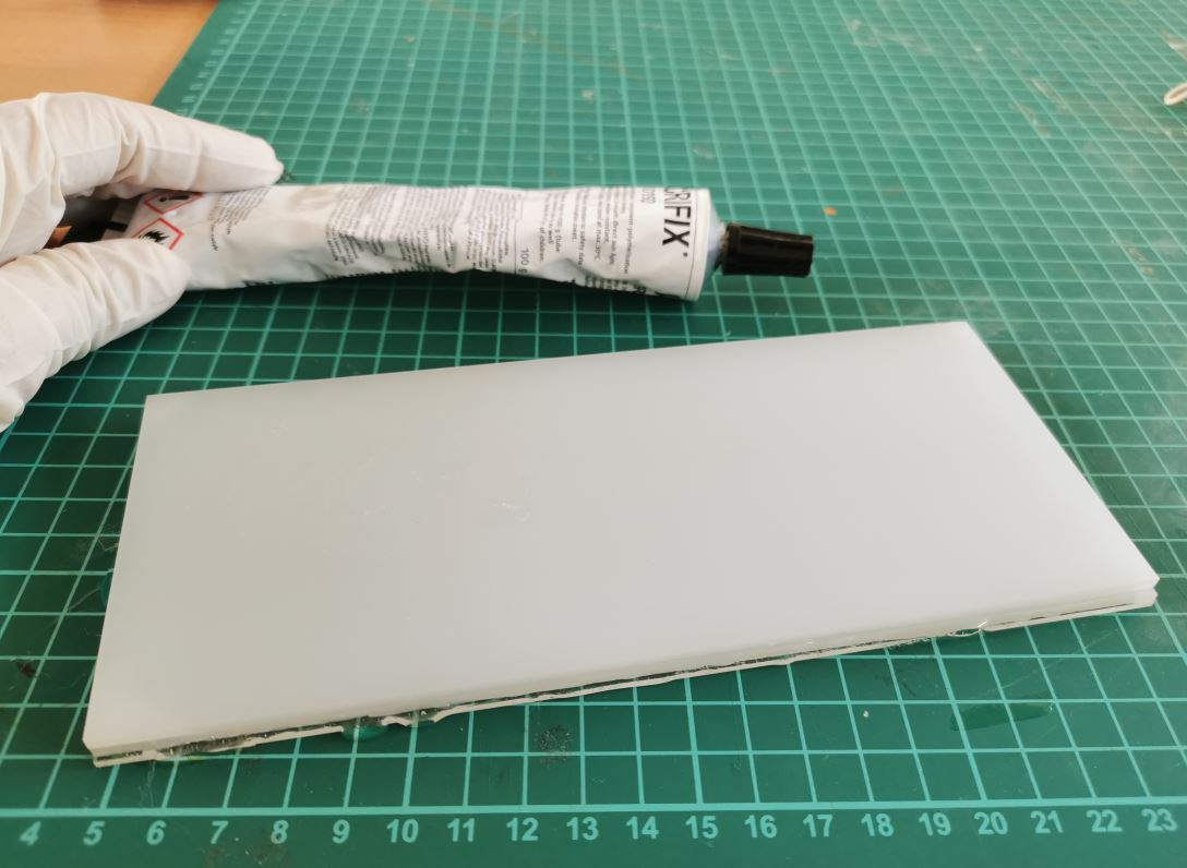
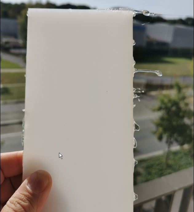
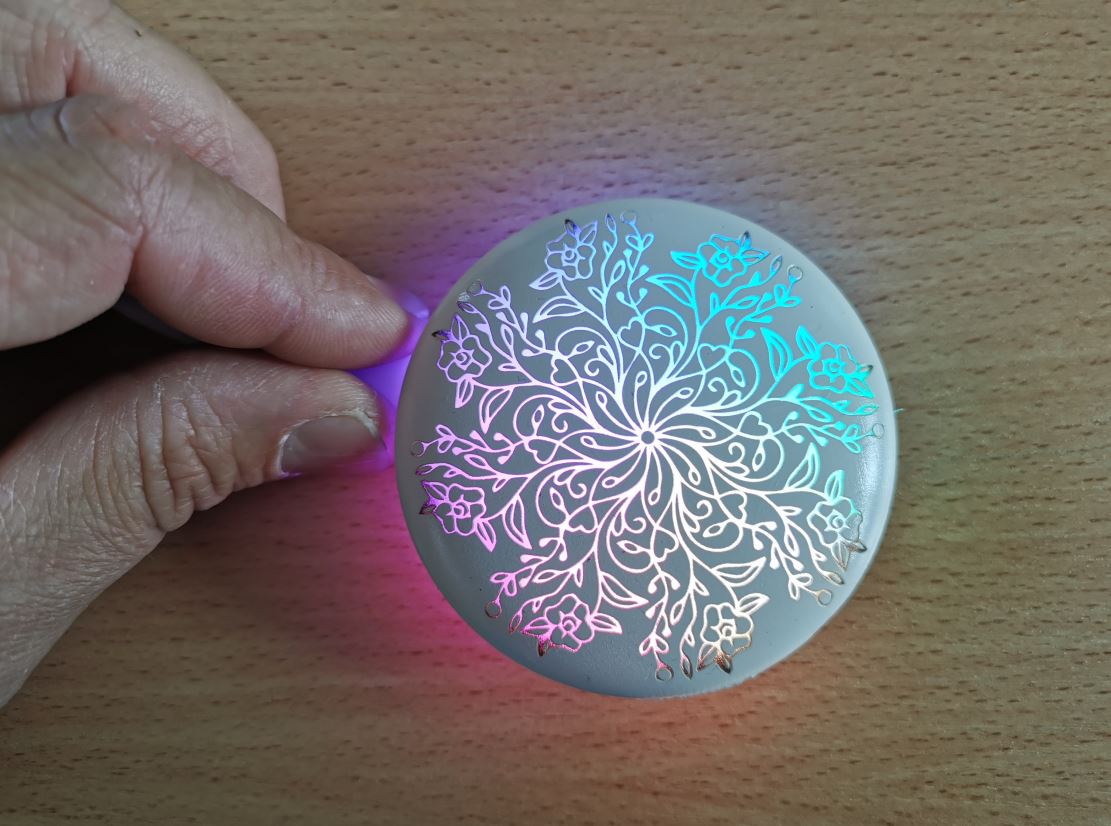
Light diffusion
Light is not homogenous on the top pattern, I try to add a diffusion sheet of paper under the lens but we can still seen the leds spots. I then used TroGlass LED Blanc mat acrylic (https://shop.troteclaser.com/s/product/troglass-led-blanc-mat-117208p/01t4I00004k6lDWQAY?language=fr). This material is specialy made to diffuse led light. Unfortunatly, it exists only a 3mm thickness where I would need 7mm. So I create a stack of 1mm clear acrylic and 2 sheet of 3mm TroGlass. I glue them with “Acryfix” acrylic glue.
Light test
It is far better!
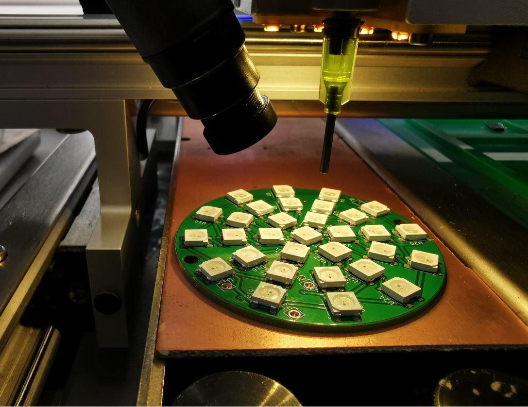
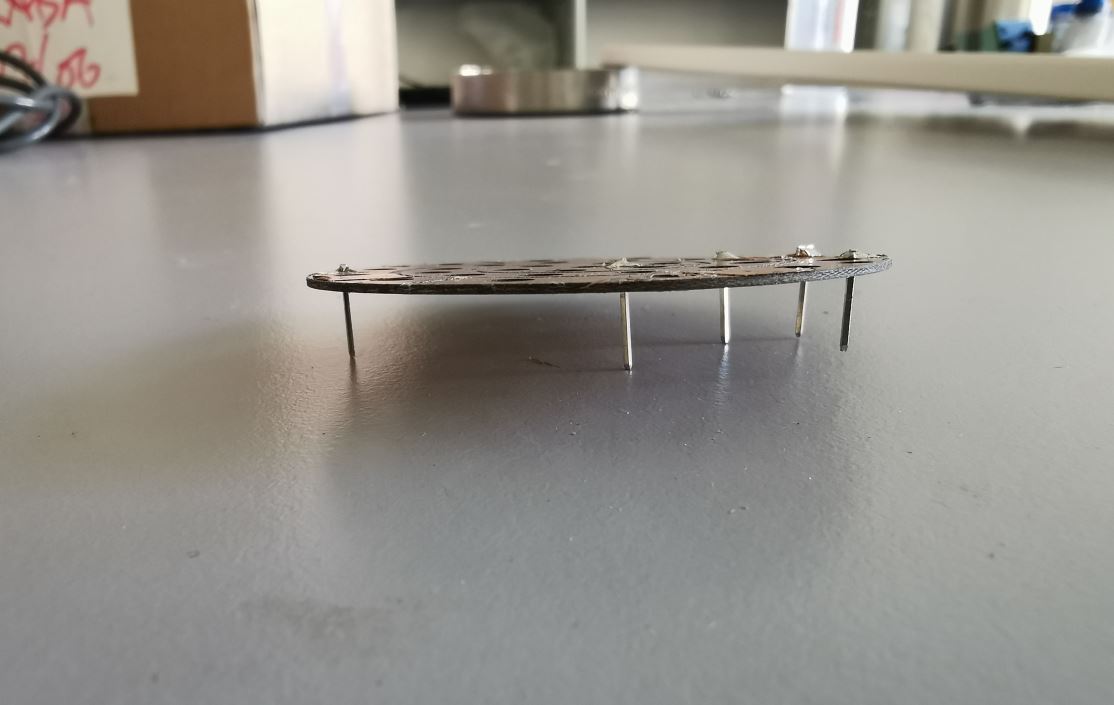
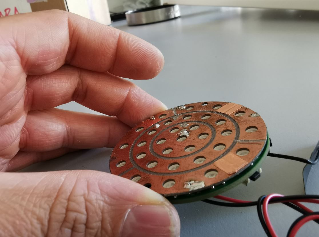
PCB
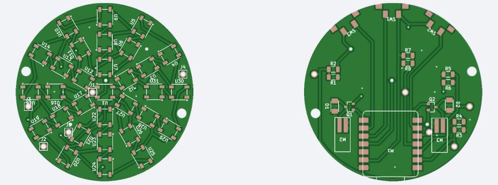
I use previously order PCBs from JLCPCB online store. I use them instead of my lab made prototype because milling double side pcb is long and I have several board to make. Furthermore silkcreen is very usefull for parts placement!
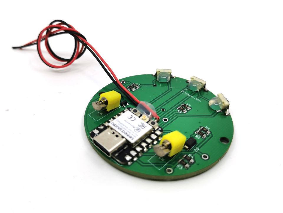
I add a 500mAh 3.7V lipo battery and fix it with a double side tape.

Programming
Remote interface
I implement a webserver on the microcontroler to serve the Graphical User Interface of the pebble. See week 13 for details about how it can be done.
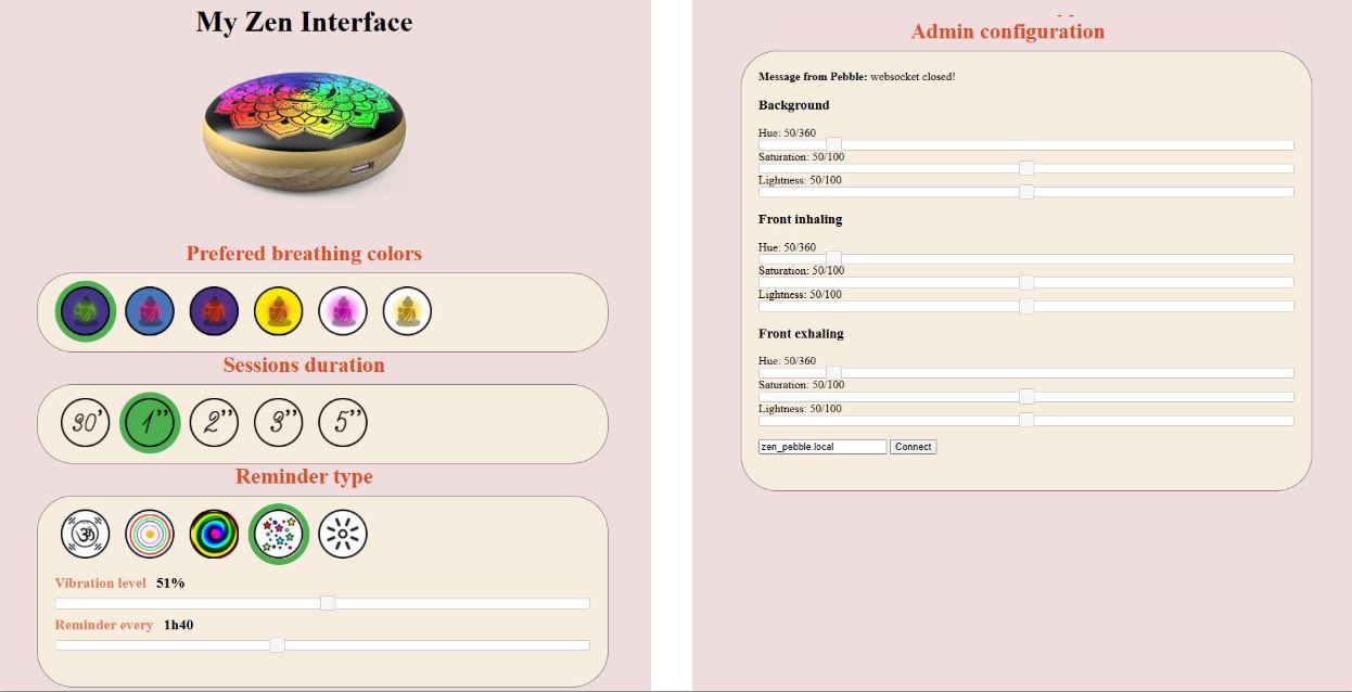
Click on buttons and changes on sliders triggers javascript methods that send parameters to pebble webserver. Here is two examples for first breathing color button and vibration level slider:
|
|
Breathing effect
I want a light growing from the middle then going back to the center. To do that I took the index of leds from center to edges and orders then in 4 zones: center(blue), ring1(purple), ring2(green), ring3(red).
For each group, I change intensity and color depending of the time (moving) and the group distance from the center (fixed).
I use a gaussian to change led intensity and led color over time. For the color, I modify the hue value of an HSL color variable to go from a background color to a foreground color (the color of the breathing wave) and use the gaussian intensity to oscilate beetween those values.
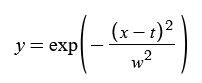
- y is the intensity of parameter
- x is distance from center. Values for groups are respecively 0, 0.33, 0.66 and 1.
- w is the width of the gaussian, it change how the groups “overlaps”. I set w empiricaly to 0.6.
I made a video explaining how intensity at each group change over time. I use this online tools to visualize equations dynamicaly: https://www.desmos.com/calculator/
The orange points represents values in each goups. Note that the gaussian center doesn’t start at 0 and doesn’t stop at 1. I add a 1.2 time offset at the begining and the end to allow first last and group to reach minimal intensity of the gaussian.
On arduino we have those keys parameters, variable used as time is progress:
|
|
There is still a lot of code as the one to make transition between 2 colors (background color and “breathing wave” color). You can check the .ino file of the project for more details.
Sensor Layer
In order to make this device a little bit more “sensitive”, I wanted to add a touch sensor on top of it. My first attenpt was to make a capacitive sensor array on top of the LEDs to recognize some gesture as:
- Touch on the center
- Touch on the edges
- Clockwise/anticlockwise touch
Unfortunatly, signal was too weak when the acrylic cover was placed on top of this sensing layer (see week 11 for details). I worked around the issue with a single touch sensor connected to the pebble ring.
First attempt: sensor array (Fail!)

I solder some pins header and solder this layer to the main PCB.
Result without the cover
In this test I switch on leds depending of sensor state over it.
Result with the cover
I tried to average signal and adjust theshold dynamicaly, unfortunatly the signal is far too noisy to be used efficiently as a touch sensor. It is probably due to the 3.3V voltage used that is too low to generate a strong enough electric field beetween electrodes (?).
Touch sensor workaround on the ring
I print the ring on an FDM 3D with PLA. Then I paint it with conductive paint. I use copper tape to make the interface with a wire going to the microcontroler. This wire is connected to a QM301 touch sensor chip.
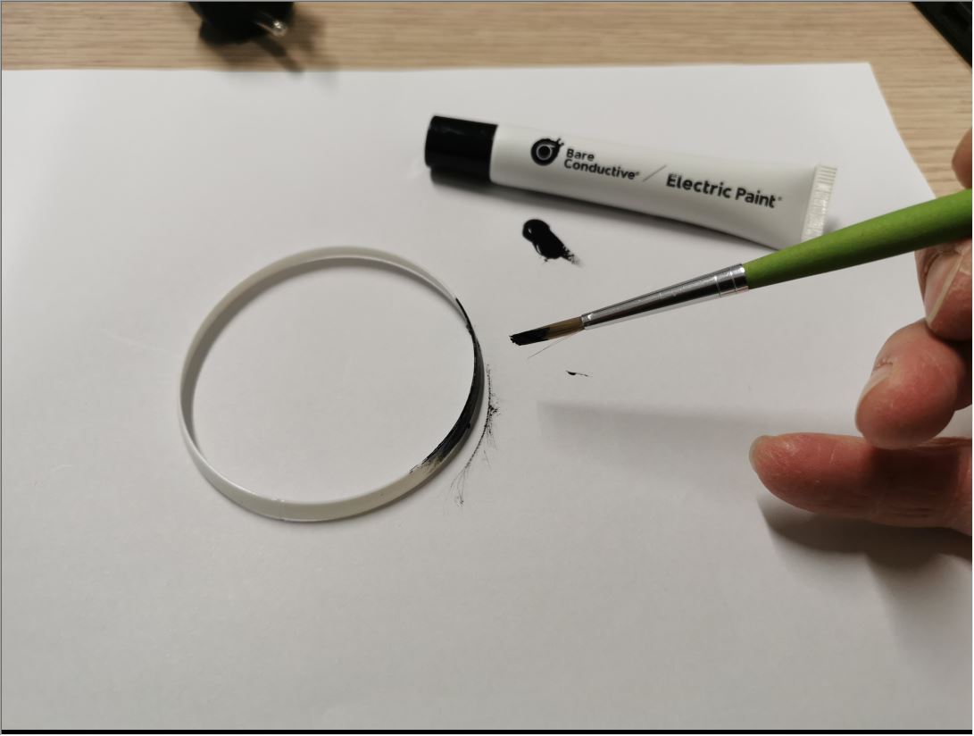
Now it is far more reliable!
Engraved ring
At the begining, I wanted a brass engraved ring around the pebble. Unfortunatly i lack the skills of a jeweler to do what I had in mind… Time was running out, and I finally opted for a 3D-printed version of the ring.
Engraving and cutting brass
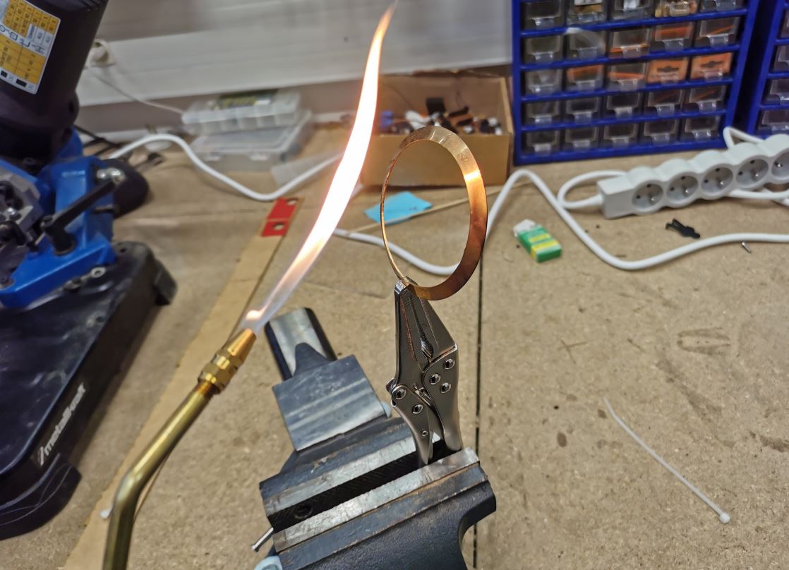
I use 1mm thick brass sheet. I reduced ring thickness to 0.5mm before engraving and cutting outlines.
Press die
To give the appropiate ring shape from a flat piece, I 3d-printed a male and female press-die in PLA with 100% infill in order to improve robustness.
To help modeling the ring, I first heat the brass with a torch to anneal the metal, making it easer to make it softer. Unfortunatly my home-made press die doesn’t work fine enough. I only managed to achieve a conical shape and not the desired rounded shape. For now I just approch the target shape with an hammer but it is not very convincing…
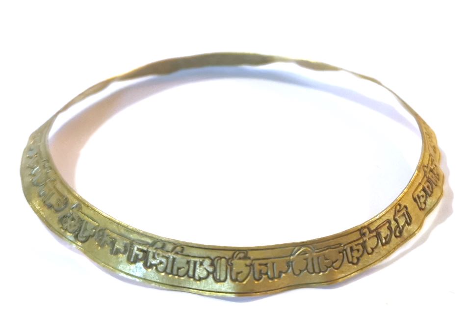
Result
UI Buttons
I made the pebble buttons with SLA 3D printing on our Form2 printer. Those buttons will push on the pcb switches when it will be in place.
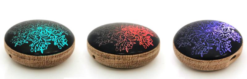
Buttons can be configured in several ways, for now the mapping is:
| short press | long press | |
|---|---|---|
| left button | switch reminder type | enable/disable vibration |
| center button | launch/stop session | switch off/on |
| right button | switch beetween color presets | restart esp |