MECHANICAL AND MACHINE DESIGN
After Neil's recitation on Wednesday 2th and 9th May, the assignment for this 2 weeks was to:
		W15 GROUP ASSIGNMENT:
			- design a machine that includes mechanism+actuation+automation
			- build the mechanical parts and operate it manually
			- document the group project and your individual contribution
		W16 GROUP ASSIGNMENT:
			- actuate and automate your machine
			- document the group project and your individual contribution
We decided to do it in an inverse process; In engineering we are used to think about product specifications before designing it. So, we are going to make in this order:

We are going to follow next steps:
		1_ Undestand electronics and connections > Connect everything > Test and Program it
		2_ Understand each components and needs > Design structure
		3_ Make it and Mount it with every electronic/mechanical components
		4_ Test it
		5_ Future Actions
Javi has been the resopnsible for electronic/programming part and Leire for the mechanical/fabrication part.
1_ Undestand electronics and connections > Connect everything > Test and program it
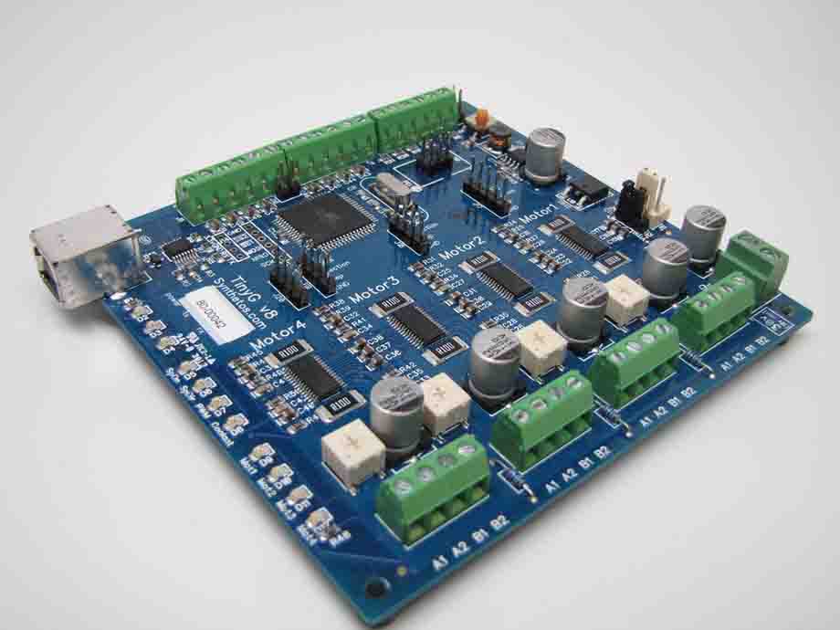
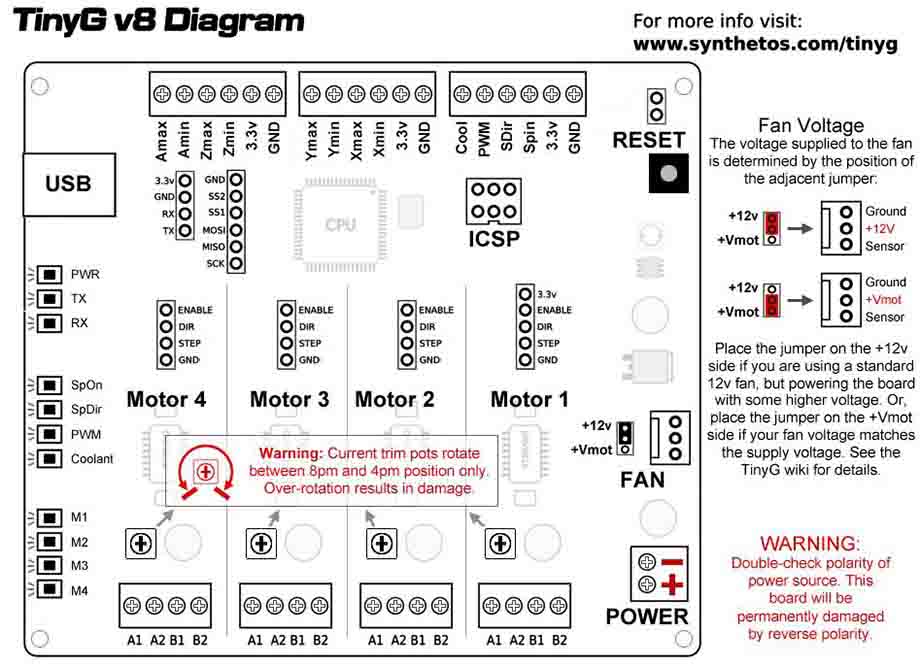
For the control of the machine we have decided to use the tinyG board. The TinyG project is a multi-axis motion control system. It is designed for CNC applications and other applications that require highly precise motion control. This board can control 4 stepper motor up to 2.5 amps per winding. We can see its connections diagram in image below:
Next we see some notes taken from its DataSheet:
Driver: http://www.ftdichip.com/Drivers/VCP.htm
CoolTerm: http://freeware.the-meiers.org/CoolTermWin.zip
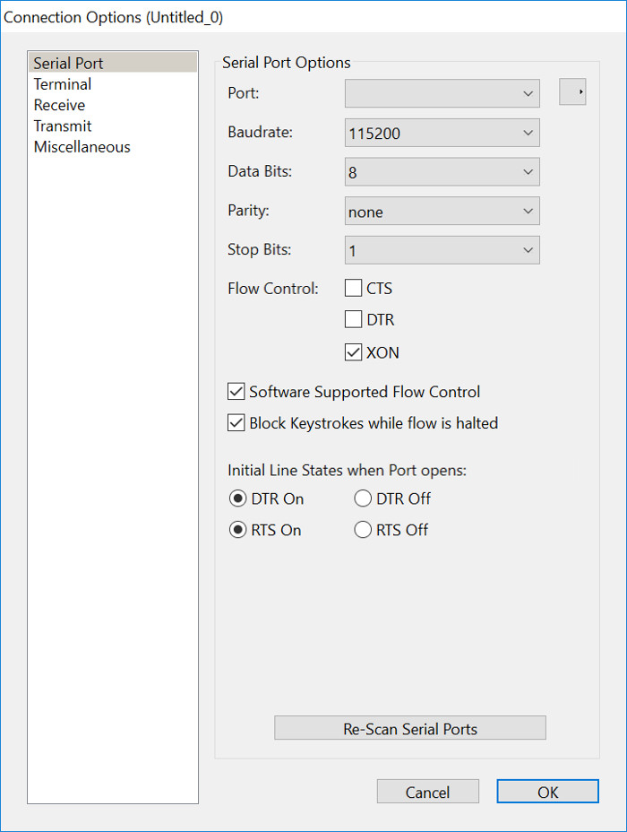
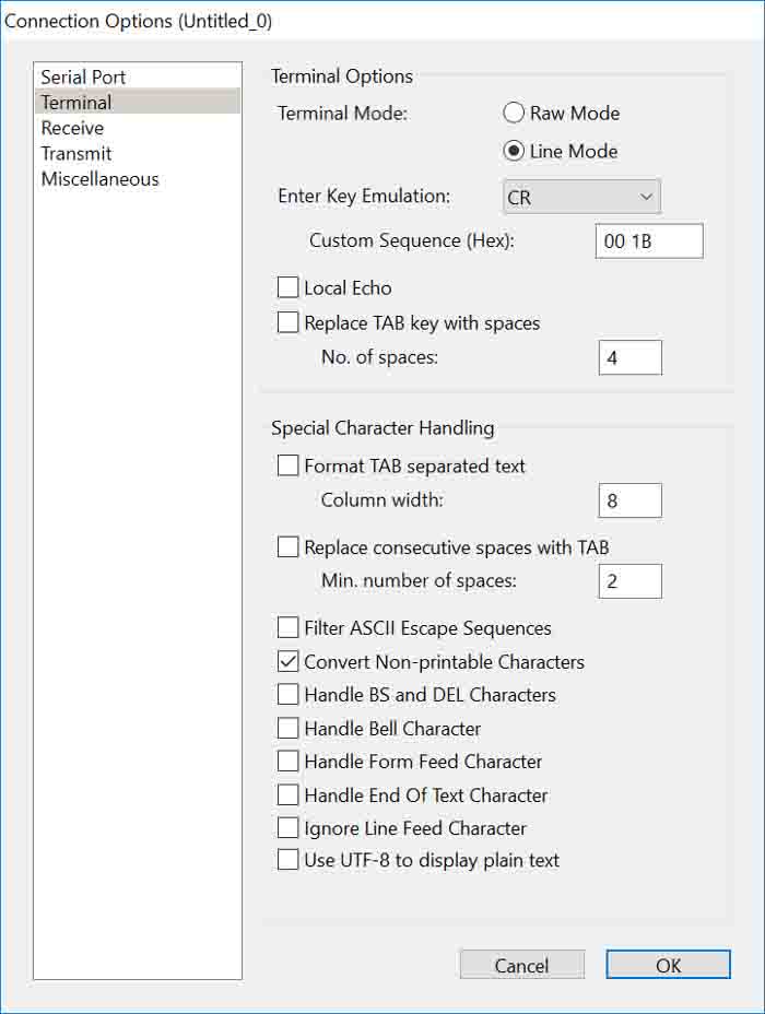
		•	115,200 baud
		•	8 data bits
		•	no parity
		•	1 stop bit
		•	XON flow control (or use CTS, but make sure the $ex setting agrees)
		•	It's also useful to set the following - but not strictly necessary
		•	Options/Terminal - Line Mode
		•	Options/Enter Key Emulation - CR
		•	Hit OK to leave the Options menu
Verify Flow Control Once you are connected it's a good idea to verify you have the correct flow control settings.
	•	The default flow control for TinyG is CTS, which uses the following settings:
	•	Coolterm: CTS checked
	•	TinyG $ex=2
	•	XON/XOFF flow control is also available. Both Coolterm and TinyG must be configured the with these settings:
	•	Coolterm: XON checked
	•	TinyG: $ex=1
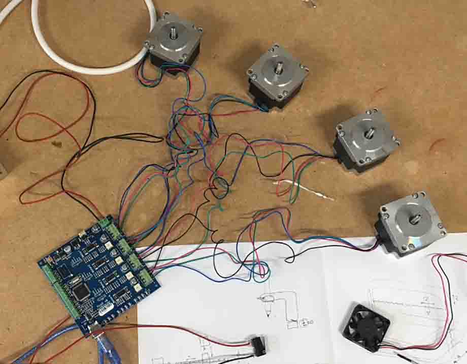
CONNECT MOTORS
We have used Nema 23 Bipolar 0.9deg motors to control 3 axis: X, Y and Z. This motors are High-torque stepper motor, ideal for applications in which a higher resolution is to be achieved in open-loop mode without encoder.
SPECIFICATIONS: Nema 23 Bipolar 0.9deg 1.26Nm (178.4oz.in) 2.8A 2.5V 57x57x56mm 4 Wires
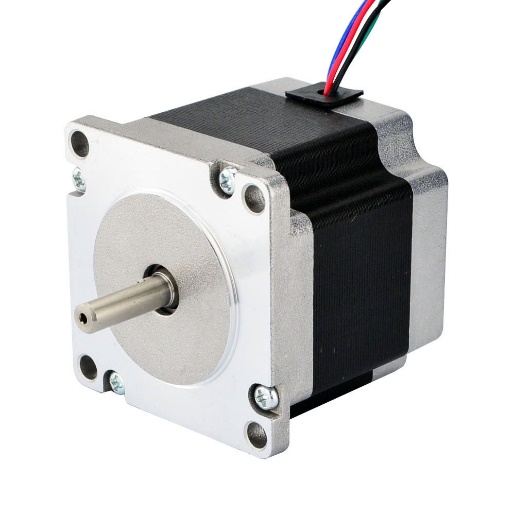
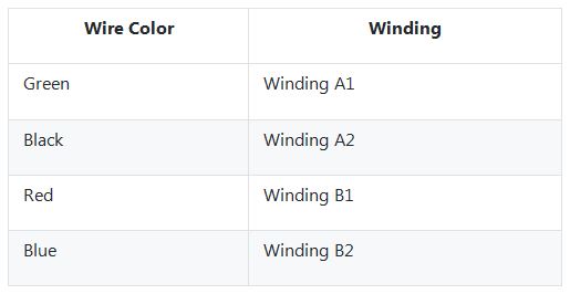
Bipolar motors have 4 wires (2 pairs). This wire color code is typical for many bipolar motors:
The next step was to wire the limit switches. The tinyG have in each input a pull up resistor, so we only have to wire the common pin of the switch to ground and the NC NO to the board.
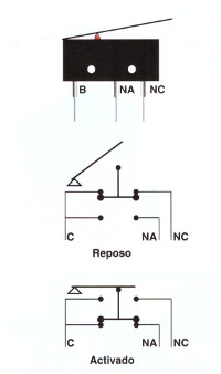
We decided to use the Normal Close option. So the NC pins of the switches to the board. We only use 3 switches:
- X min
- Y min
- Z max
Once the board was wired we began with the configuration of the board. For that we first used the coolTerm to introduce configuration commands.
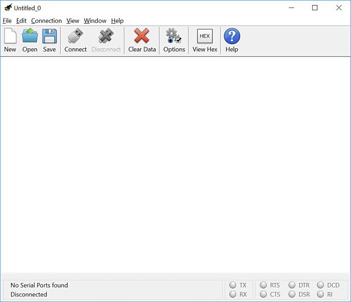
The configuration of the coolterm was:
- 115,200 baud
- 8 data bits
- no parity
- 1 stop bit
- XON flow control
And in the terminal configuration Line Mode and Enter Key Emulation - CR
In this moment we switched on the tinyG and using the CoolTerm we began to configure the board using this commands:
	$ex=1		-- XON/XOFF flow control

	$1sa=0.9	-- Motor1 a 400 step per revolution motor
	$1tr=60 	-- 3mm GT2 timing belt with a 20 tooth pulley
	$1mi=8		-- 8 microsteps

	$2sa=0.9	-- Motor2 a 400 step per revolution motor
	$2tr=60 	-- 3mm GT2 timing belt with a 20 tooth pulley
	$2mi=8		-- 8 microsteps

	$3sa=0.9	-- Motor3 a 400 step per revolution motor
	$3tr=1.25 	-- a 1.25mm pitch screw for the z axis
	$3mi=8		-- 8 microsteps

	$4sa=0.9	-- Motor4 a 400 step per revolution motor
	$4tr=60 	-- 3mm GT2 timing belt with a 20 tooth pulley
	$4mi=8		-- 8 microsteps

	$1ma=0		-- Motor 1 for X axis
	$2ma=1		-- Motor 2 for Y axis
	$3ma=2		-- Motor 3 for Z axis
	$4ma=1		-- Motor 4 for Y axis

	$4PO=1		-- Motor 4 inverse polarity

	$ST=1		-- ALL Switch Type Normaly Close

	$XSN=3		-- Xmin switch limit-and-homing
	$XSX=0		-- Xmax switch disabled
	$YSN=3		-- Ymin switch limit-and-homing
	$YSX=0		-- Ymax switch disabled
	$ZSN=0		-- zmin switch disabled
	$ZSX=3		-- Zmax switch limit-and-homing
	$ASN=0		-- Amin switch disabled
	$ASX=0		-- Amin switch disabled
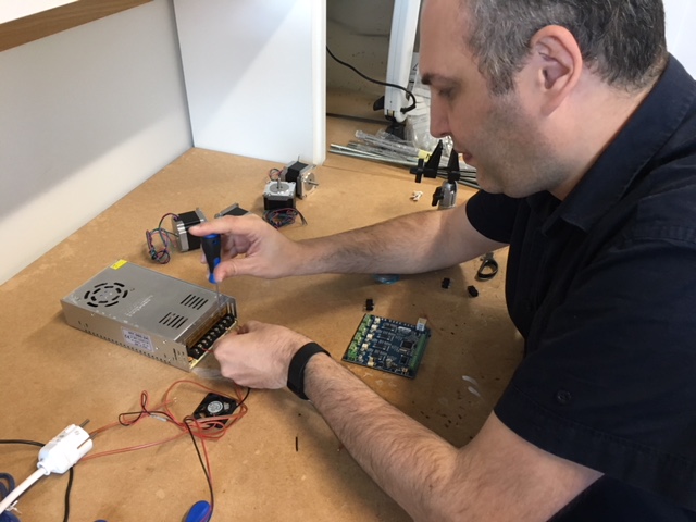
This was the first configuration. To test if all was correct the $test=1 was introduced. All the motors were working well unless the fourth motor that was getting hot. We switch off all and check the connections and the configuration. Finally the problem was the power configuration, the fourth motor was always on. We change the configuration to only power the motors in operation.
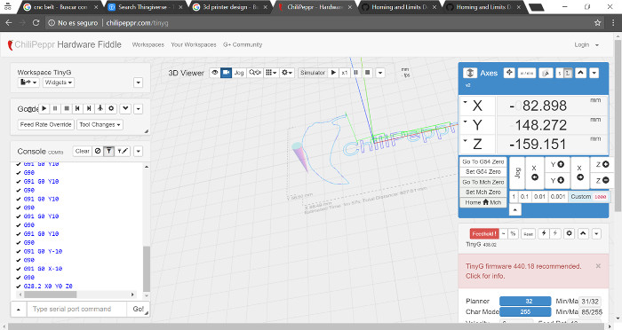
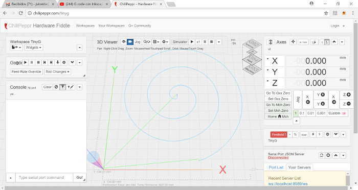
Once the basic configuration was tested we began to use chilipeppr. This a web based cnc control software that can be used with the tinyG board. We needed to install a serial port server. After run the serial port server the chilippr web is able to communicate with the tinyG board.
Using the top right panel int clilipeppr we can move the machine in each axis, pushing the arrows.
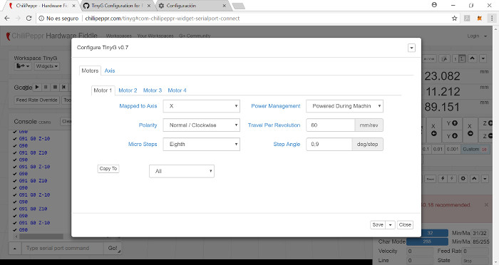
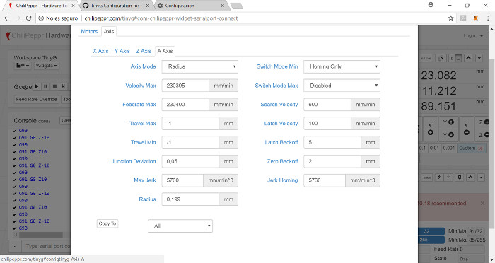
The final board configuration was done using chilippr interface, pushing the gear icon. We can configura each motor. In the next picture the configuration of the first Motor can be shown.
In the next picture can be shown configuration of the second Motor.

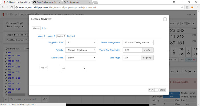
In the next picture can be shown configuration of the third Motor.
In the next picture can be shown configuration of the X axis.

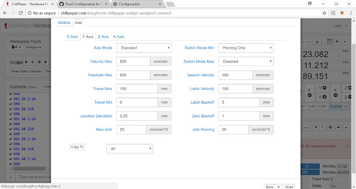
In the next picture can be shown configuration of the Y axis.
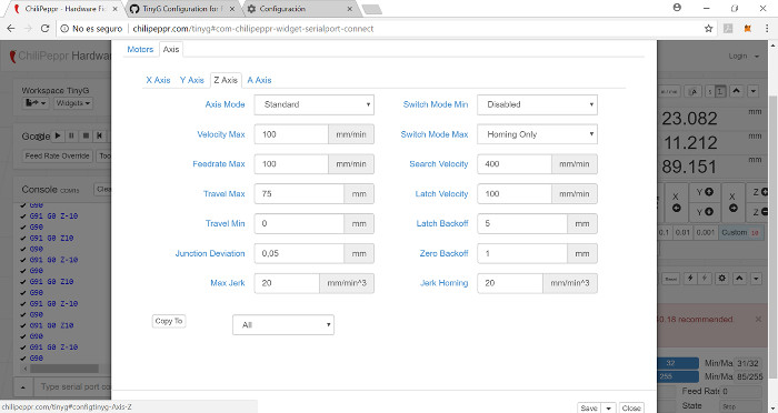
In the next picture can be shown configuration of the Z axis.
In the next picture can be shown configuration of the A axis.
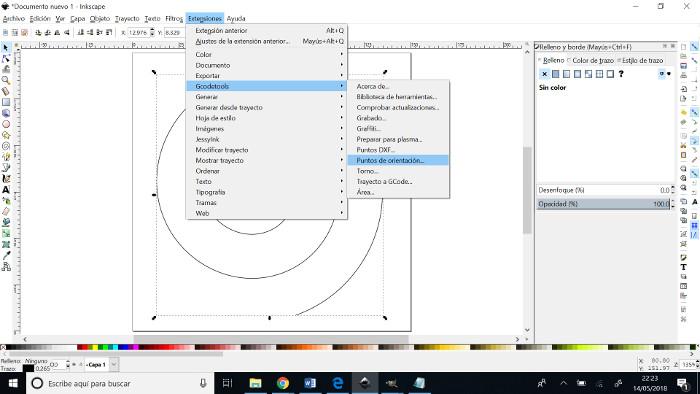
To generate the gcode for our machine we have used inkscape.
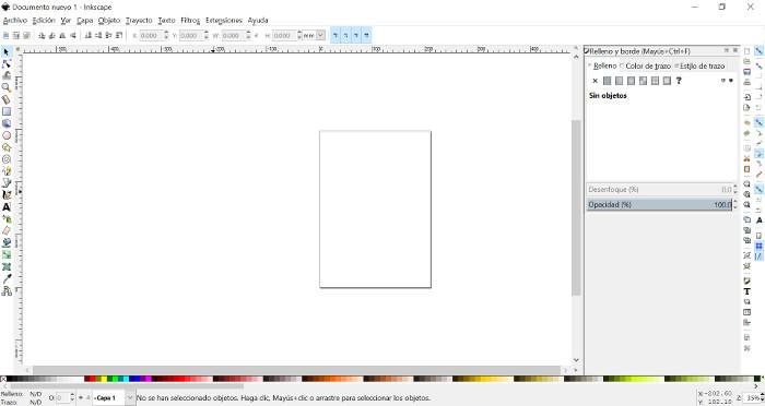
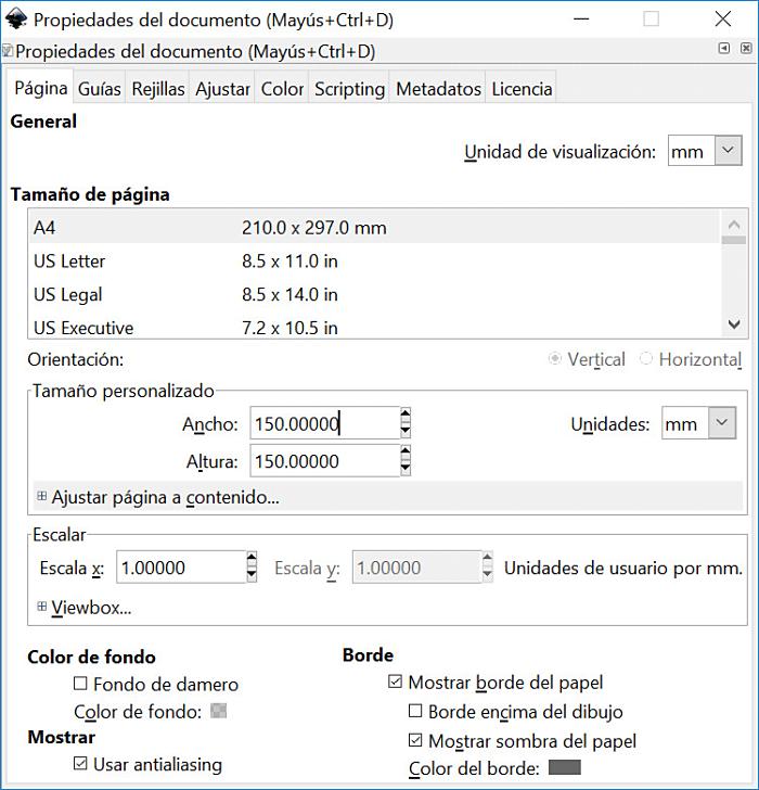
First we introduce the working area of our machine.
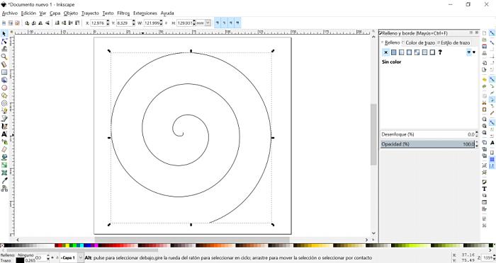
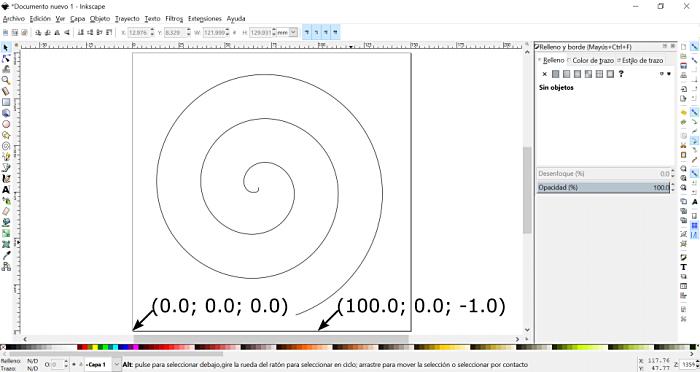
Next, we draw an spiral to test our machine.
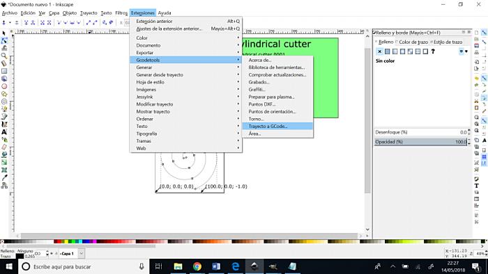
Inkscape has an extension to convert drawing to GCODE, so using it:
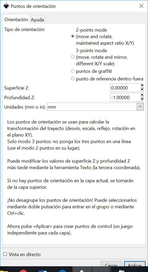
The next step was to define the orientation points for the machine.
We defined a deep of 1mm in the Z axis.
The reference points appears in the next figure.
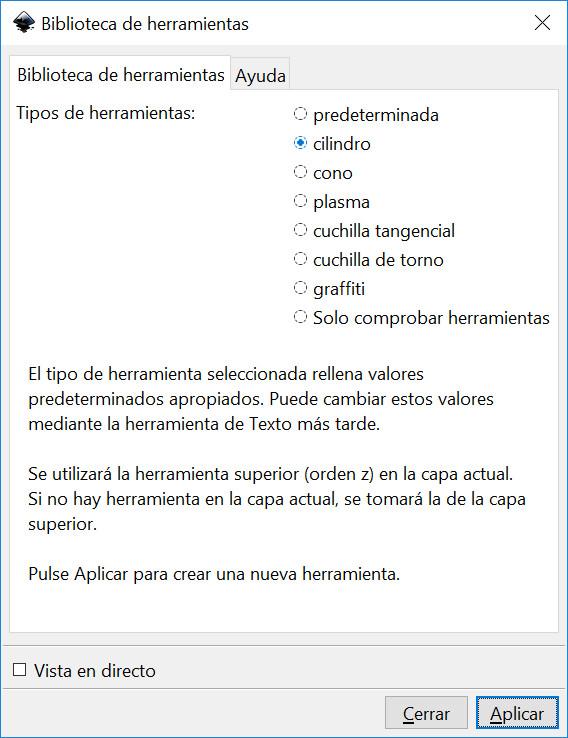
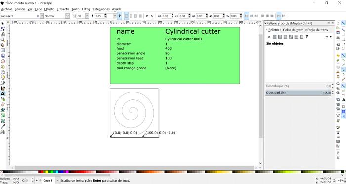
The next step is to define the tool of the machine.
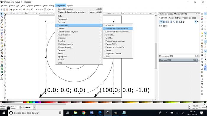
We decided to use an cylinder of 1mm of diameter.
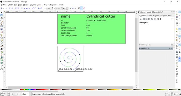
The final step is to convert the object to gcode and send it to a file.
We can see the defined path in the next figure.
Finaly we imported the generated gcode to chilippr, push play and pray.
But first of viewing resulting videos we explain mechanical design and making process below:
2_ UNDERSTAND EACH COMPONENT NEED > DESIGN STRUCTURE
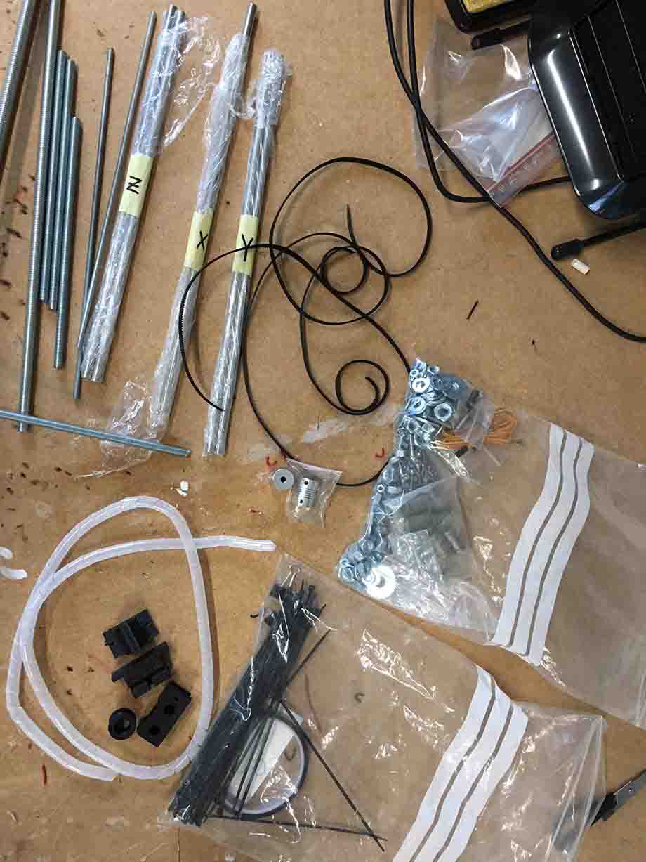
Once we had a clear vision about electronics and components (motors, switches), we began to gather mechanical parts we need for the structure and movements transmisions.
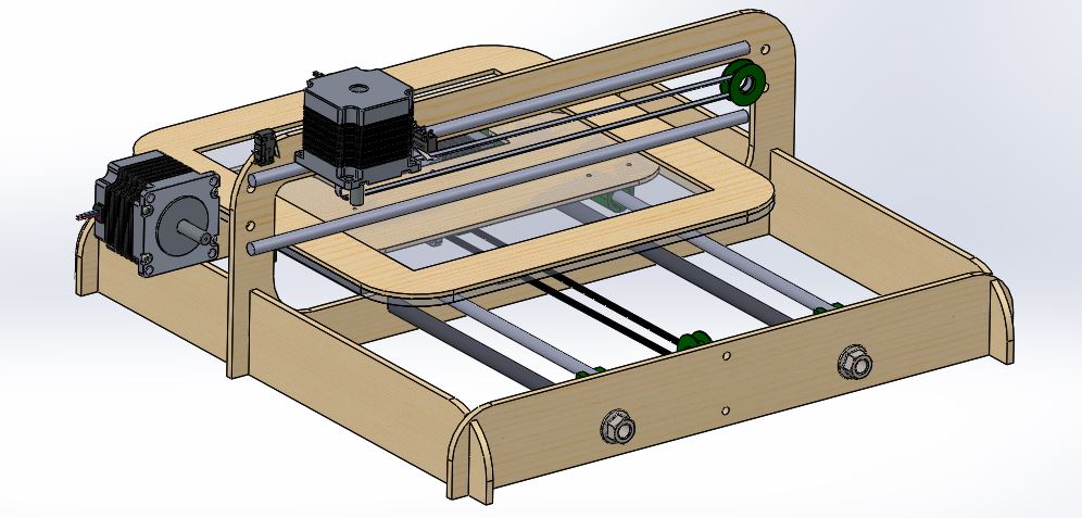
We were inspired by the Prusa since we had leftover components from an assembly kit.
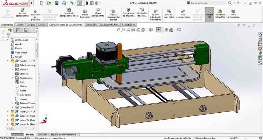
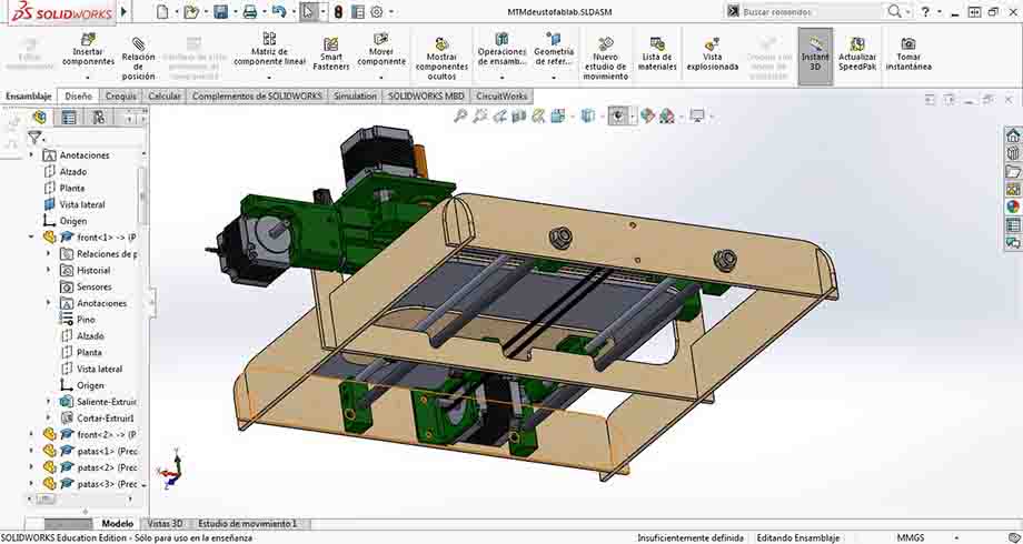
So, using SolidWorks, we began to assembly its different parts like rods, shafts, belts, screws, nuts, etc. Some of them downloaded from web repositories, some of them reproduced by us taking general dimmensions.
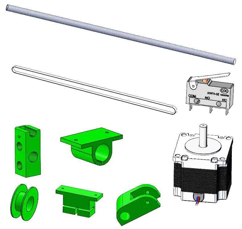
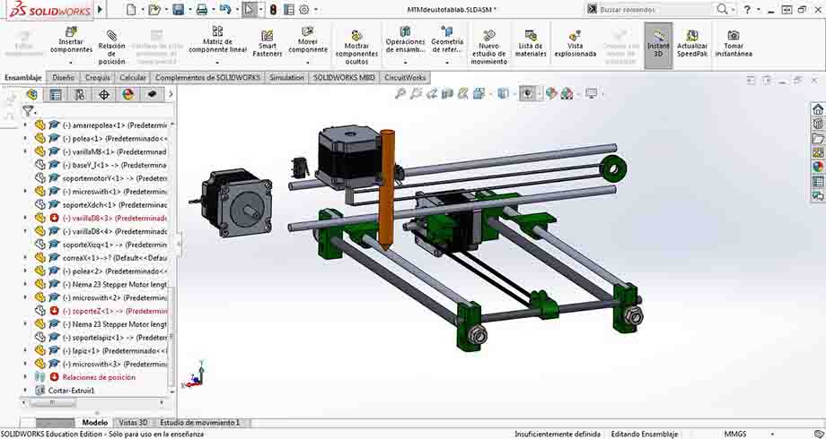
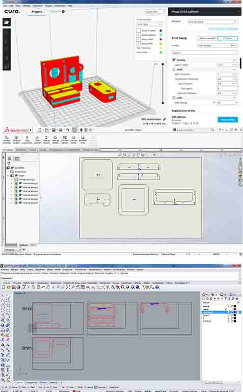
After that, we designed parts we later made by Laser Cut:
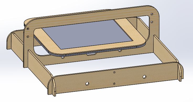
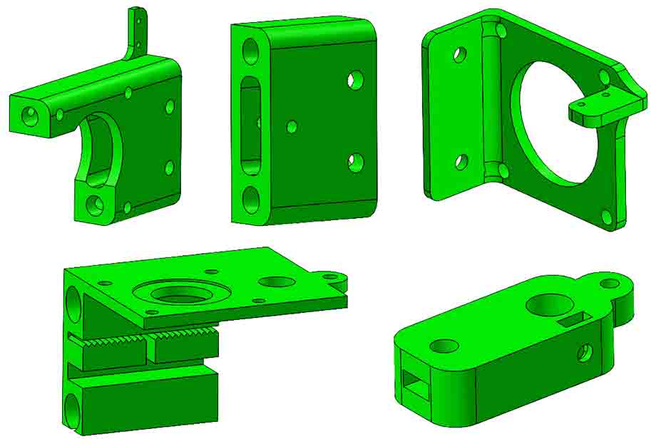
And finally parts we needed to finish the assembly of the 3 axis with the structure. These ones for 3D printing.
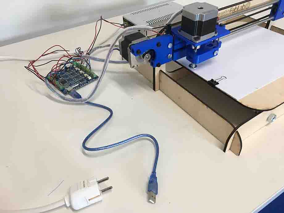
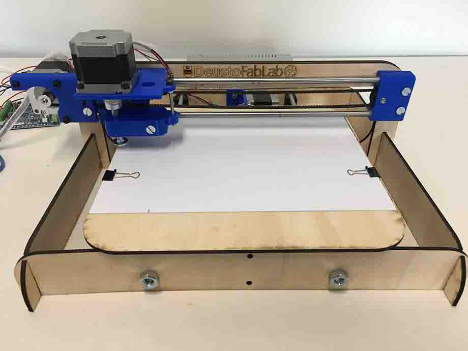
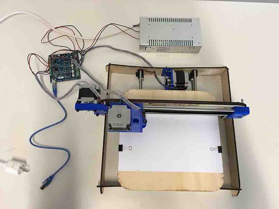
3_ MAKE IT > MOUNT IT
With the 3D design theoretically finished, we made LaserCut and 3D printing parts:

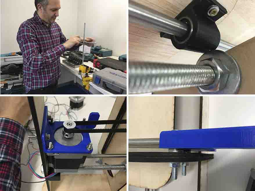
And we assembled everything:
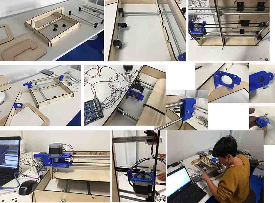
We had have some problems while we were assembling: some threaded rod had to be readjusted, we had to change washers because they collided with other elements, we had to make holes with a drill to pass cables, add washers to equal heights, etc.:
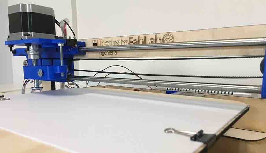
But as it can be seen below, after all we realized to mount it right well, and now, as we said before, we only had to connect it to ChillyPeppr, send the job to draw and pray :)
4_ TEST IT
The following video shows us the first test we did with the machine. It was adjusting the elements manually, without tools, to see if it would work.
It went well, so we adjust every screw using tools, and we send the same spiral again; you see the difference, drawing line is more precise now:
And finally we made a test with FabLabs logo:
:)
5_ FUTURE ACTIONS
After seeing how machine was going on, we made a evaluation, and see some improvements:
		_ FOR A SIMPLE DRAWING MACHINE IS NOT NECESSARY TO HAVE STEPPER MOTOR IN Z AXIS:
			+ It would be better a SERVO; it is only to bringing up and down different pens
		_ HAVING AN STEPPER GIVES US THE OPPORTUNITY TO CONTROL THE HEIGHT OF THE TIP OF THE TOOL:
			+ Make test with, for example, brushes:
			they paint differently depending on how much the tip is squeezed
		_ Z AXIS MOVEMENT AND BRUSH/PEN HOLDER ARE NOT STABLE:
			+ Redesign this two parts to have a better Z up and down guide,
			without vibrations.
		+ Readjust all parts dimmensions to have a general lower vibration (sound).