Electronics Design
Assignments:
Group assignment:
⚡ Use the test equipment in your lab to observe the operation of a microcontroller circuit board (as a minimum, you should demonstrate the use of a multimeter and oscilloscope)
⚡ Document your work on the group work page and reflect what you learned on your individual page
Individual assignment:
⚡ Design a development board to interact and communicate with an embedded microcontroller
Lab equipment
During week #6 I discover a unknown world, the Electronics design world.. in my case I can say that was a funny/not funny experience cause a lot of time the soldier tip ended over my finger but.. (there is always a but thing) I kinda like that world.
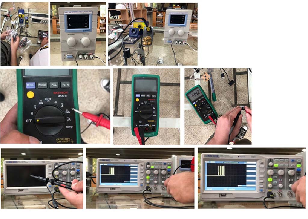
Oscilloscope: SDS 1152CML+
Thecnical facts of this object you can find here (Technical data). With the Oscilloscope we mesure the oscillation of an electric signal, I mean, visualize it. In any case, Abdon also explain to us the part of this (The body, display, buttons, the current probe, etc..) Here you have a video explain to us that

Mulltimeter: MASTECH MS8217 Digital Multimeter
Thecnical facts of this object you can find here (Technical data). With the Mulltimeter you mesure the oscillation of an electric signal, I mean, visualize it. In any case, Abdon also explain to us the part of this (The body, display, buttons, the current probe, etc..) Here you have a video explain to us that
Conclusions: Read and try, thats the correct sequence
What I'd learned? Useful tools but you have to know what you want it to do, cause in other case, it's a waste of time. hahah sorry not sorry. Its going to be fundamental when we start to fabricate the PCB's stuff. Probably I would burn things (I hope not)Problems: The values that the machine gives you always is going to need a knowledge of the signs and the correct way to express the information, but with the infortaion that Abdon (our instructor) gives to us, I survive
The development board from hell
To start design things our instructor Abdon show to us the symbols used to show thing in our board because we have to design a board, a development board whitch interact and communicate with an embedded microcontroller. Construct in an EDA software
At first was tricky and then continued trickier, I mean like a A Series of Unfortunate Events but I could make things
Kicad or Eagle?
To start design things our instructor show to us the symbols used to show thing in our board because we have to design a board, a development board whitch interact and communicate with an embedded microcontroller. Construct in an EDA software
At first was tricky and then continued trickier, I mean like a A Series of Unfortunate Events but I could make things
Kicad: At first I've downloaded this software (Its heavy) and my computer almost die, so I uninstalled to developed easily the homework of that week. Not today Kicad, not today.
Eagle: It was my second choice but at the end I’m happy with it. Of course, following the instructor’s suggestion, I drew on a piece of paper the components of the circuit that I wanted to do before I started Eagle. When I understood how to do things, I started Eagle (Actually, I tried).
Eagle
To start design things our instructor show to us the symbols used to show thing in our board because we have to design a board, a development board whitch interact and communicate with an embedded microcontroller. Construct in an EDA software
At first was tricky and then continued trickier, I mean like a A Series of Unfortunate Events but I could make things
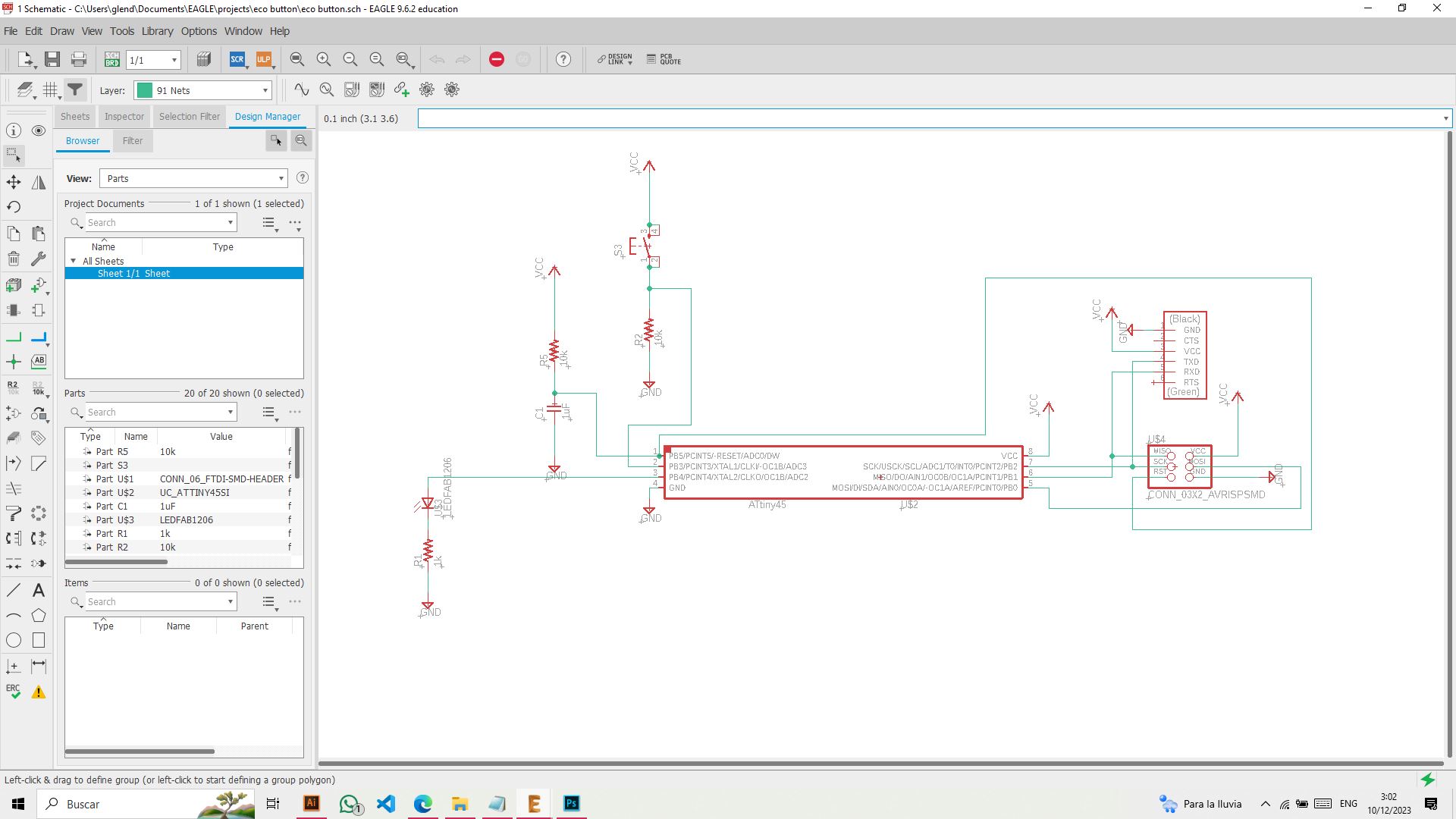
Eagle // Part 1 // Small fights
The difficult thing was to start looking for the elements, I didn't really know the names that are found in Eagle, it was a process of trying one by one the options, asking my colleagues, my innstructor, googlear and still not understand jajajajaa Lie, in the end I could assemble the plate that I had to mechanize.
Eagle //Part 2 // The Revenge of the Software
To facilitate my existence I took as reference the plates given as previous documentation. Back, the choice of paths was changing according to revisions made with the instructor.
Eagle //Part 3 // Everything was fine, we're friends now
In the picture you can see that the routes are already clearer, routes are connected correctly and there are no design errors and connection failures. A tip, once the design process is finished. . . search in the command bar search for ̈Tools - DRC ̈to make an analysis of possible errors and once completed, it can be machined
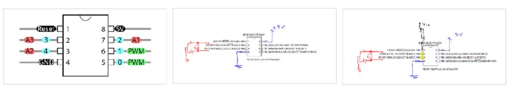
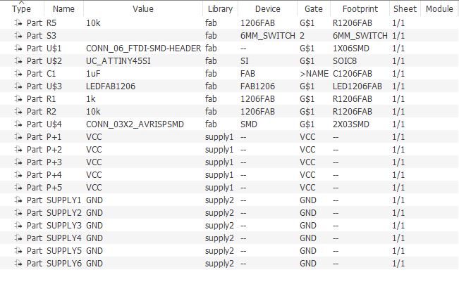
This board consists of a button that is activated, a led that lights up when the order arrives, 2 resistors, 1 capacitor and an ATtiny 45 and the connectors
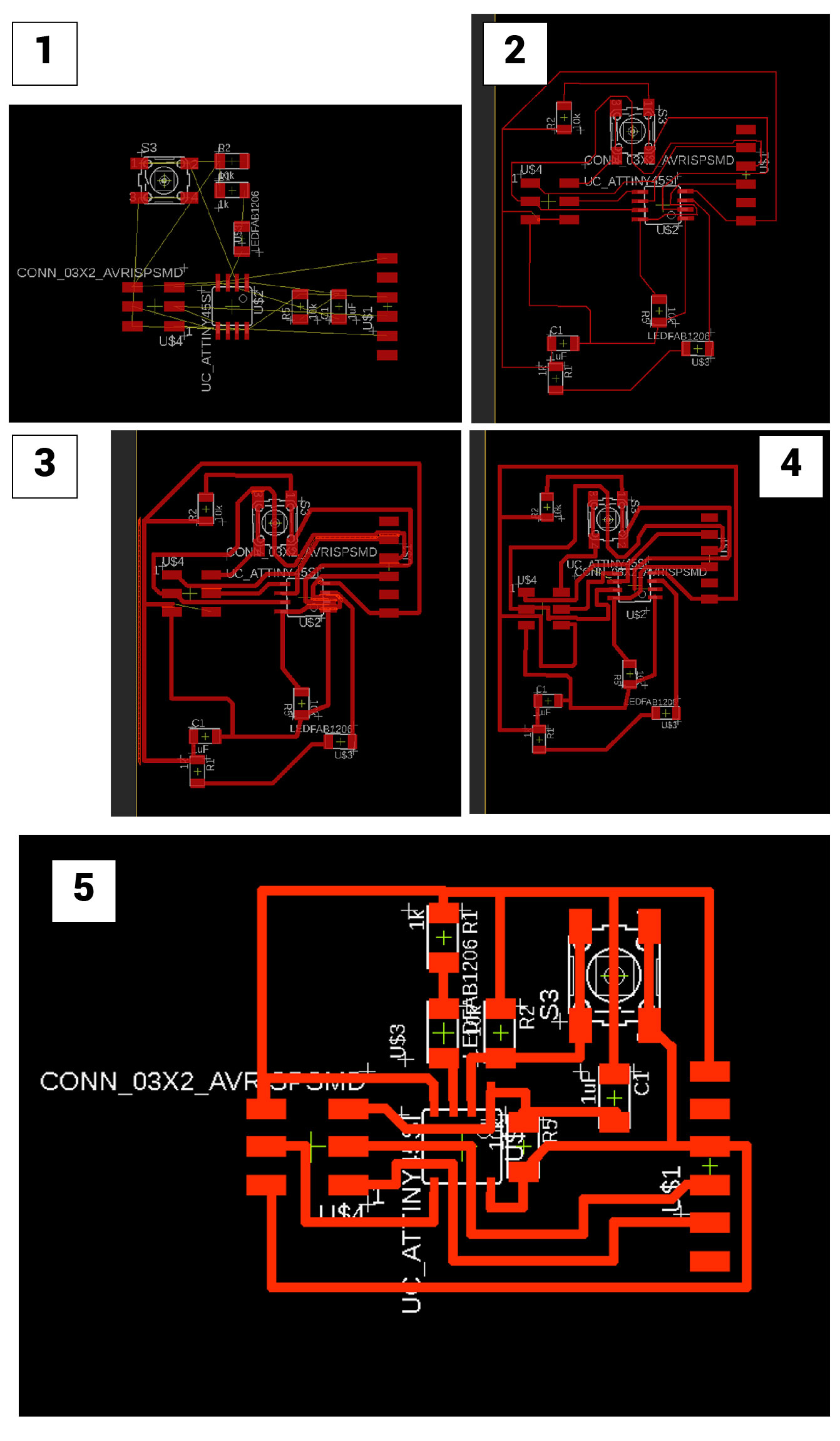
When the connections between components are clear, you can edit the thickness of the lines . Entering the "Properties of Wire" section you choose the thickness and this also depends on the milling bit to be used and the various tolerances that are implicit within the machining process
With the assembling the components paths, the diagramming of these is complicated. That's why I made many combinations and in all missing 1 or 2 did not get to "close"
For example: all GNDs of the components must be connected to the same path, the same goes for VCC and the pins to which they are connected
Sometimes components are not in the Eagle library, so you can look for the component (on the manufacturer's page or in similar libraries) to attach it to the Eagle
Also when the processes mentioned above are finished, it can be exported to GERBER so that it can be manufactured
BOARD FILE