Group assignment.
The Link to group assignment group here.
probe an input device's analog levels and digital signals
Analog signal from Hall effect board To test the analog signal we had a hard time since the one who operates the oscilloscope machine was on leave so we operated on our own by watching youtube tutorials. Here is a useful link about Oscilloscope (Oscilloscope | Definition & Facts | Britannica) According to wikipedia An oscilloscope (informally scope or O-scope) is a type of electronics test instrument that graphically displays varying electrical voltages as a two-dimensional plot of one or more signals as a function of time. The main purposes are to display repetitive or single waveforms on the screen that would otherwise occur too briefly to be perceived by the human eye. The displayed waveform can then be analyzed for properties such as amplitude, frequency, rise time, time interval, distortion, and others. Originally, calculation of these values required manually measuring the waveform against the scales built into the screen of the instrument.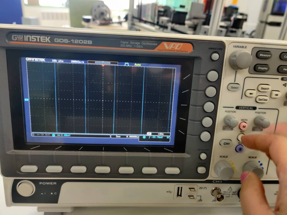
Below here is the video of PIR while checking for the signals and the serial monitor motion that has been detected while coding, for PIR coding we did on ourselves. And Digital signal for capacitive test you can see below the analog wave of capacitive and its stimulation on the oscilloscope. We got the code from our instructor, he helped us to get the code.
Input devices.
DS18B20 sensor since this sensor is a waterproof sensor so for my final project I thought of using a sensor
So for input week measure something: add a sensor to a microcontroller board that you have designed and read it so for my input week I tried to use the DS18B20 that can read temperature and i thought that it is related to my final project so i tried using this sensor. According to google The packaged DS18B20 can be used for temperature measurement in cable trenches, blast furnace water circulation, boiler, machine room, agricultural greenhouse, clean room, ammunition storage, and other non-limit temperature occasions. It is a wear-resistant and impact-resistant temperature sensor with small size and various packaging forms. below here is an image of the sensor that i am using this week, so as you can clearly see the pin out diagram below and picture source for DS18B20 sensor is from google.
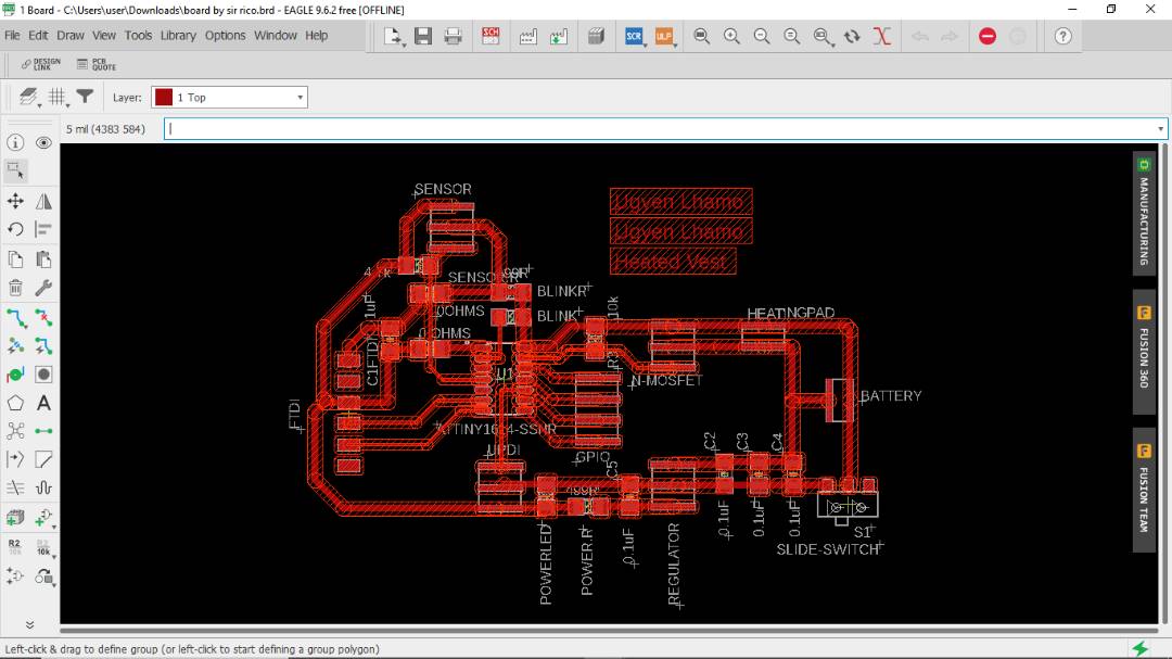
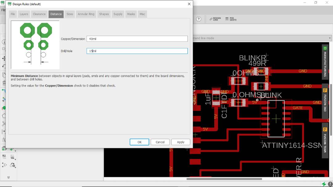
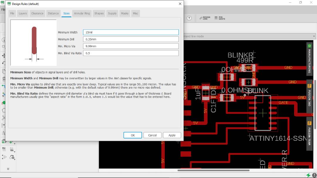
Below here is the schematic and board design on Eagle.
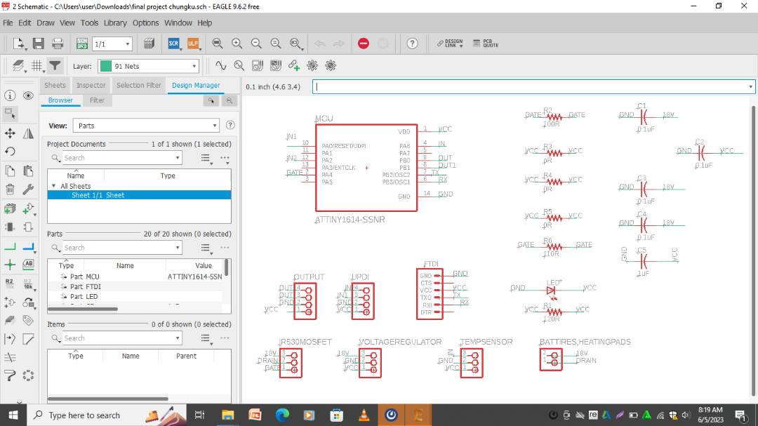
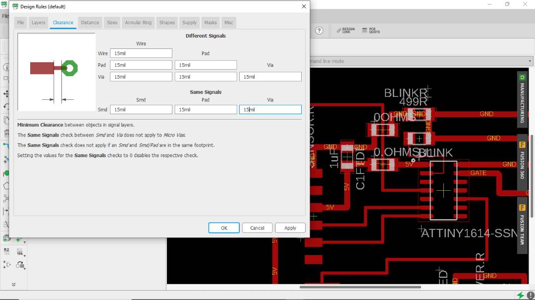
Eagle settings of the width and the size of the connection lines.
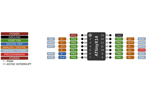
Below here is the pinout diagram for Attiny1614
The connections.
1st pin of the sensor is vcc of the FTDI
Second is the GND pin which goes to the GND of the MCU
3rd is empty for dht22 sesnor and for DS18B20 sensor it is the data pin to the pin 2 of the MCU
4th pin for DHT22 pin is the signal pin which goes to the pin 2 of the mcu
now to set up on arduino ide and the settings. Before that include the library below;#include < OneWire.h>
#include < DallasTemperature.h >
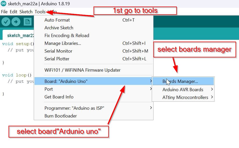
- Now let us set up on arduino ide for the programming.
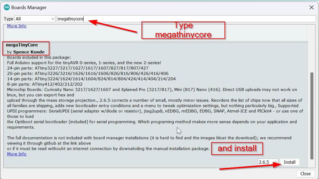
- Then Go to tools and select the board manager there.
- after that go to the library and search megaTiny core.
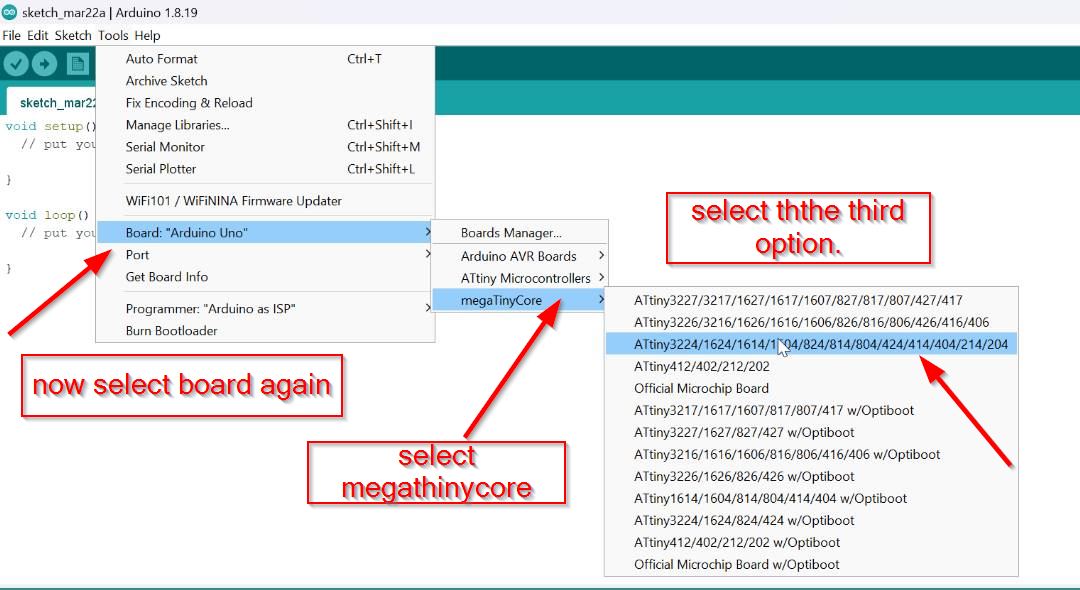
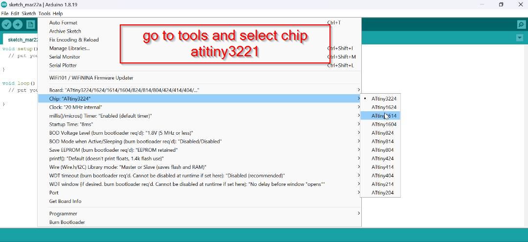
After that select the board to Attiny 1614.
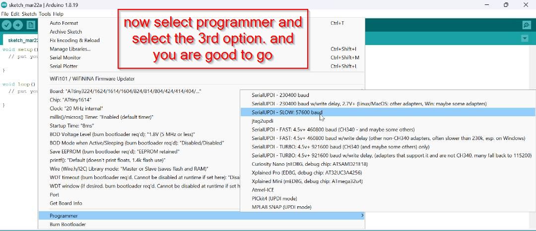
Then select the programmer as shown below and don't forget to select the port .
As you can see that the sensor is working and even the code is compiled and I got the code from google and the link is Here.
Below here is the code for temperature sensor DS18B20
      #include <OneWire.h>
      #include <DallasTemperature.h>

      // Define to which pin of the Arduino the 1-Wire bus is connected:
      #define ONE_WIRE_BUS 2

      // Create a new instance of the oneWire class to communicate with any OneWire device:
      OneWire oneWire(ONE_WIRE_BUS);

      // Pass the oneWire reference to DallasTemperature library:
      DallasTemperature sensors(&oneWire);

      void setup() {
        // Begin serial communication at a baud rate of 9600:
        Serial.begin(9600);
        // Start up the library:
        sensors.begin();
      }

      void loop() {
        // Send the command for all devices on the bus to perform a temperature conversion:
        sensors.requestTemperatures();

        // Fetch the temperature in degrees Celsius for device index:
        float tempC = sensors.getTempCByIndex(0); // the index 0 refers to the first device
        // Fetch the temperature in degrees Fahrenheit for device index:
        float tempF = sensors.getTempFByIndex(0);

        // Print the temperature in Celsius in the Serial Monitor:
        Serial.print("Temperature: ");
        Serial.print(tempC);
        Serial.print(" \xC2\xB0"); // shows degree symbol
        Serial.print("C  |  ");

        // Print the temperature in Fahrenheit
        Serial.print(tempF);
        Serial.print(" \xC2\xB0"); // shows degree symbol
        Serial.println("F");

        // Wait 1 second:
        delay(500);
      }
DHT22 Temperature and humidity sensor.
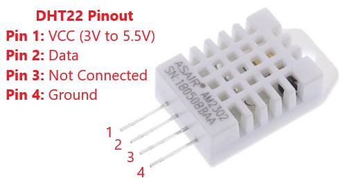
Since we were to use two output so I used DHT22 temperature and humidity sensor. it uses capacitive humidity sensor and measure the surroundings's air and a thermistor to measure the surrounding air and splits out a digital signal on the data pin. this sensor has three pin out which is GND, VCC , 3rd pin doesn't have anything and 4th one is signal pin. Below here is the pinout for the sensor i got the image from google.
// REQUIRES the following Arduino libraries:/
// - DHT Sensor Library: https://github.com/adafruit/DHT-sensor-library
// - Adafruit Unified Sensor Lib: https://github.com/adafruit/Adafruit_Sensor
So here is the code i got from google and i tried to see if the temperature sensor works with my board and what i found out was it worked weell and was reading the temperature. you can even see the changes in the temperature since i placed a frozen egg near the temperature sensor to see the temperature drop.
  // Example testing sketch for various DHT humidity/temperature sensors
  // Written by ladyada, public domain

  // REQUIRES the following Arduino libraries:
  // - DHT Sensor Library: https://github.com/adafruit/DHT-sensor-library
  // - Adafruit Unified Sensor Lib: https://github.com/adafruit/Adafruit_Sensor

  #include "DHT.h"

  #define DHTPIN 9    // Digital pin connected to the DHT sensor
  #define DHTTYPE DHT22   // DHT 22  (AM2302), AM2321

  int heatpadPin = 8;

  // Connect pin 1 (on the left) of the sensor to +5V
  // Connect pin 2 of the sensor to whatever your DHTPIN is
  // Connect pin 4 (on the right) of the sensor to GROUND and leave the pin 3 EMPTY (if your sensor has 4 pins)
  // Connect a 10K resistor from pin 2 (data) to pin 1 (power) of the sensor

  // Initialize DHT sensor.
  // Note that older versions of this library took an optional third parameter to
  // tweak the timings for faster processors.  This parameter is no longer needed
  // as the current DHT reading algorithm adjusts itself to work on faster procs.
  DHT dht(DHTPIN, DHTTYPE);

  void setup() {
    Serial.begin(9600);
    Serial.println(F("DHTxx test!"));

    dht.begin();
    pinMode(heatpadPin, OUTPUT);

    digitalWrite(heatpadPin, LOW);

  }

  void loop() {
    // Wait a few seconds between measurements.
    delay(2000);

    // Reading temperature or humidity takes about 250 milliseconds!
    // Sensor readings may also be up to 2 seconds 'old' (its a very slow sensor)
    float h = dht.readHumidity();
    // Read temperature as Celsius (the default)
    float t = dht.readTemperature();
    // Read temperature as Fahrenheit (isFahrenheit = true)
    float f = dht.readTemperature(true);

    // Check if any reads failed and exit early (to try again).
    if (isnan(h) || isnan(t) || isnan(f)) {
      Serial.println(F("Failed to read from DHT sensor!"));
      return;
    }

    digitalWrite(heatpadPin,LOW);
      delay(3000);

    Serial.println("Heat Pad ON");
    Serial.println(" ");

    // Compute heat index in Fahrenheit (the default)
    float hif = dht.computeHeatIndex(f, h);
    // Compute heat index in Celsius (isFahreheit = false)
    float hic = dht.computeHeatIndex(t, h, false);

    Serial.print(F("Humidity: "));
    Serial.print(h);
    Serial.print(F("%  Temperature: "));
    Serial.print(t);
    Serial.print(F("°C "));
    Serial.print(f);
    Serial.print(F("°F  Heat index: "));
    Serial.print(hic);
    Serial.print(F("°C "));
    Serial.print(hif);
    Serial.println(F("°F"));

    digitalWrite(heatpadPin,HIGH);
    delay(3000);
    Serial.println("Heat Pad OFF");
    Serial.println(" ");
  }
Below here is the video that i tried with the egg placed on the sensor. The egg was kept in the freezer so it can be cold enough to trigger the sensor.