Output Devices.
The Link to our group assignment is here.
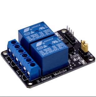
So this week was output week were all of us were asked use output to the board that we designed.I designed a board for the output week, and i used a 2 relay module since I got it form our lab. According to google Relay are just like any other switch which can either make or break a connection, that is it can either connect two points or disconnect it, therefore relays are commonly used to turn on or off an electronic load.Some important things to keep in mind are;1.check the LED before using it.2.Digital power supply is great as it shows both voltage and current, this week for the assignment we were to try an output device on our board and make it communicate so i used a 2 relay module and when the reset button is on there will be blink after every .So this week group assignment was to measure the power consumption of an output device.To do this, this was the formula:
P = I.V
Where P = power consumped (W)
I = Current (A)
V = Voltage (v)
Individual assignment.
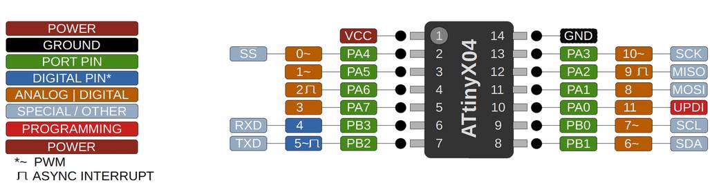
Add an output device to a microcontroller board you’ve designed, and program it to do something. Group Assignment: Measure the power consumption of an output device.I used relay as an output since i tried with PIR and led which was not an input it was the same board Attiny 1614 for programming and below here is the pin-out diagram i got from google.
This is my board that I designed on eagle and this is the png image.his is 2 relay channel i used this week, i used my board that I designed this week. I got help from my Instructor who help me with coding and he even helped me with the board connection.Below here is the video of relay module working since my board didn't work in past few days and was very frustrating and finally when it worked i was so happy and started documenting. The out put is relay and i kept the delay of 2000 so after every 2 sec there it will blink. As you can see below
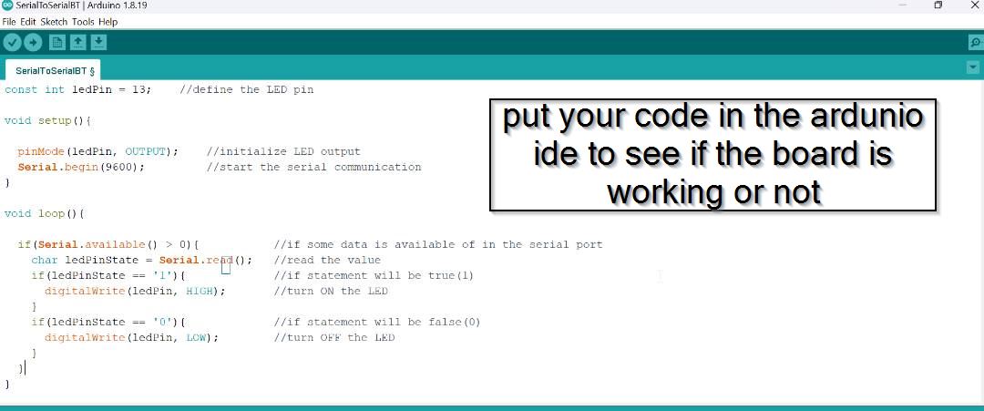
- Now let us set up on arduino ide for the programming.
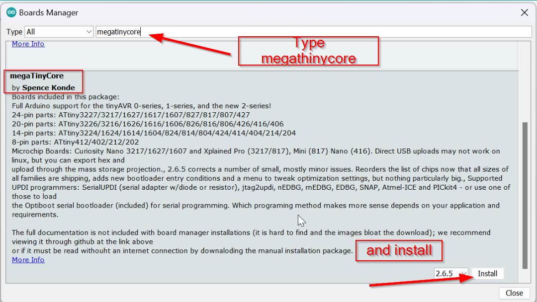
- Then Go to tools and select the board manager there.
- after that go to the library and search megaTiny core.
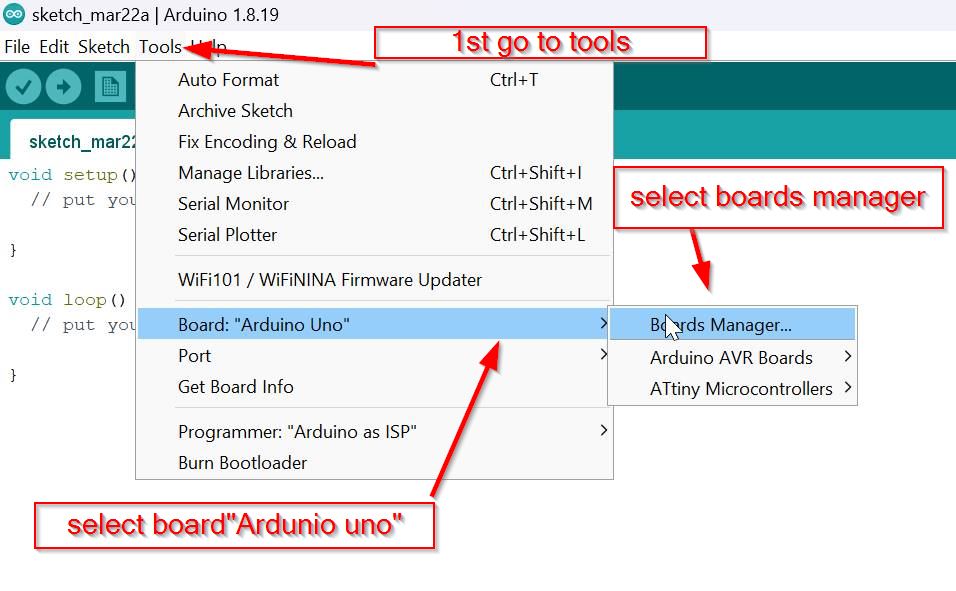
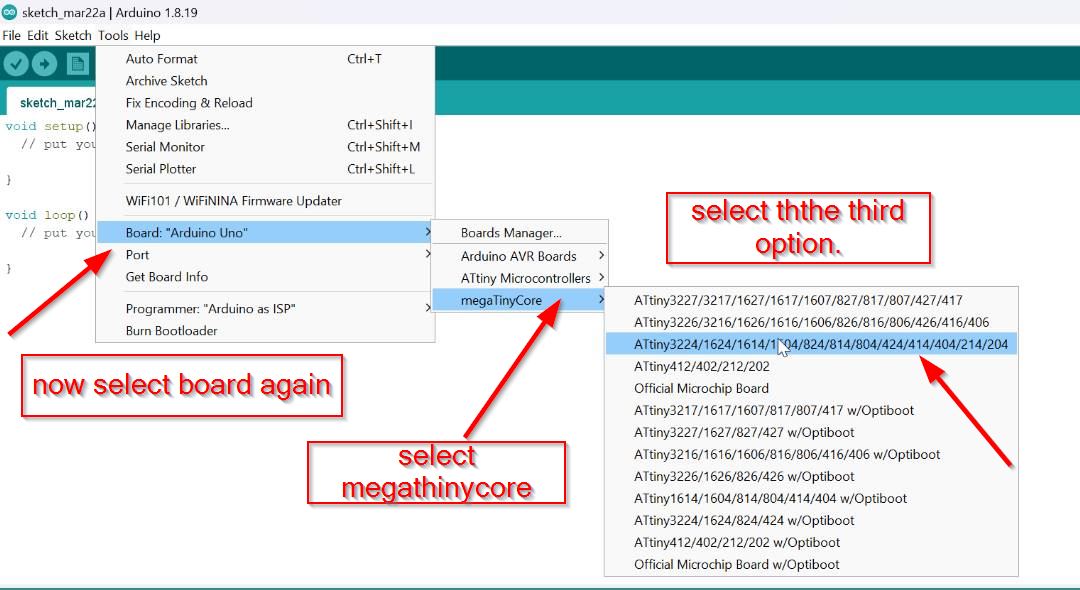
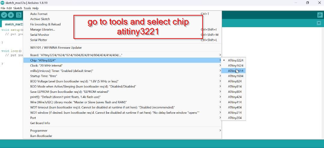
After that select the board to Attiny 1614.
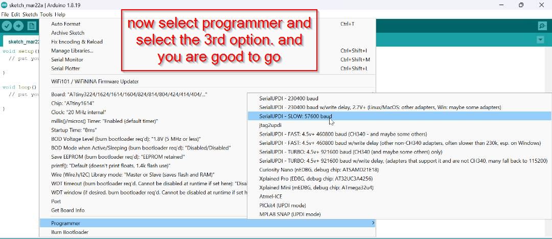
Then select the programmer as shown below and don't forget to select the port .
• This is the link i got from the google download from here.
• Here is the DHT11 library
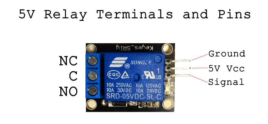
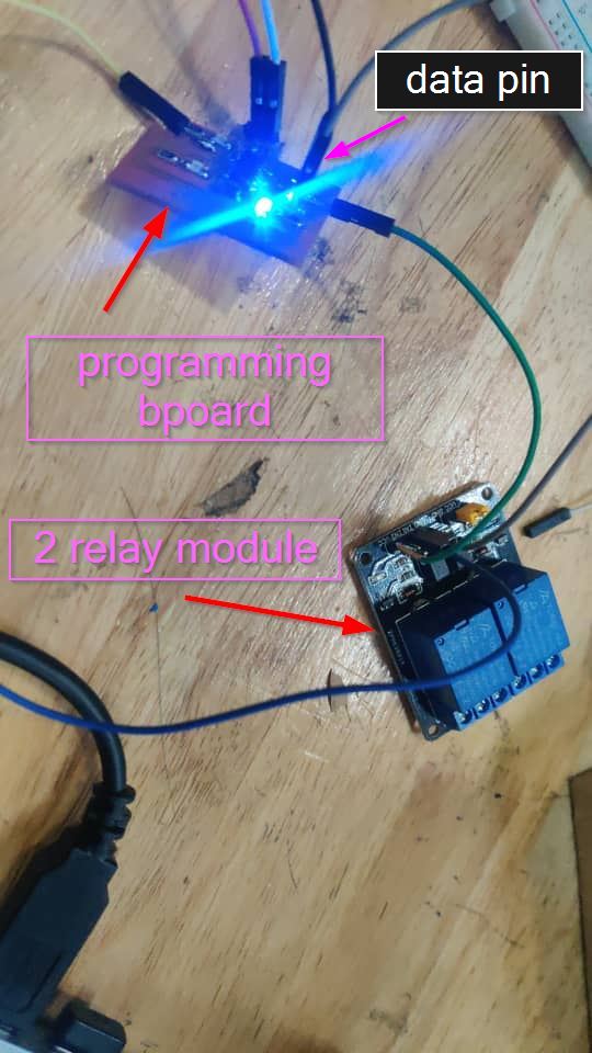
Connection.
Board data pin Pin(Attiny1614 Pin) GND on the relay pin
GND of Output Pin to GND of relay pin VCC of Output Pin to VCC of the relay pin.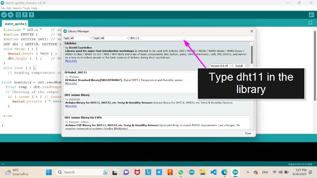
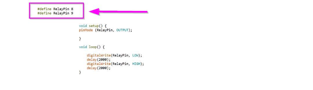
Below here is the code for my relay that worked and i got the code from last year's student, Dorji Tshering Drugyal. you can check out his website here
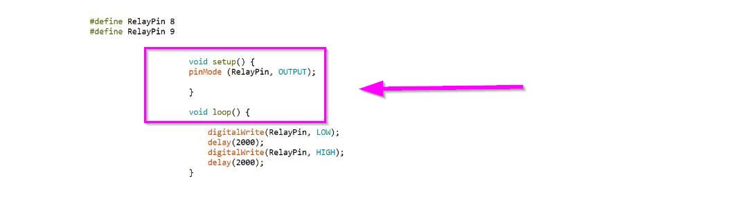
#define RelayPin 8
#define RelayPin 9
void setup() {
pinMode (RelayPin, OUTPUT);
}
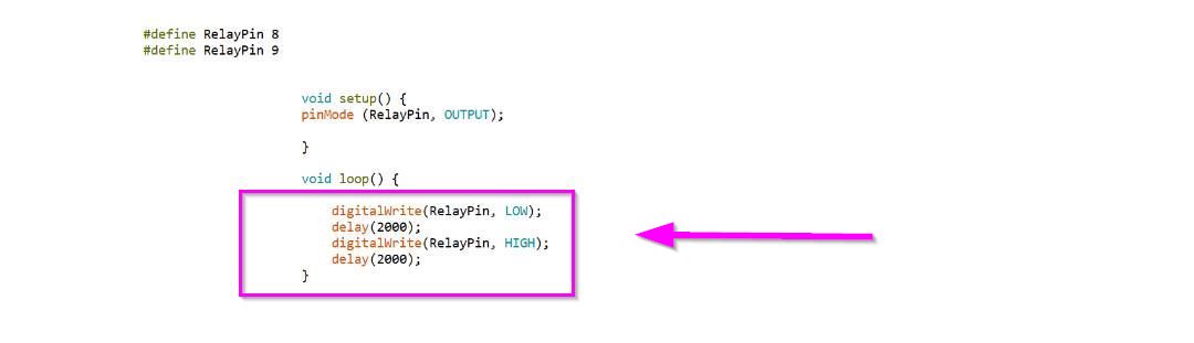
void loop() {
digitalWrite(RelayPin, LOW);
delay(2000);
digitalWrite(RelayPin, HIGH);
delay(2000);
}
Code explanation in brief.
The "#define" command in Arduino IDE is used to create a constant variable. When you use "#define" to create a constant, you give it a name, and then assign it a value. This variable can then be used throughout your code, and if you need to change the value of the constant, you only need to change it in one place (where it is defined) rather than changing it everywhere it is used. The "pin" you're referring to is likely a digital input/output pin on the board. By using "#define" to create a constant for a pin, you can assign a name to the pin and use that name throughout your code, rather than having to remember the specific number of the pin. For example, you might use "#define LED_PIN 13" to assign the name "LED_PIN" to digital pin 13 on your board. Then, throughout your code, you can use "LED_PIN" to refer to that specific pin, rather than having to remember that it's pin 13.
In Arduino IDE, "void setup()" is a function that is called once when the microcontroller first starts up. It's typically used to initialize variables, set pin modes, and perform other setup tasks that only need to be done once. "PinMode" is a command in Arduino IDE that is used to set the mode of a specific digital input/output pin on the board. When you use "PinMode" to set a pin to "OUTPUT" mode, you're telling the microcontroller that you want to use that pin to output a voltage (i.e. to control something like an LED or a relay). So, "void setup(){ PinMode (relay pin outout)" is telling the Arduino board to set the pin that controls the relay to "OUTPUT" mode, which allows it to output a voltage to control the relay.
In Arduino IDE, "digitalWrite" is a command that is used to write a digital value (either HIGH or LOW) to a specific digital input/output pin on the board. When you use "digitalWrite" to set a pin to "HIGH", you're telling the microcontroller to output a voltage of 5V on that pin. When you use "digitalWrite" to set a pin to "LOW", you're telling the microcontroller to output a voltage of 0V (ground) on that pin. This command is often used to control LEDs, relays, and other digital devices that can be turned on and off using a voltage signal. For example, if you wanted to turn on an LED connected to digital pin 13 on the board, you would use the command "digitalWrite(13, HIGH)" to output a voltage of 5V on that pin and turn on the LED.
Working video
With every 2000 delay the relay blinks after every 5 second.
Board design files