Electronics designing
Difference between Analog and Digital signal
| Analog Signal | Digital Signal |
|---|---|
| It is a continous wave that changes smoonthly over time | where as in digital it can only have a limited number with defined values |
| it is time varying and continous | Has two or more states in binary form |
| uses continuos values to represent data | in digital it uses discrete to represent data |
| Components Eg; Resistor, Capacitor,Inductors Diode are used in analog circuit | where as in Digital; Transistor, logic gate MCU are used |
| uses more power | uses less power |
| Temperature,pressure, flow measurement are the example of analog signal | valve feed back , motor start , trip etc are the examples for digital |
Group assignment
Link to our group assignment is here
This week we were to Design our own board using any software whether it can be Eagle and KiCad.For me during my pre fab course we were introduced to Eagle so i was much familiar to Eagle software. So for my this week assignment i completed using Eagle software to design a pcb.
what is Eagle?
According to google; EAGLE is electronic design automation (EDA) software that lets printed circuit board (PCB) designers seamlessly connect schematic diagrams, component placement, PCB routing, and comprehensive library content.
Download Eagle software from google
Click here to download.
Eagle software was not really a new software for me so i did not had much trouble regarding on designing our own PCB. So for which which components you have to use, you can simply refer from the fab academy website. For me I downloaded it for reference.
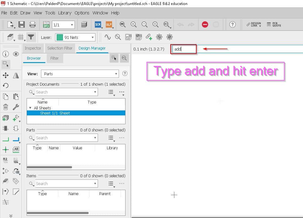
Open eagle in your desktop and choose Schematic Design.
Next go there is a space and right above that you have an option to click, just type add
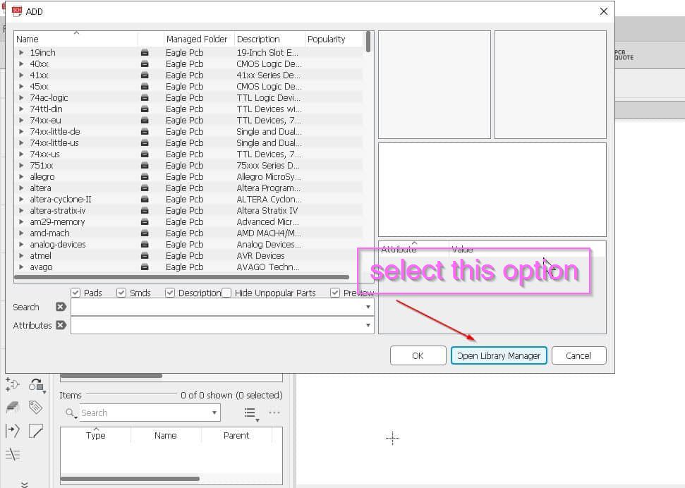
After that go to open library manager and click on it
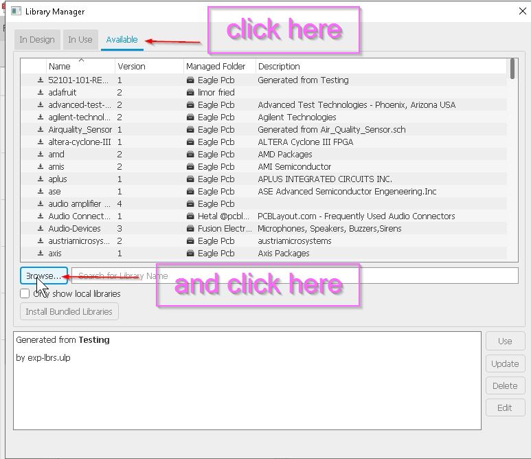
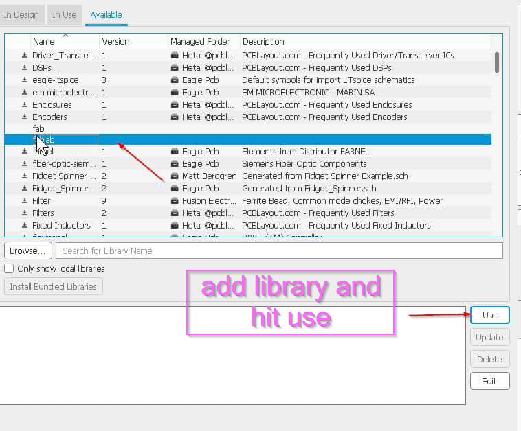
Click on Available and then browser as shown below.
Now just add these library.And hit open.
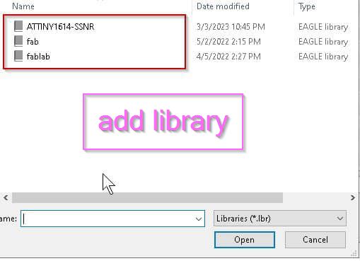
Add the library Fab and fab lab and even Attiny 1614. And click on use.
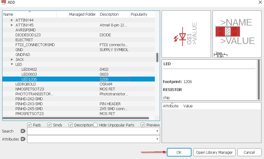
Now add the components.And click ok.
For that you can see at the right side, at the top is to group the components, next to move and to rotate and in the next option there is copy and paste option,and delete option and the most important thing is for labelling the parts.
Now label the components.For my components i have used
MCU= Attiny1614
FTDI (Fab-lab)
UPDI
Led (2numbers)
Resistor 10 k ohms
Capacitor
omoron switch.
6mm switch.
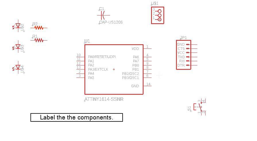
Now after adding the components and labelling it
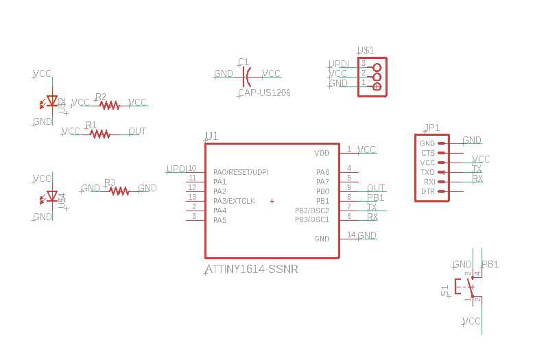
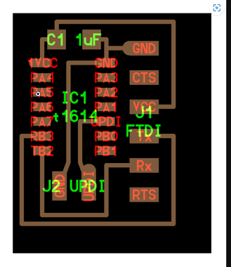
Go to board and ypu will get something like this
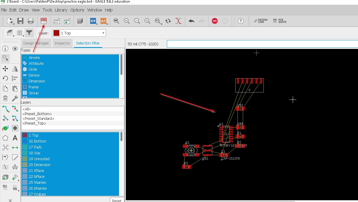
You have to arrange the components without overlapping it and make the traces for that just drag the components on the blank area.
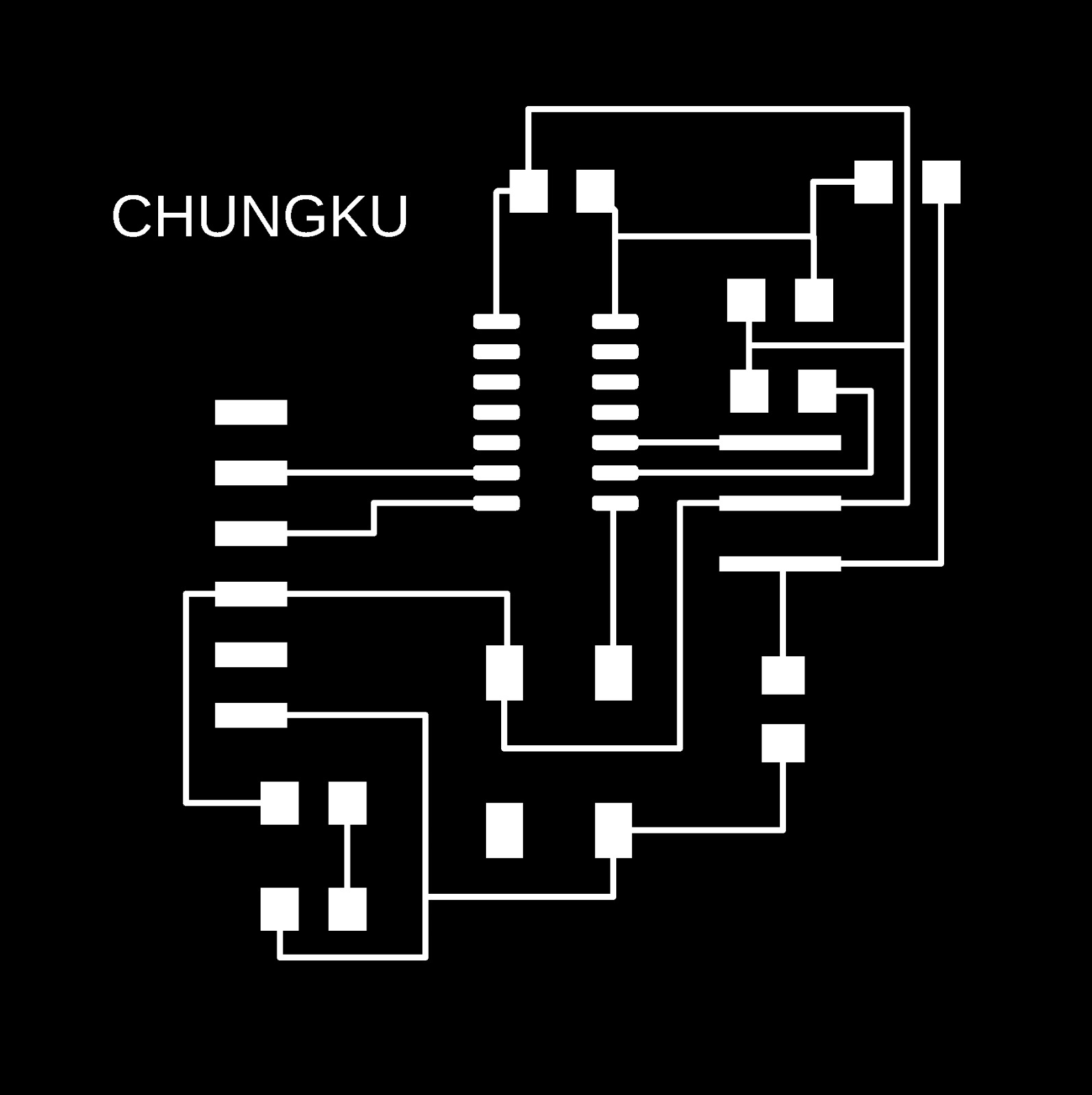
Now after you are done with traces you will get this kind of traces after you have given the right part and connections.our instructor informed us to ensure that no traces/routes run in between the controller pins and no more than 2 routes should run under any components. so i started routing and it took me almost a day to optimize my board design until it is finally done.so here is my traces.
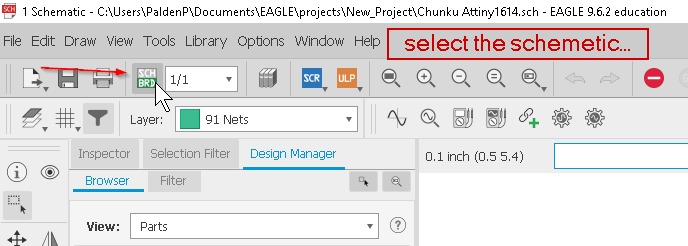
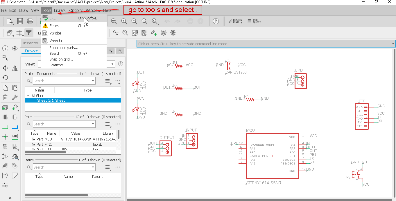
After you are done with arranging your component in the right place you should check for DRC or error which is right at the top of your design click on the tools and select ERC or error as below.
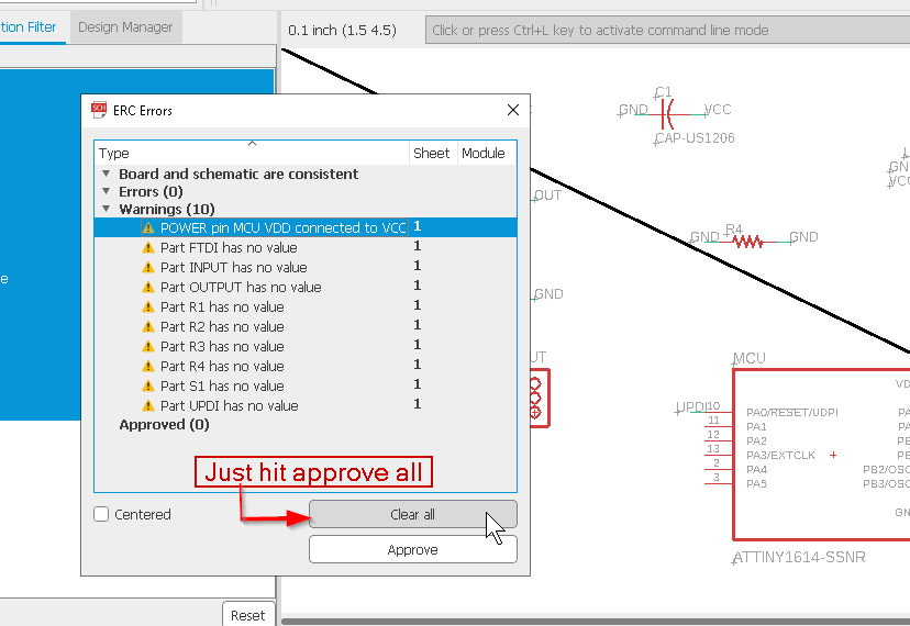
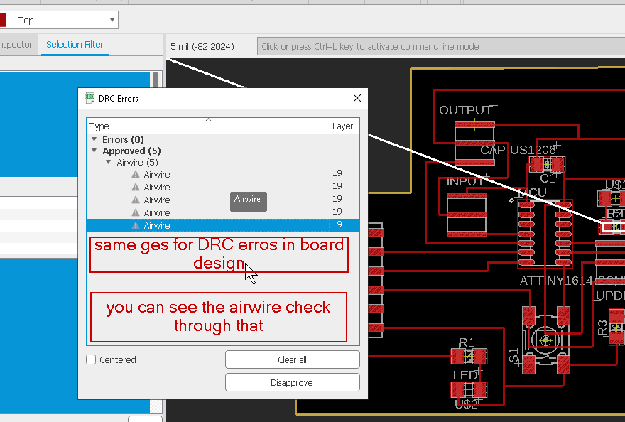
Now see where are your erros and just hit the clear option. And you can even check on the board design, the first one is the schematic design and second one is the board design so in the board design you can even click on the DRC or erro to check the erro and just hit approve the Airwire.
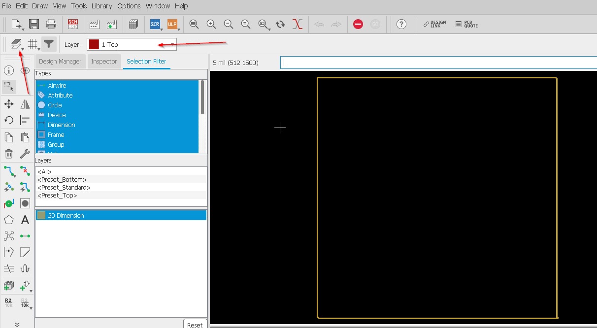
Go to view option after that Select layer setting hide all layers except for dimensions layer for border traces and top layer for design traces as shown below
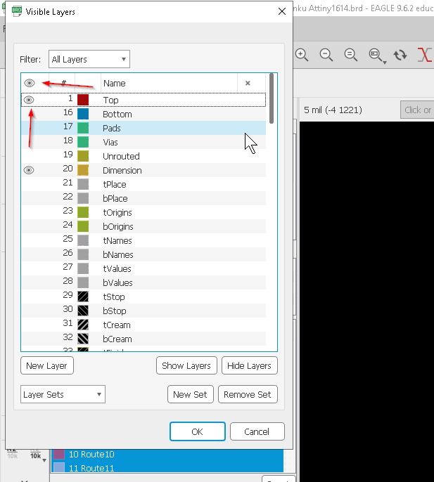
Now you will get this kind of design and for outline just hide all the parts just unhide the dimension.
This is for outline traces
Below here is the youtube tutorial that is really helpful for the beginners to know how to use eagle for me during my pre fab designing board and electronic was very difficult since i was not from any engineering background although learning form youtube and google made me more interested to design and make my own board which was very fun learning and interesting. When it comes to microcontroller (MCU) boards, commercial boards are typically designed to be more user-friendly and accessible for beginners, while own design boards are usually more customizable and tailored to specific needs. Commercial boards often come with pre-installed software and libraries, making them easier to use, while own design boards require more technical knowledge and programming skills. Additionally, commercial boards are often more expensive, while own design boards can be cheaper but require more time and effort to create.
Things needs to be improved for manufacturing later on. When sending your own MCU board to be manufactured, there are a few things that you may want to consider improving: 1Power consumption: Make sure that your board is designed to consume as little power as possible to extend battery life and reduce operating costs.
.2. Size: Consider the size of your board and whether it can be made smaller without sacrificing functionality. Smaller boards can be more convenient to use and transport. .3. Compatibility: Ensure that your board is compatible with other hardware and software that it may need to interact with, such as sensors or communication protocols. .4. Robustness: Make sure that your board is designed to be durable and reliable, with appropriate protection against power surges, ESD, and other hazards. .5. Cost: Consider the cost of manufacturing your board and whether there are any ways to reduce costs without sacrificing quality or functionality.some general things that one might learn from designing their own board on Eagle:
1. Schematic design: You will learn how to create a schematic diagram of your circuit design, including the components and connections between them. 2. PCB layout: You will learn how to lay out the printed circuit board (PCB) for your design, including the placement of components and copper traces. 3. Design rules: You will learn how to set design rules for your board, such as minimum trace width, clearance, and via sizes. 4. Component selection: You will learn how to select appropriate components for your design, taking into account factors such as size, cost, and performance. 5. Design for manufacturing: You will learn how to design your board with manufacturing in mind, including considerations such as panelization and assembly processes. 6. Troubleshooting: You will learn how to troubleshoot issues that may arise during the design process, such as design rule violations, connectivity issues, and power supply problems.