Embeded programming.
For this week (week 4) we learned about embeded programming, our local instructor gave us group assignment and induvidual assignment.
group assignment
Link to our group assignment is here
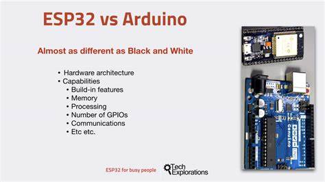
According to google ESP32 has 18 ADCs channels while Arduino Uno has only six. ESP32 comes with 48 GPIO pins while Uno has only14 digital input/output pins and 6 analog pins. The ESP32 board is cheaper than the Arduino Uno.
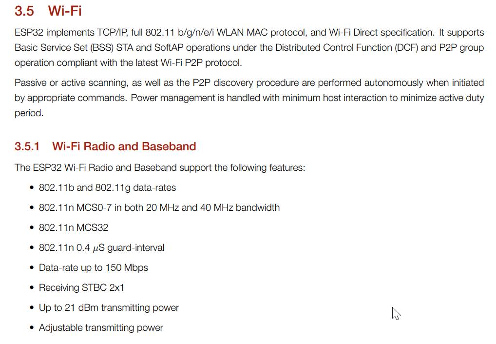
ESP32 have 32-bit microcontroller
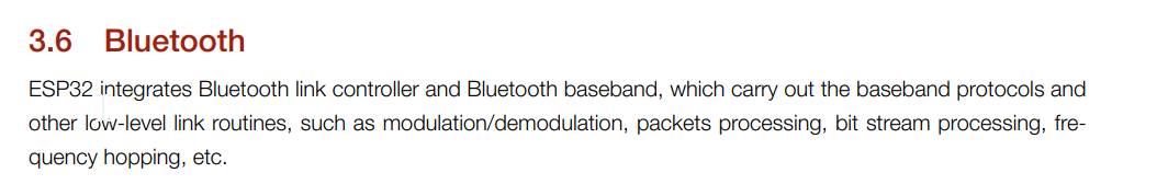
Dual Wi-Fi and Bluetooth support
Works on low voltage level (3.3V)
ESP32 has 18 ADCs channels while Arduino Uno has only six
ESP32 comes with 48 GPIO pins while Uno has only14 digital input/output pins and 6 analog pins
The ESP32 board is cheaper than the Arduino Uno
In the lab we were introduced to tinkercad by our instructor although we used this online software earlier in 3D design but for now we were supposed to used for correct circuit connection before doing it practicle . Tinkercad is used for simple 3D design and used inorder to see the circut connection. it is an free online computure aided design (CAD) program enabling users to modify 3D print object as said earlier,it even helps to experiment with circuit to learn using blocks. one intresting thing i learn in week 3 class was that after the correct connection of your circuit you can even get the code from the block option, by selection text option.
Now let's see the steps in detial.
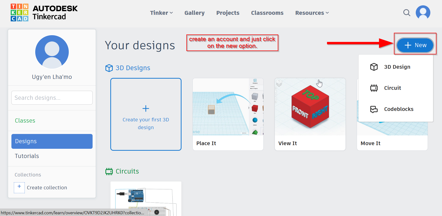
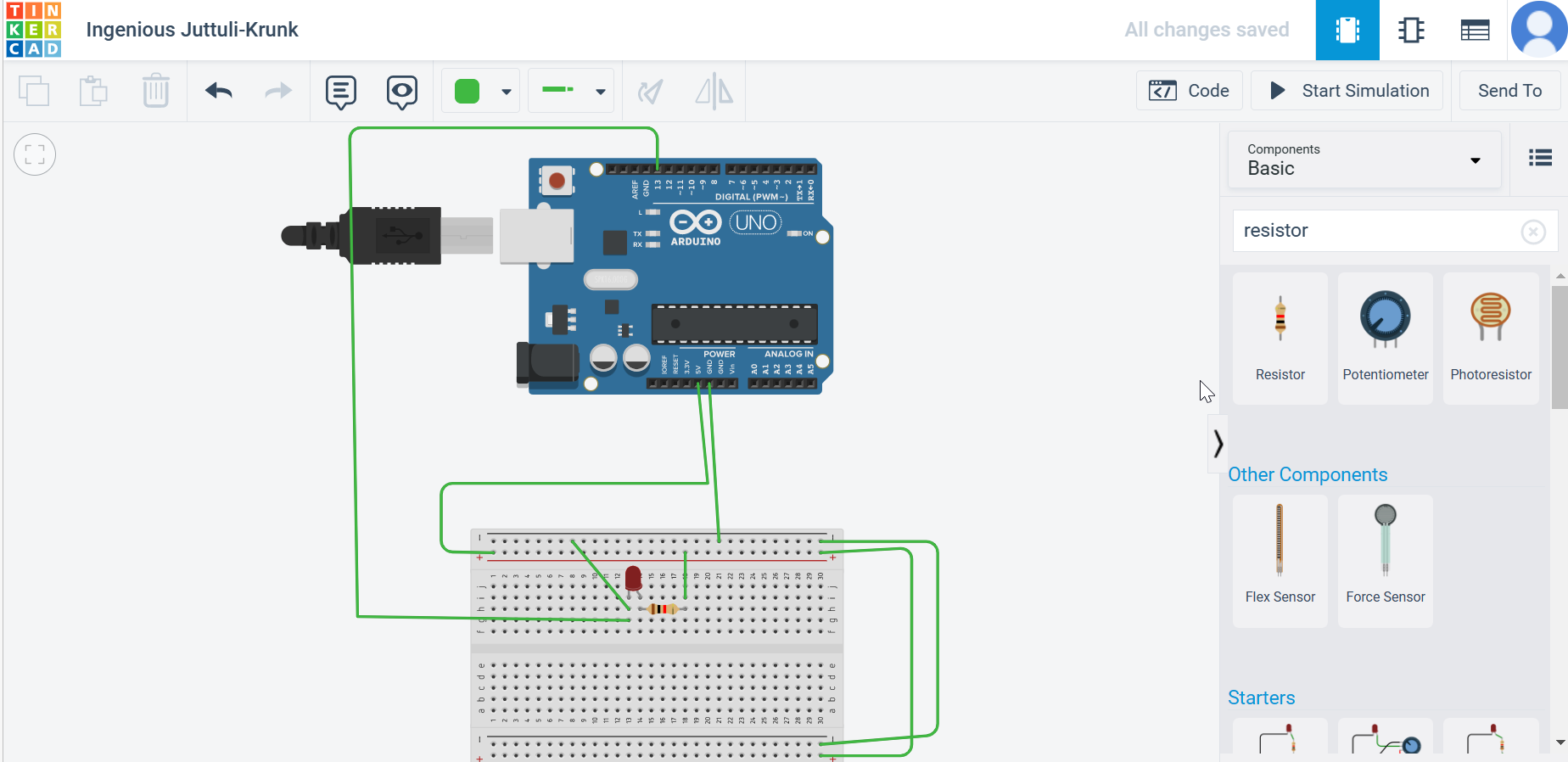
open tinkercad in your desktop by going to google, since it is a free online design software you don't have to download. Just create an account and start playing with the components.On the right side as you can see a bar that has a search button, there you can search for what component you want to experiment.
I used
1) A simple Led,
2) Ardunio
3) Bread board
4) Resistor and
5) Jumper wires.
Steps to circuit design.
So before designing a circuit we have to create an account. After that click on circuit design.
As you can see below these are the components used for simple circuit design.
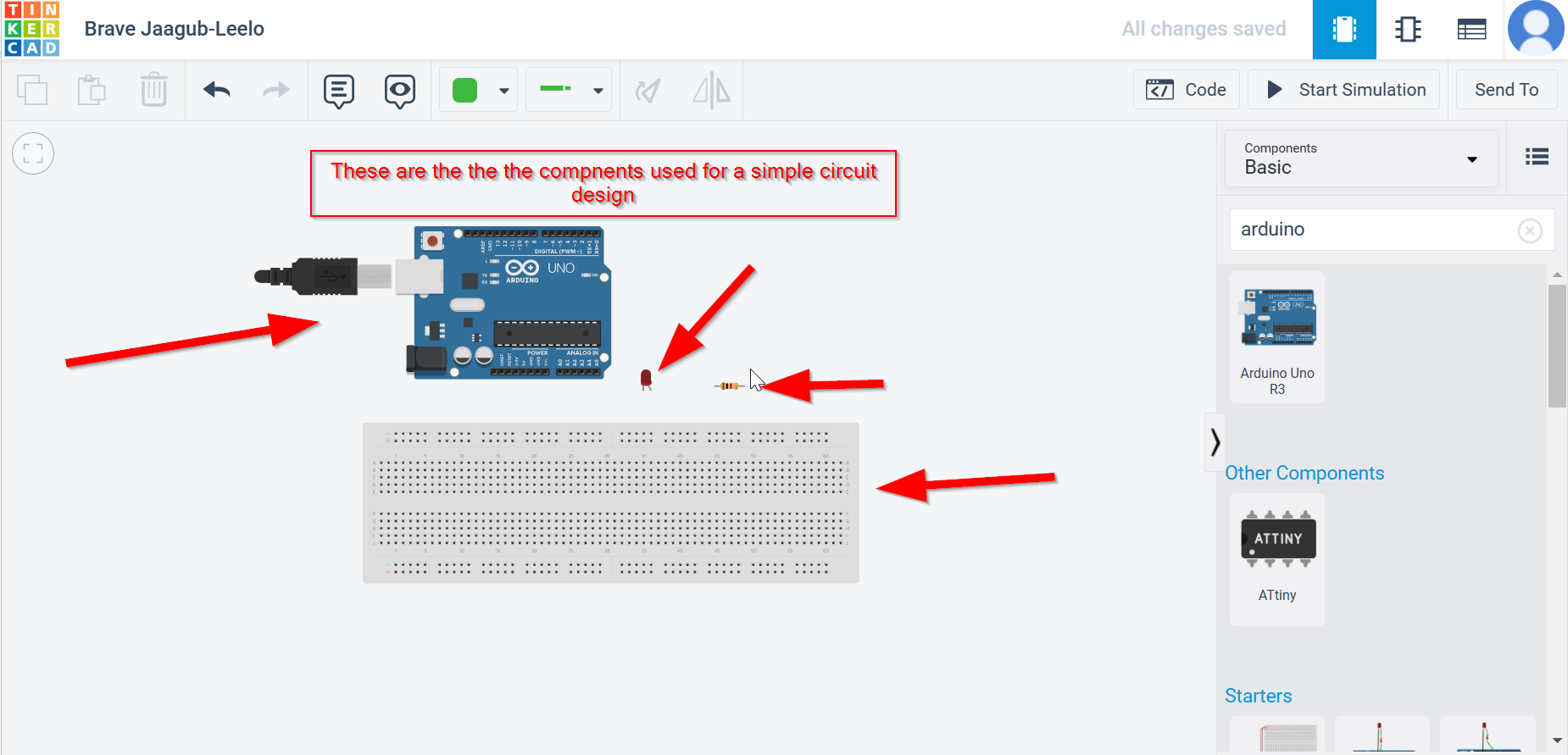
you can get these component from the right side of your desktop frorm the search bar
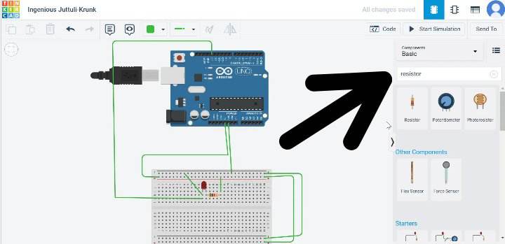
here is the simple circuit conection using the component that i have mentioned above.
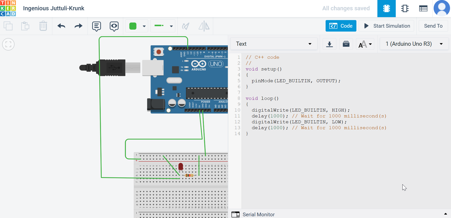
As you can see below the circuit is complete so you can go to the right side and start stimulating.
after doing that you can stop the stumilation and see the coding.
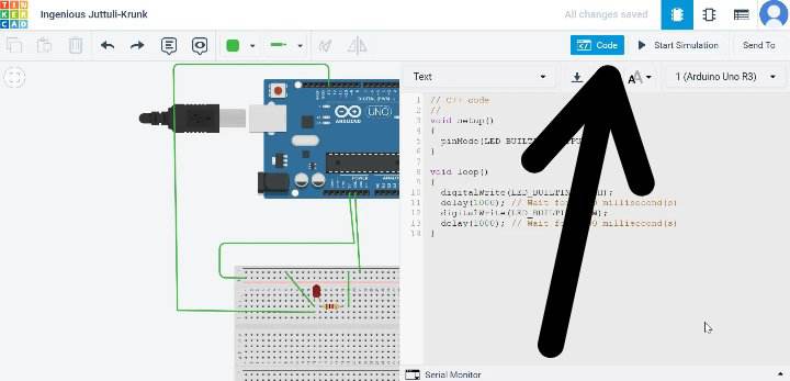
you will get a block and a text coding, go for text coding as shown below.
this week assignment is to use fabISP to program the echo hello board to do something intresting. Things i have learned from this week assignments are the basic workflow on how the coding works with the controllers. to undeerstand this; its important to know the datasheet of the the controller that we will programe. With the help of datasheet we can choose the right IC for our project.
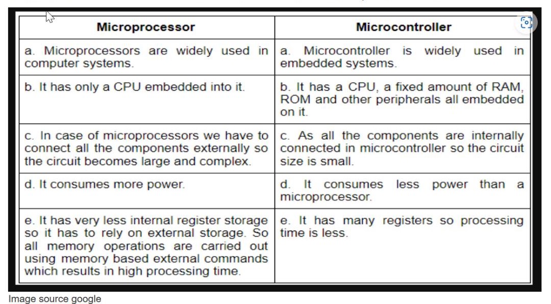
Microcontrtoller
A microcontroller is a VLSI(Very Large Scale Integration) Integrated Circuit(IC) that contains electronic CPU(computing unit and logic unit0, memory, Input/output port and few other components integrated on a single chip
Differences between Micro- controller and Micro processor
Reading Data Sheet
According to wikipedia A datasheet, data sheet, or spec sheet is a document that summarizes the performance and other characteristics of a product, machine, component (e.g., an electronic component), material, subsystem (e.g., a power supply), or software in sufficient detail that allows a buyer to understand what the product is and a design engineer to understand the role of the component in the overall system. Typically, a datasheet is created by the manufacturer and begins with an introductory page describing the rest of the document, followed by listings of specific characteristics, with further information on the connectivity of the devices. In cases where there is relevant source code to include, it is usually attached near the end of the document or separated into another file. Datasheets are created, stored, and distributed via product information management or product data management systems. Depending on the specific purpose, a datasheet may offer an average value, a typical value, a typical range, engineering tolerances, or a nominal value. The type and source of data are usually stated on the datasheet.
I have referred Esp32 Data sheet from google and you can get more information from
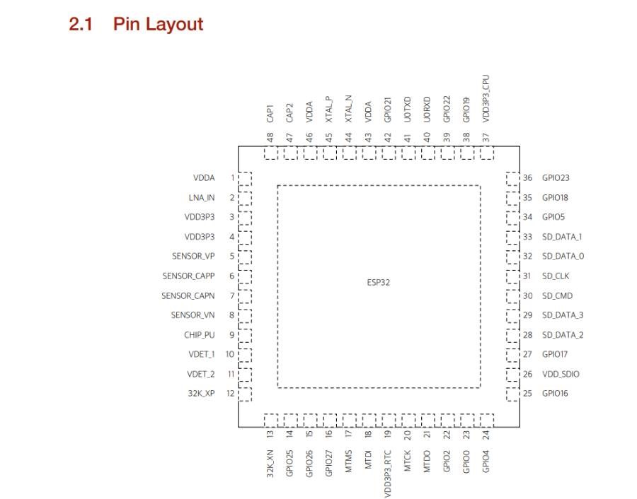
hereEsp 32 Pinout Diagram
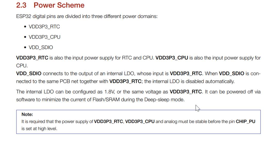
Pin configuration
Pin configuration will let us know pin responsibilities and IC connection. But we cannot use this pin address to program using arduino IDE. Different IDE have different pin adress for programming.
Pin out description
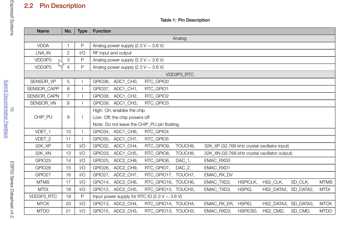
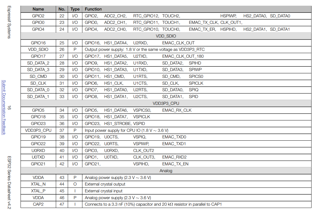
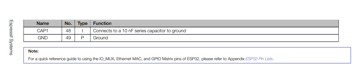
Here is the pin layout similar to pin Diagram.
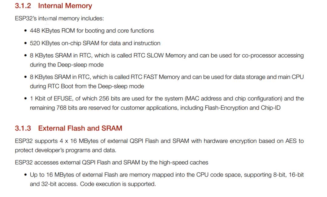
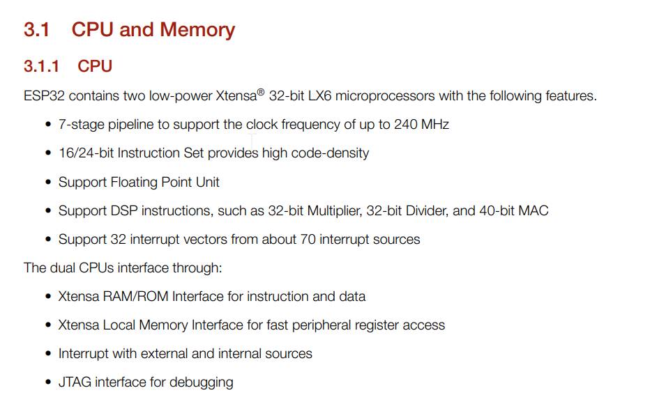
Esp32 Features
arduino uno birthday project.
Setting up arduino Ide
first download arduino Ide in your desktop and open it after installing it.
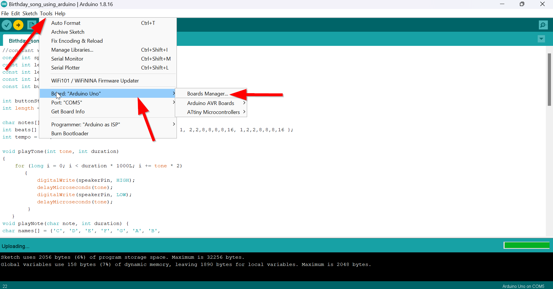
After that go to tool and select Board and select"arduino uno"
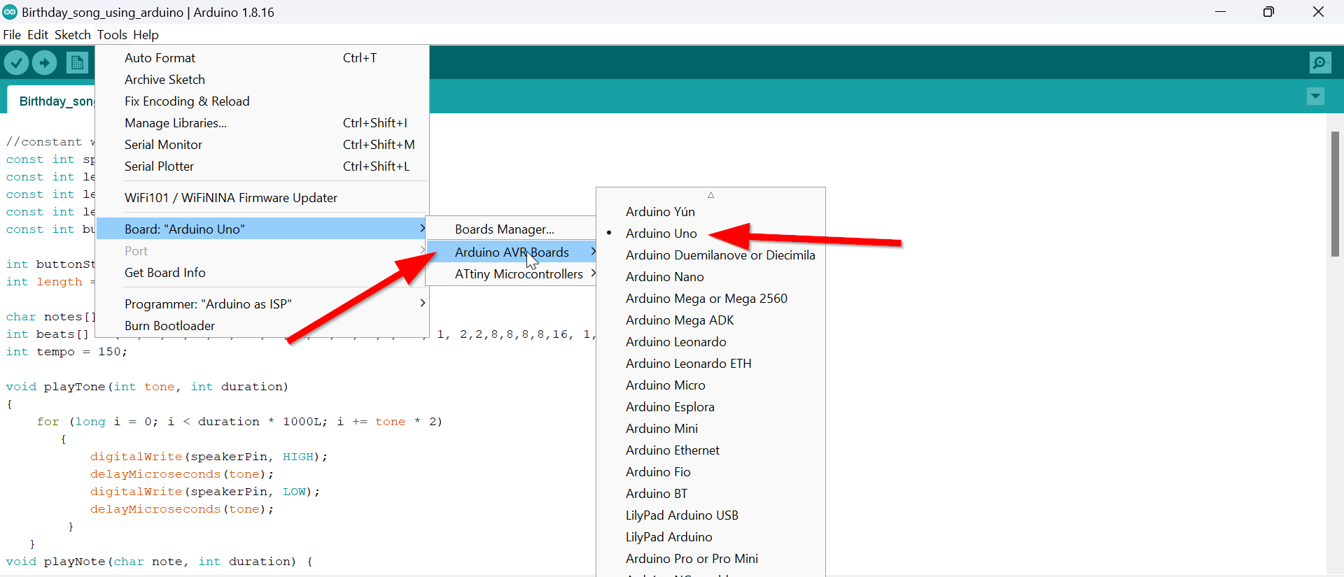
Next select arduino AVR Boards and you will get a drop down
Now select arduino Uno since you are going to use arduino uno right now.
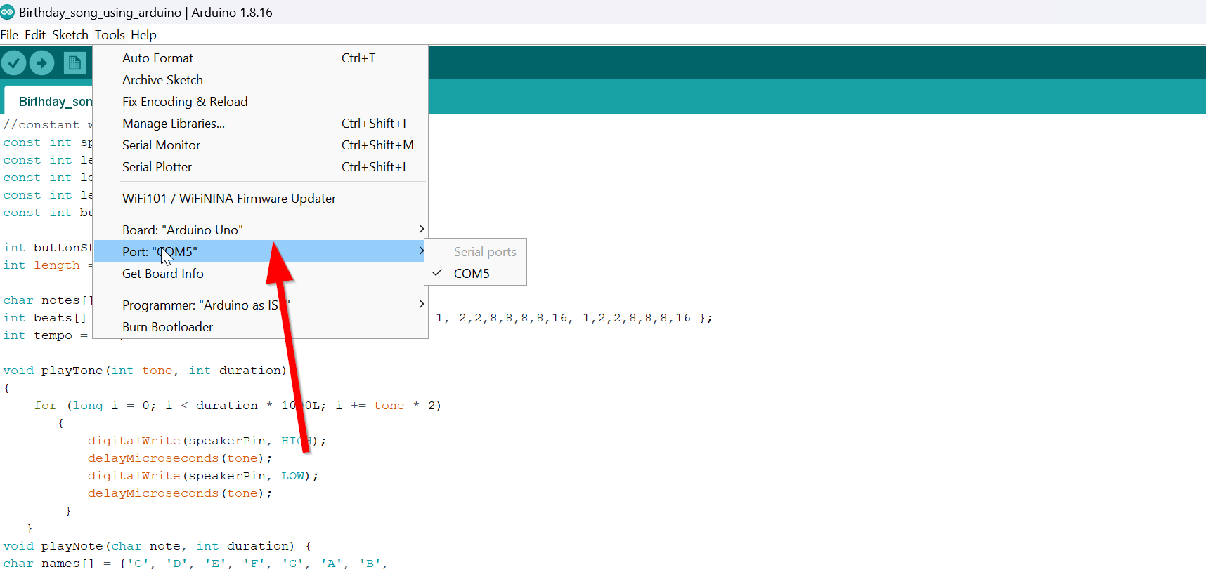
Now time to select port in order to connect the arduino board and your computer connected
Go to tools and select port Com; select what ever the Port com comes after connecting the ardunio.
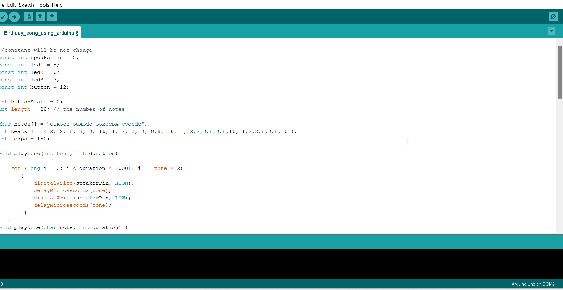
Mine is arduino uno + Led+ Buzzer+ Push button.(Birthday project)
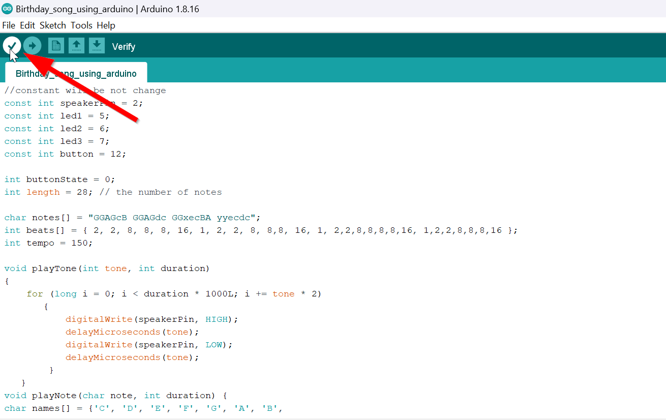
Tick sign
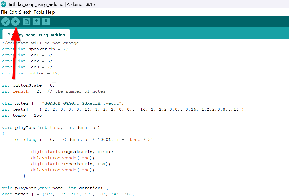
And select done compiling.
Now here is my video of success. after changing the code the sounds seems right and even the coding was right.
Connection source from google is here.
Circuit connection through Tinkercad.
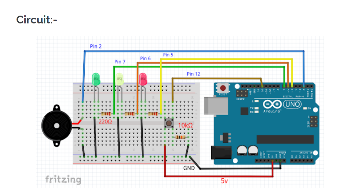
1. The buzzer having 2 pin, negative and positive.
2. Connect a jumper wire from positive pin of buzzer to Arduino pin 2.
3. Then connect a jumper wire from negative pin of buzzer to Arduino GND pin.
4. Attach a 220 ohms resistor to the positive pin (anode) of all LEDs and at the end of the resistor is connected to Arduino digital pin 5, 6 and 7 respectively.
 Picture source google.
5. Connecting Button pin 4 to Arduino pin 5v using a jumper wire.
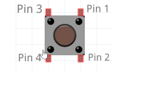
6. Attach a 10k ohms resistor to button pin 2 and at the end of the resistor is connected to Arduino pin GND.
7. Button pin 1 is connected to Arduino digital pin 4 using a jumper wire.
8. Now the circuit is readyyy…
Here is the youtube tutorial that help me a lot.(Code source google.)
connection source & code source from google.