Week 9. Output Devices
Group Assignment
Our group assignment link.
Individual Assignment
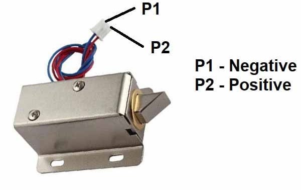
This week we need to add output device in our micro controller PCB board that we have design last week. so in my case i have re-design the PCB board for my output device. I was thinking to use 12V Solenoid Lock as a output device, as in my final project i want to use this in my smart door lock.
PCB Design
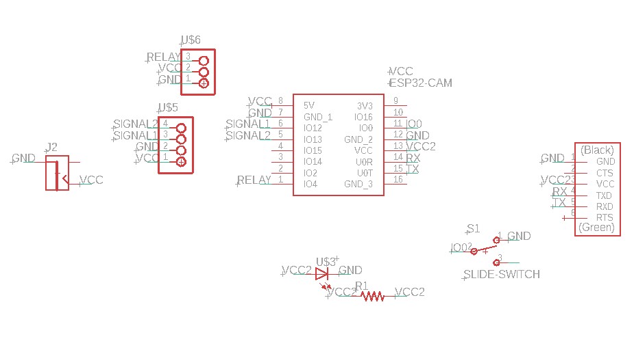
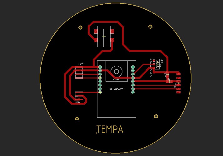
Here i have exported the outline and traces of my board in png format.
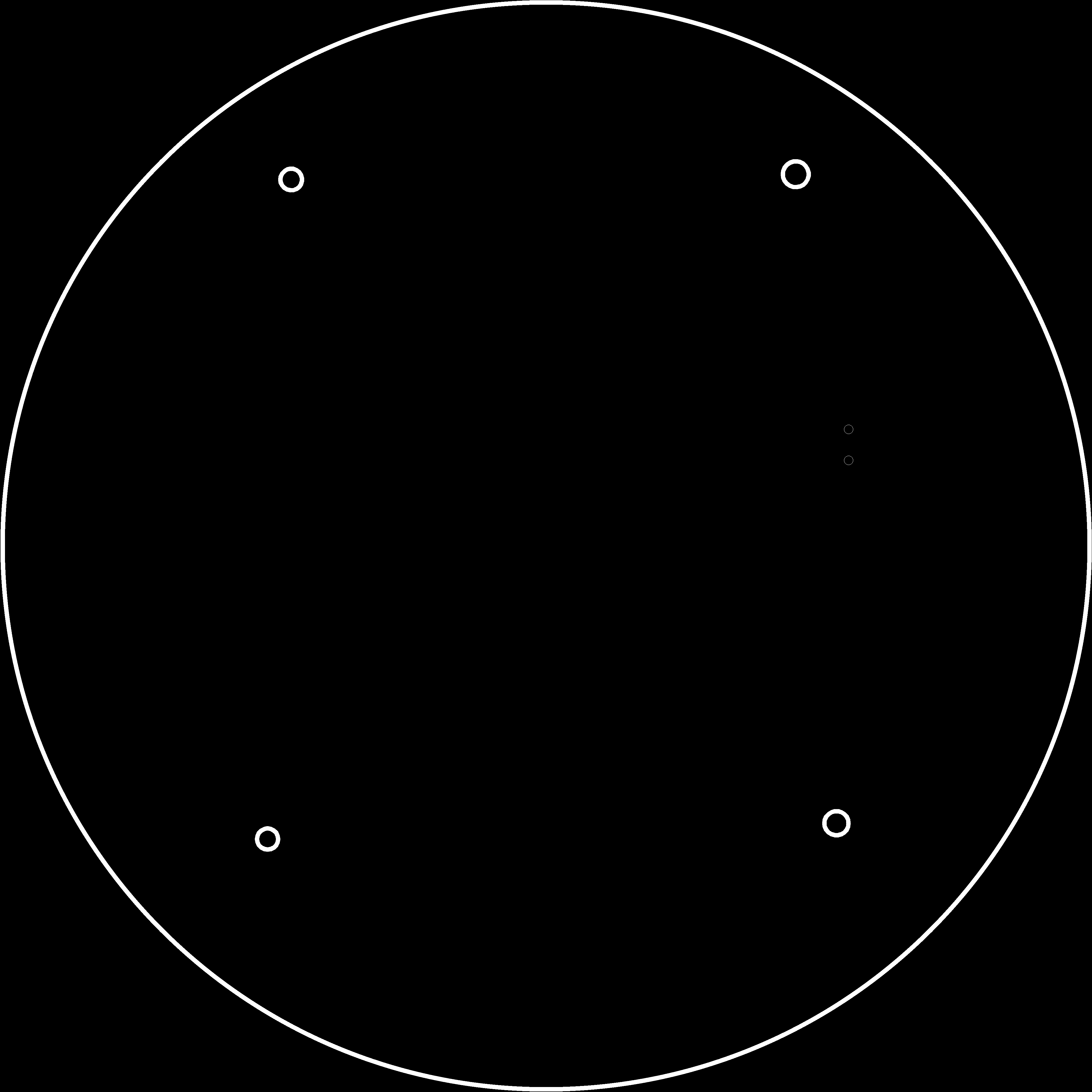
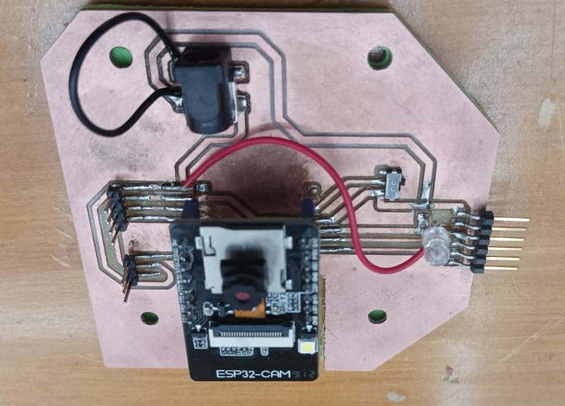
My final board
Programming the board.
Solenoid lock as Output with Esp32-CAM Board
Components Required
The connections I made with ESP32-CAM are
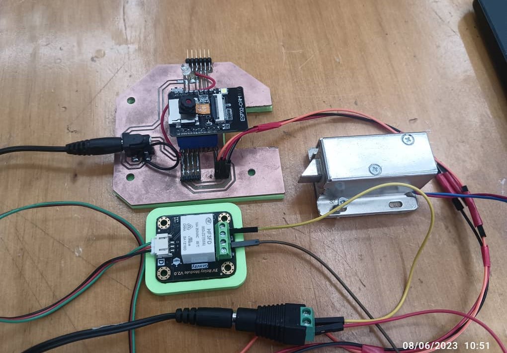
The connection I made with my board and Solenoid lock
After the connections were made, then started coding:
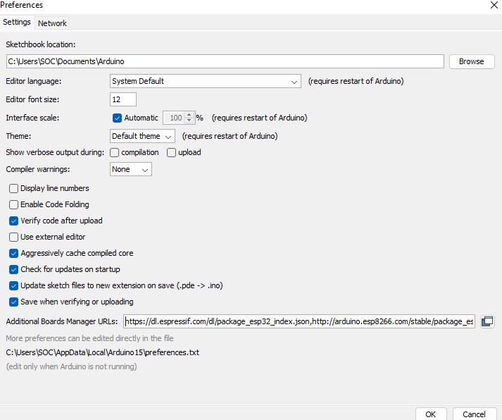
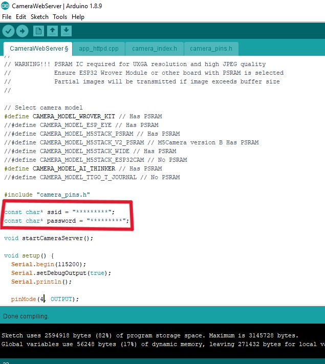
Before uploading the code to ESP32-CAM, please check the following setting that i have done here:
https://dl.espressif.com/dl/package_esp32_index.json
Board Settings:
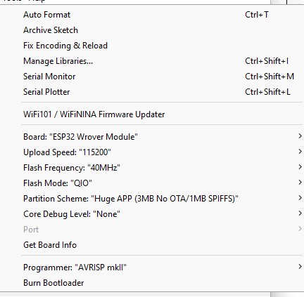
Don't forget to assign your Wifi SSID and Password here to access camera
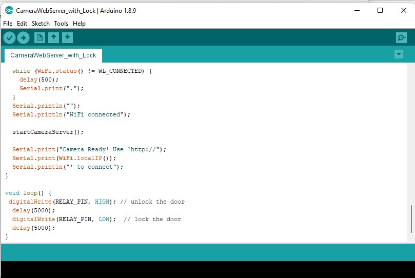
Here i have define relay pin and added the coding for Lock to function
After connecting GPIO 0 to GND pin, upload your code and press ESP32 CAM on-board RESET button to put the board in the flashing mode
After uploading the code disconnect the GPIO-0 pin from GND pin from your board.
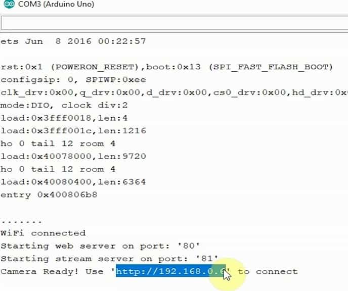
Then Open Serial Monitor
Set the Baud rate to 115200
Press the ESP32 CAM on-board RESET button to get IP address and Lock to function.