Week 8 - Electronics Production
Group Assignment:
Here is our group assignment Link for this week.
Individual Assignment
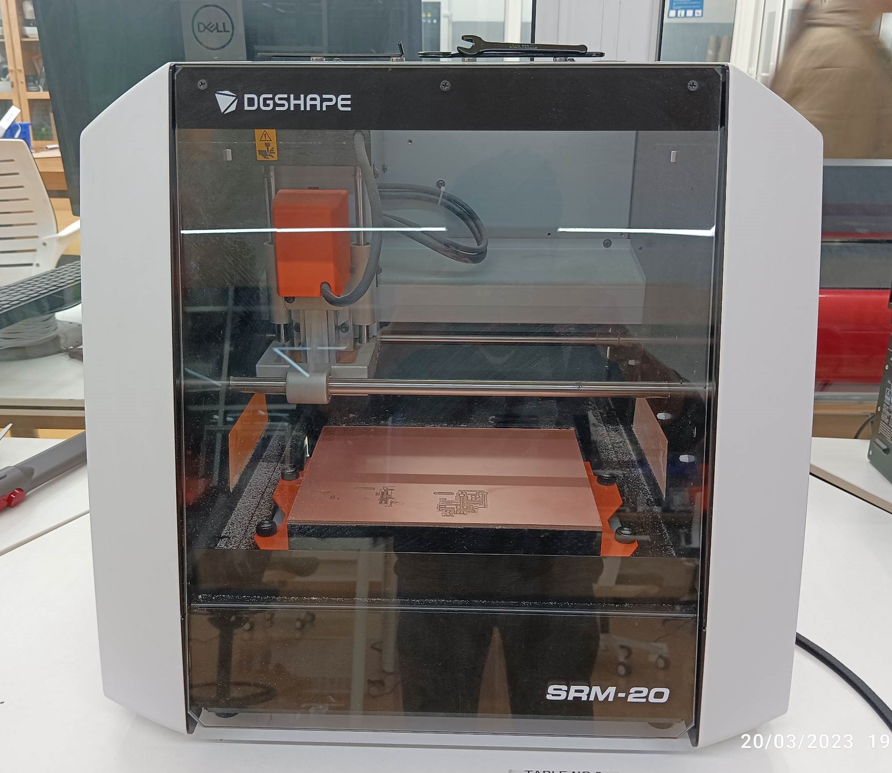
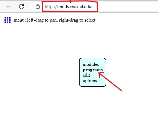
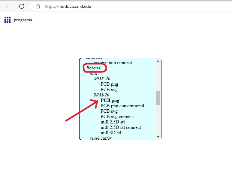
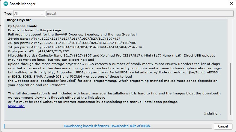
In this week, we have to characterize the specification of PCB (Printed Circuit Board) production processes and have to learn about milling machines. In our lab, we have a Roland SRM-20 machine and this machine reads an rml file. For this we need to go to Mods,which changes png format into rml.
The machine: Roland SRM 20
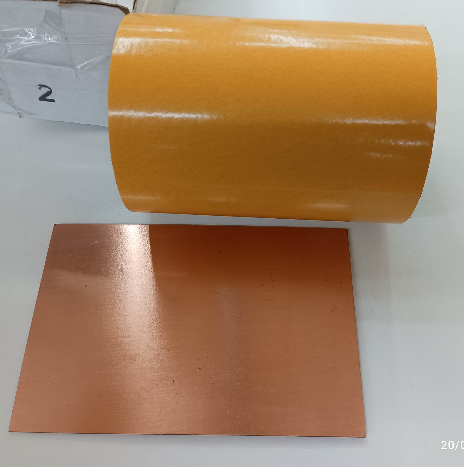
Materials required:

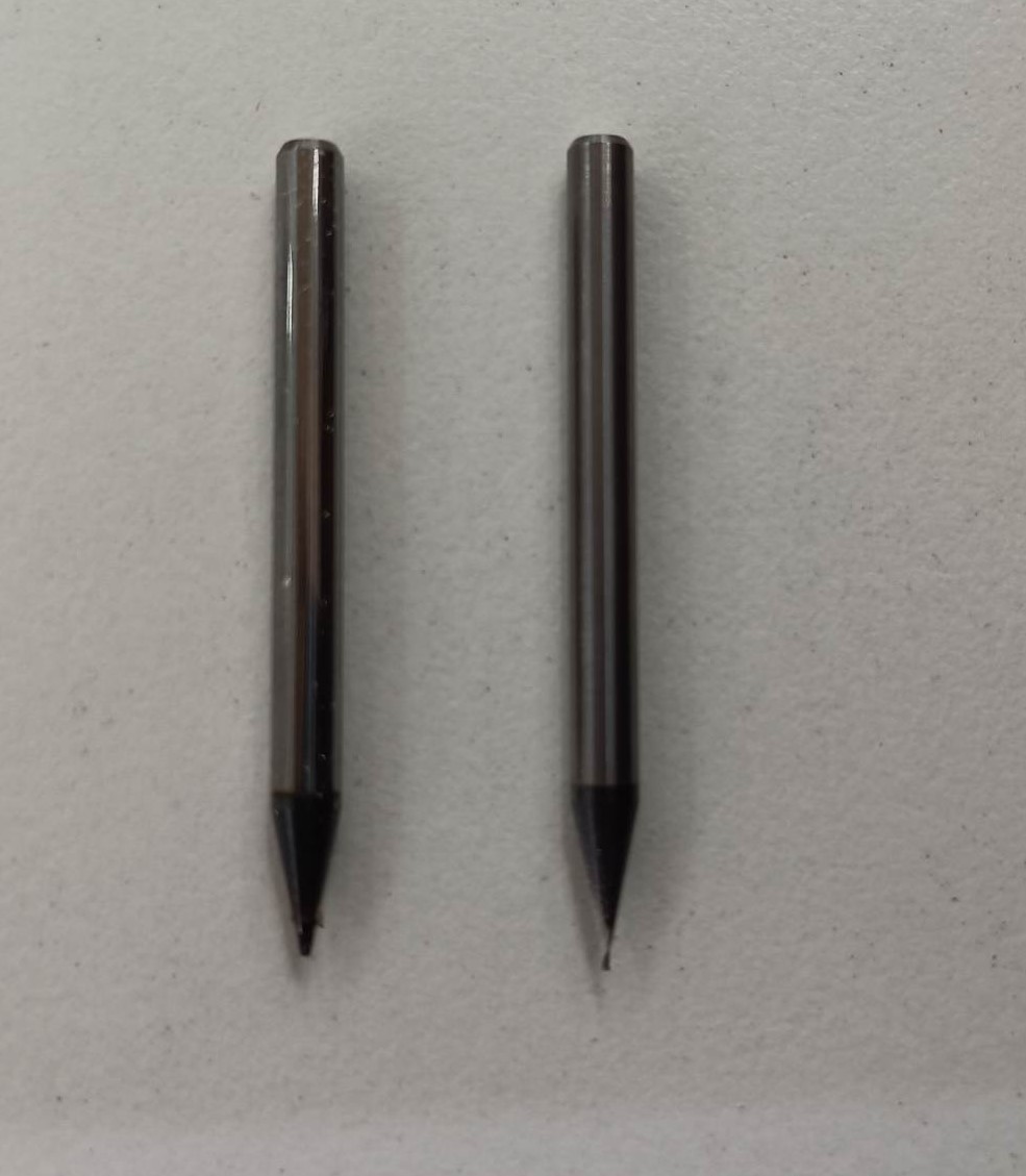
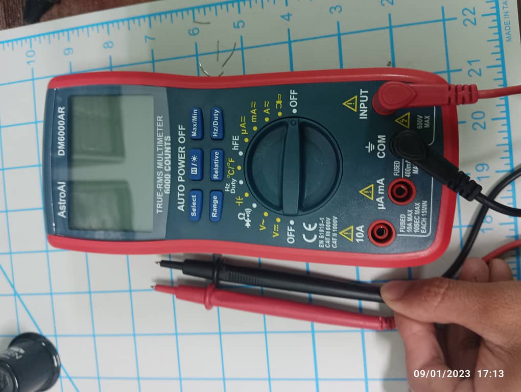
Tools
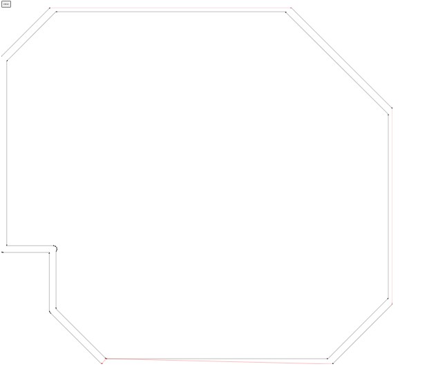
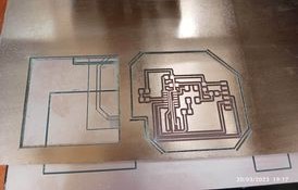
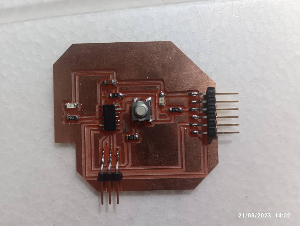
PCB PCB MILLING BY SRM-20.
For milling my PCB board I have used Roland SRM 20 machine.
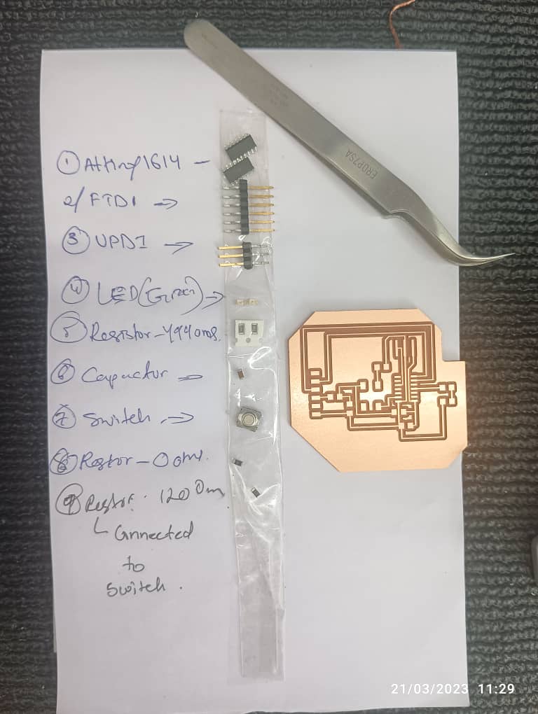
Components I used to design my board.
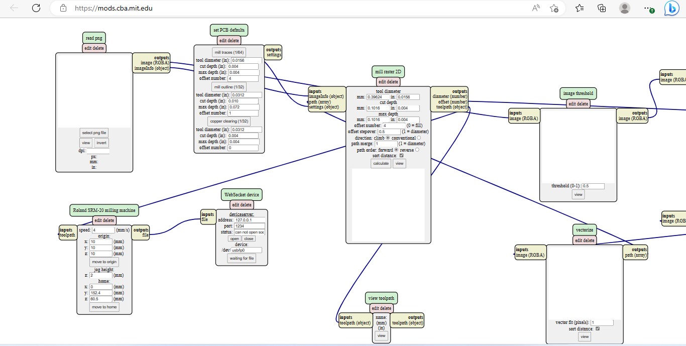
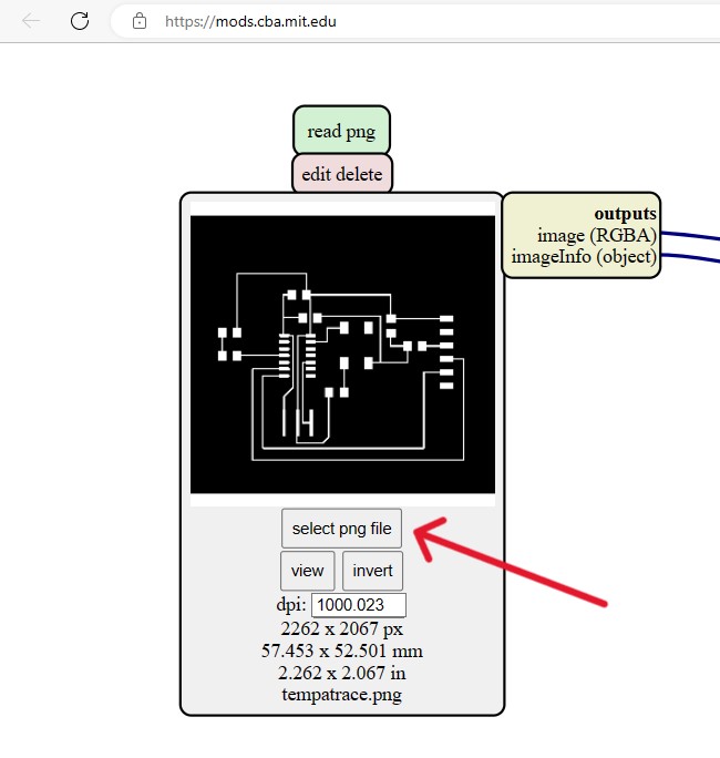
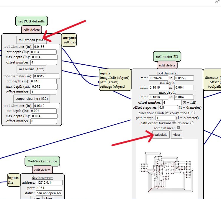
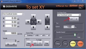
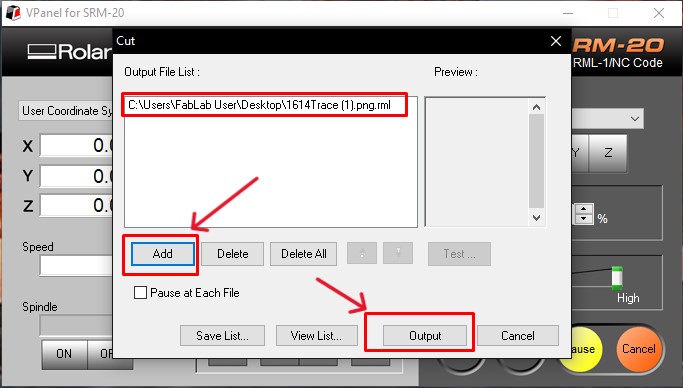
Workflow for MODS:

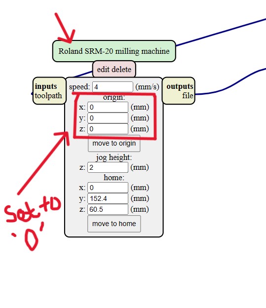
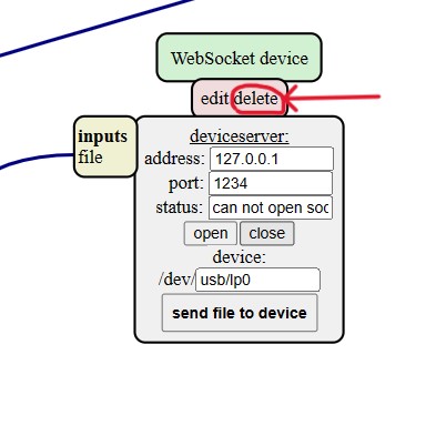
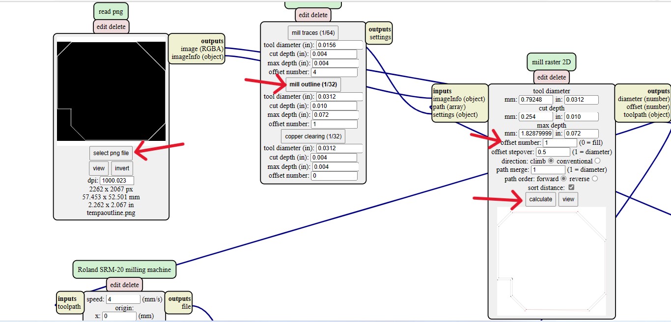
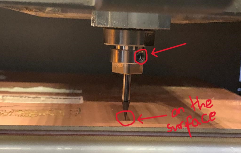
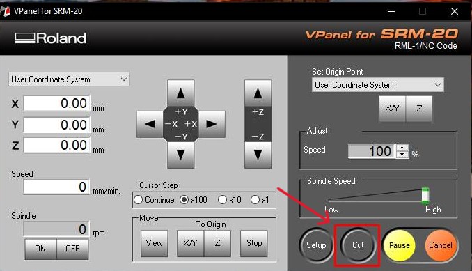
Using SRM20
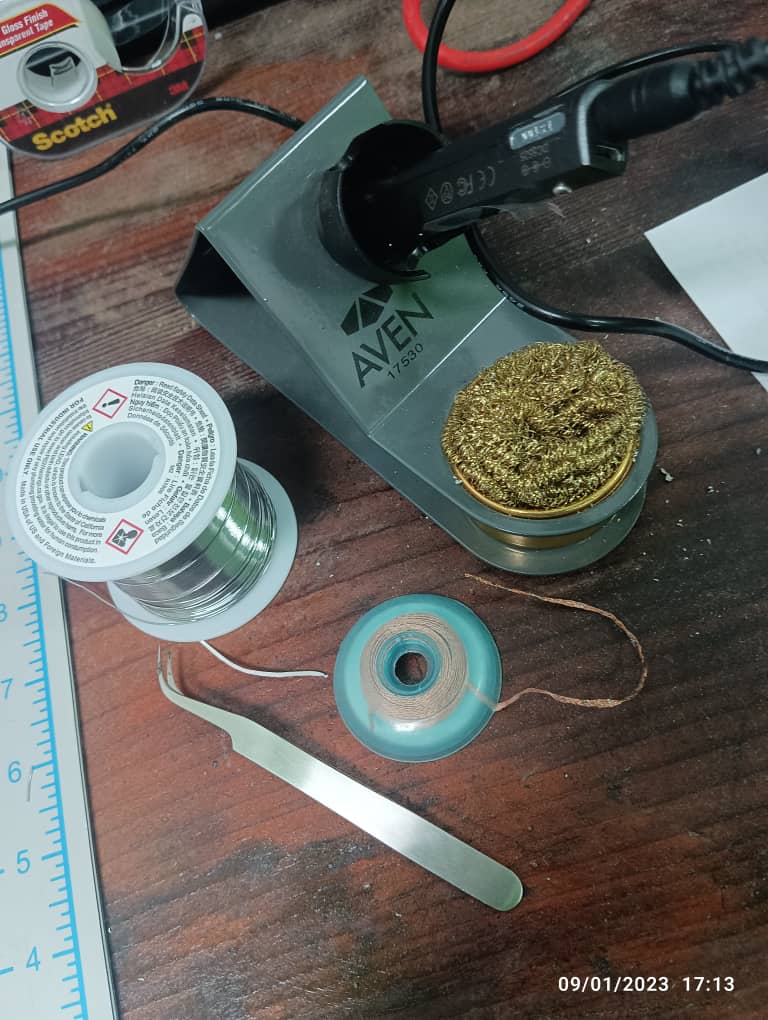
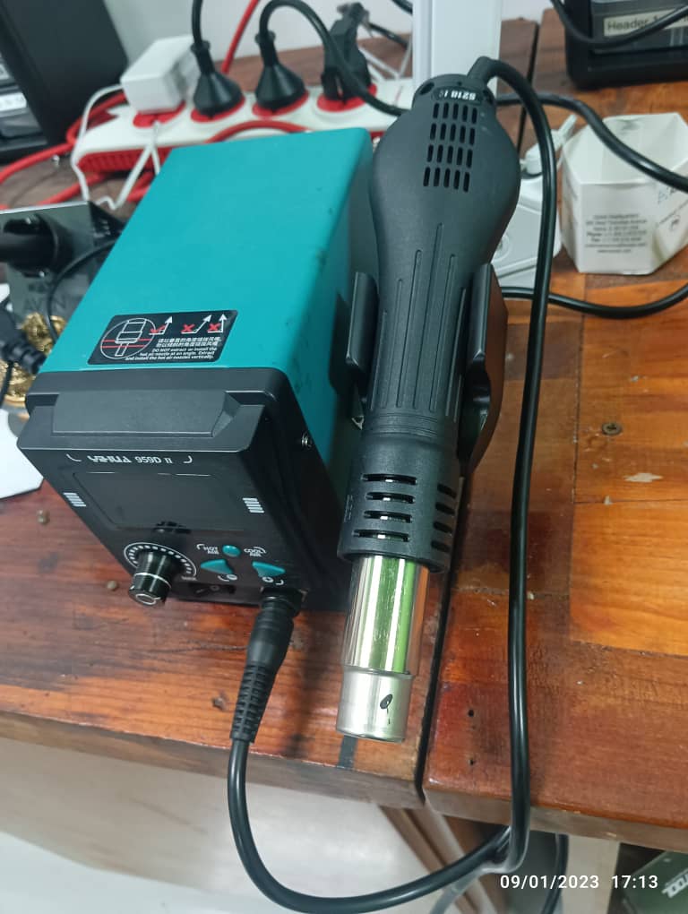
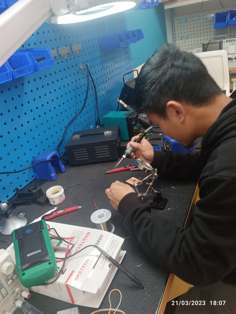
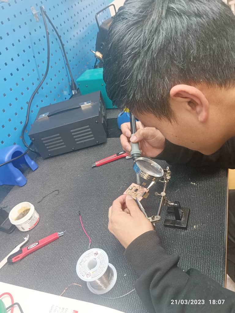
Soldering my PCB.
Soldering is a joining process used to join different types of metals together by melting solder. Solder is a metal alloy usually made of tin and lead which is melted using a hot iron. The iron is heated to temperatures above 600 degrees fahrenheit which then cools to create a strong electrical bond.
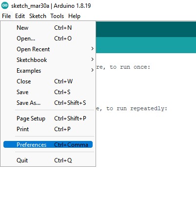
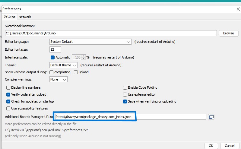
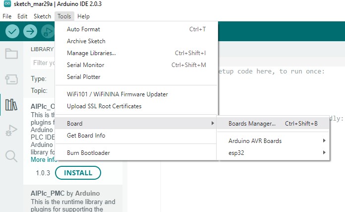
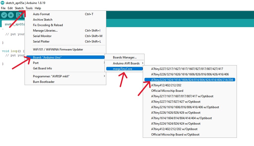
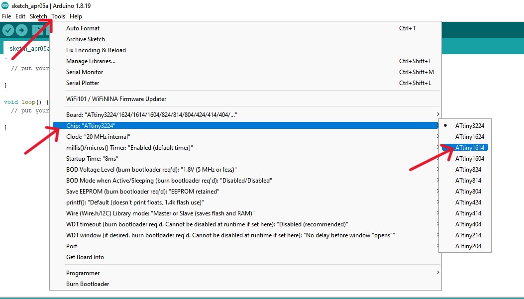
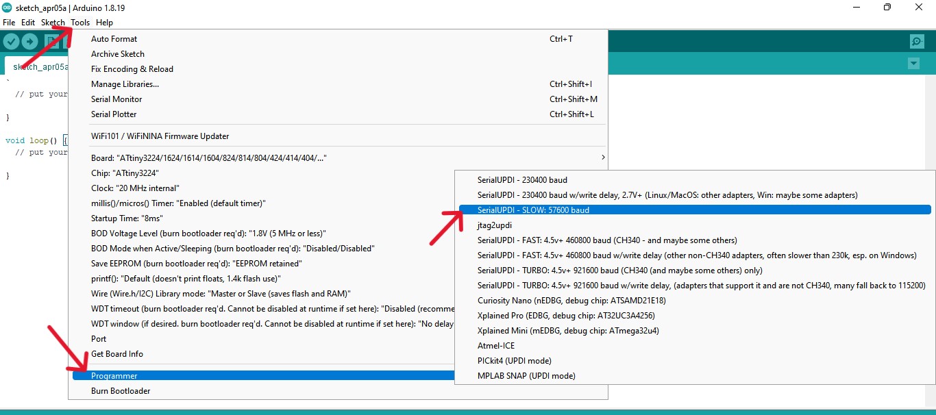
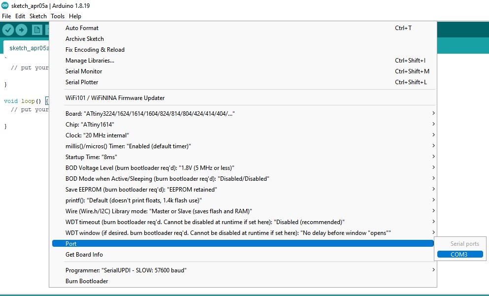
Programming the board
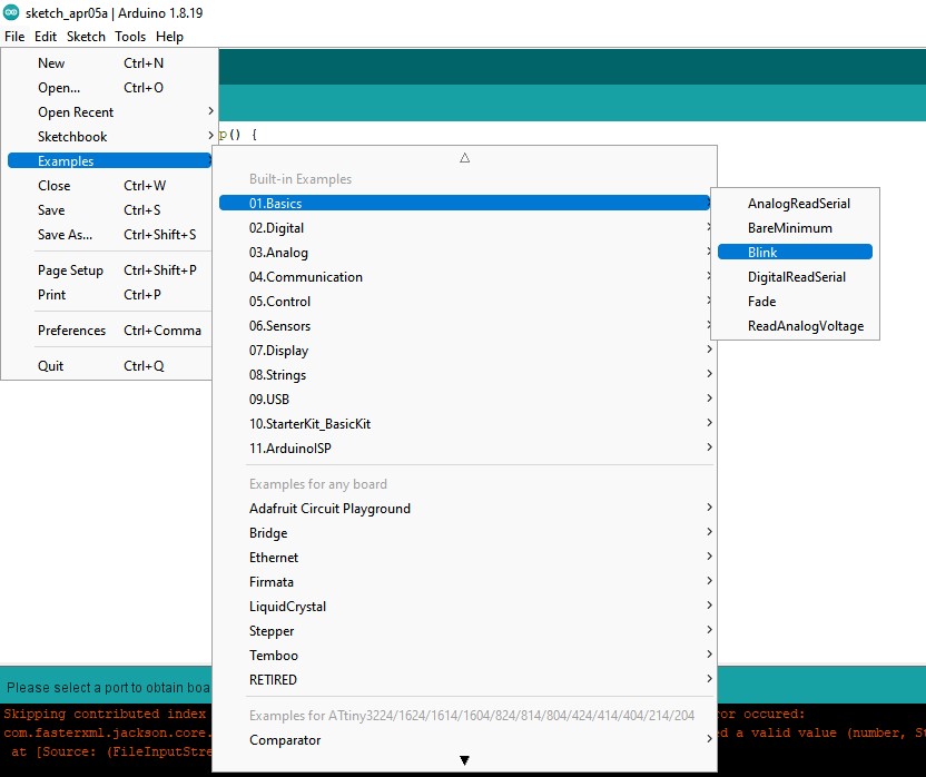
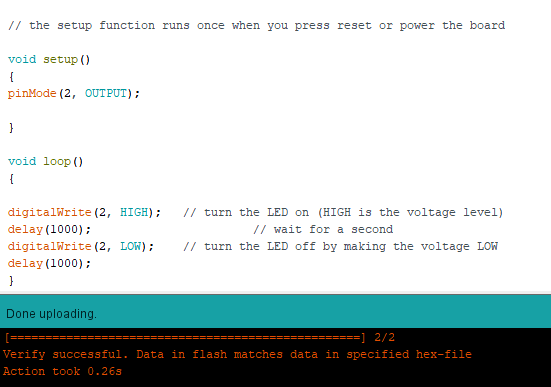
LED blink test
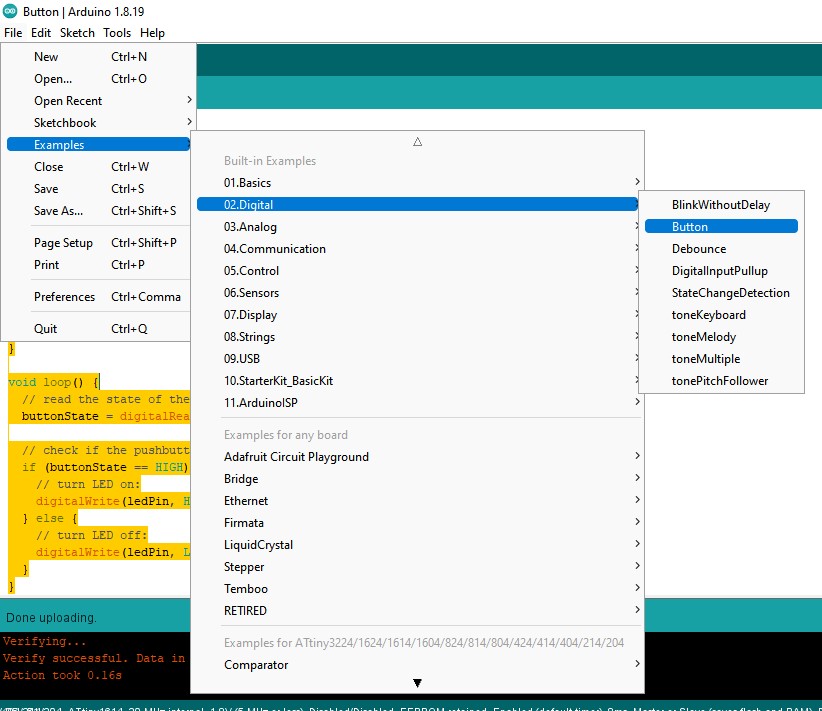
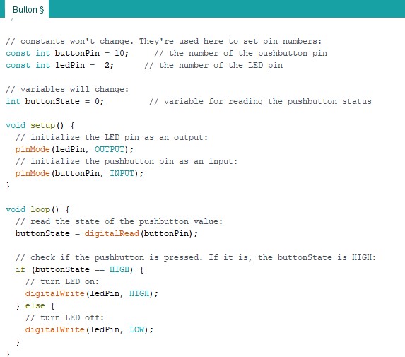
Programming the pushbutton
Electronics FAQs:
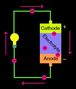
Q. What's a circuit?
A circuit is a closed loop that electrons can travel in. Such as a battery, provides electrical energy in the circuit.
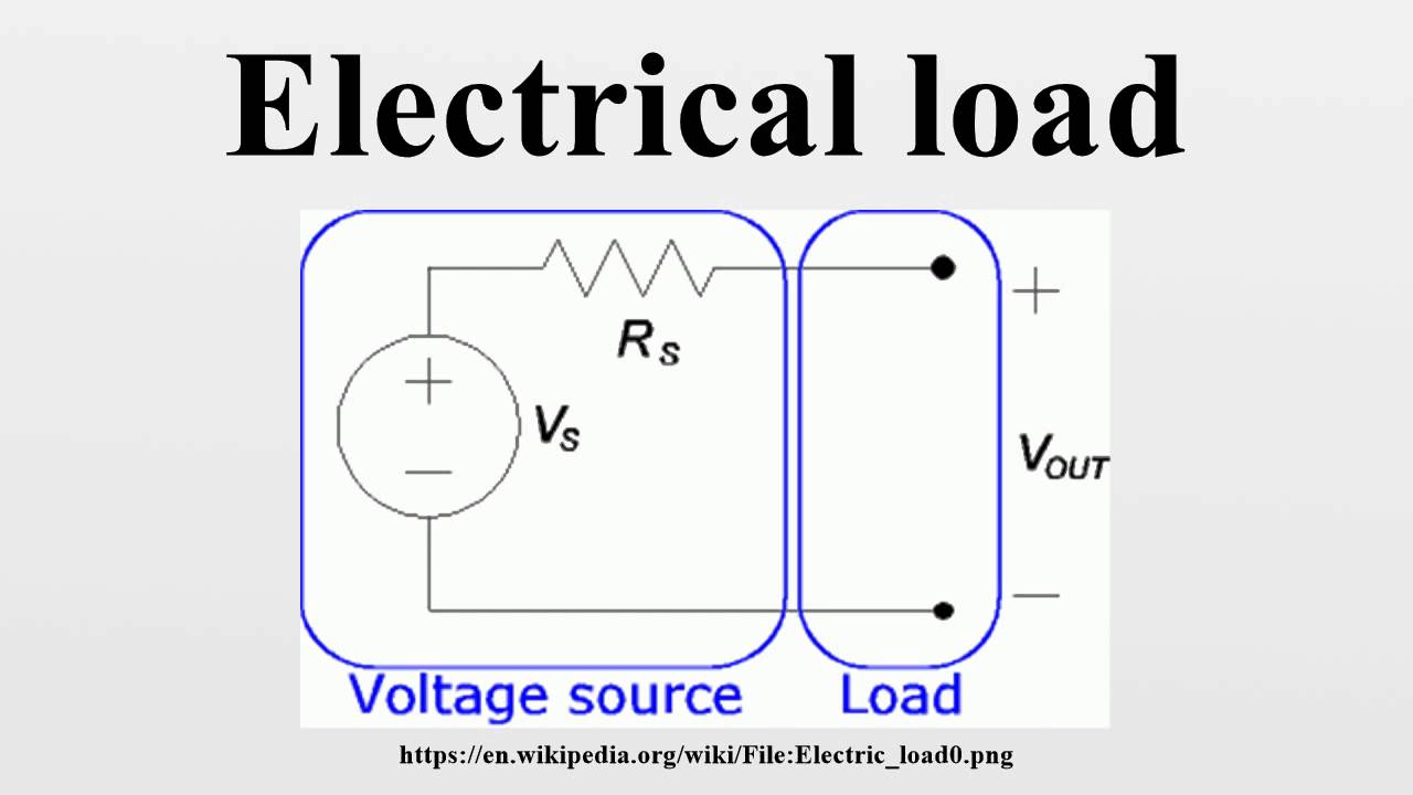
Q. What is a load?
An electrical load is the component of the circuit that consumes energy or power. Which includes light bulbs and appliances.
Q. What is a conductor?
A conductor is a substance or material that allows electricity to flow through it.
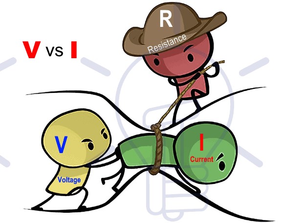
Q. What is the difference between Voltage, Current and Resistance?
Voltage is the difference in charge between two points. Current is the rate at which charge is flowing. Resistance is a material's tendency to resist the flow of charge (current).
Q. What is Ohm’s Law?
Ohm’s Law states that the current through a conductor between two points is directly proportional to the voltage across the two points. Which states V=IR (R is constant)
Q. What does a Resistor do?
Resistor is actually a electronic component which limits the flow of electric current in a circuit.
Q. What does a Capacitor do?
A capacitor stores energy temporarily and can discharge the energy very quickly. They have high power densities.
Q. What does a Diode do?
A diode is a semiconductor device that essentially acts as a one-way switch for current. It allows current to flow easily in one direction.
Q. What does LED mean?
LED stands for Light emitting diode and it is a semiconductor device that emits light when an electric current passes through it.
Q. What is a Regulator?
Regulator is a electronic device which stabilize the output voltage or current of a power supply to a specific level despite variation in input voltage or load current.
Q. What is a Bypass Capacitor?
It is a capacitor that is placed between DC and ground to remove any AC components of the signal.
Q. What is a Current Limiting Resistor for an LED do?
The current limiting resistor limits the current for the LED and regulates the difference in voltage drops between the LED and the power supply.
Q. How are Capacitors used as High-pass and Low-pass filters? What does it filter?
The capacitors act as high-pass filters when they pass high frequencies and block DC(Direct current). The capacitors act as low-pass filters when they pass DC signals and block AC signals.Instead of placing the capacitor in series with the component, the capacitor will be placed in parallel. It filters out AC signals.
Q. What is VCC?
Voltage Common collector is the power input of the device.
Q. What is GND?
GND stands for Ground and it refers to a common reference point in an electronic circuit that has zero volts potential.
Q. What is Common Ground?
It is a Electronic devices that don't plug into a wall socket have a different type of ground usually called common ground. A circuit that runs on batteries will often use the battery's negative terminal as common ground - a reference point of zero volts compared to the battery's positive terminal.
Q. What is a Ground Plane and why is it used?
A ground plane on a printed circuit board (PCB) is a large area or layer of copper foil connected to the circuit's ground point, usually one terminal of the power supply. It serves as the return path for current from many different components.