Week6- Electronics design
Group Project:
use the test equipment in your lab to observe the operation of a micro controller circuit board
- multimeter
- `power: P = I2R = IV`
logic analyzer : signals from input and output.
Oscilloscope: wave form of the electricity: analog vs digital.
During group assignment i have learned how to test resistance and voltage of any components from multimeter device and also learn how to find digital signal using oscilloscope machine.
Group assignment link
Individual Assignment
Design a development board to interact and communicate with an embedded micro controller
Extra credit: try another design workflow
Extra credit: make a case for it
Extra credit: simulate its operation
This week for Electronics design I have decided to use Eagle software for designing my board as Eagle is my first use and want to learn more on this.
To download Eagle software click here.
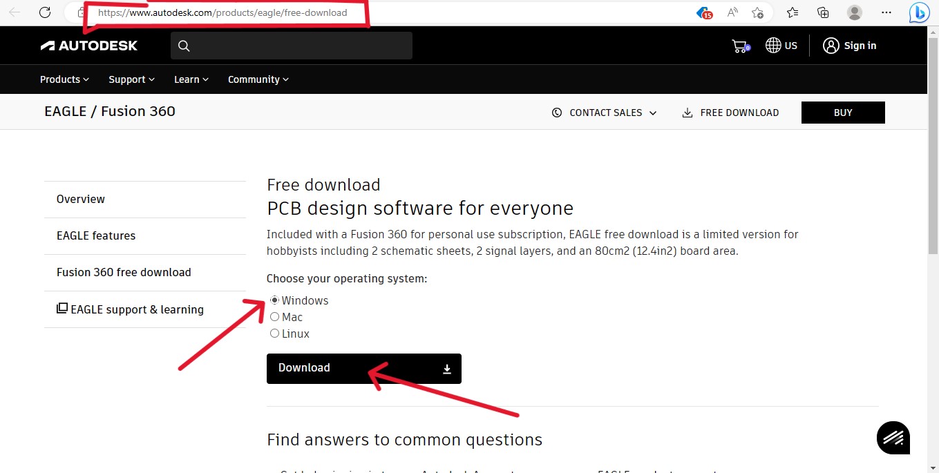
Eagle is a free software suite for electronic design automation. It facilitates the design and simulation of electronic hardware. It features an integrated environment for schematic capture, PCB layout, manufacturing file viewing, SPICE simulation, and engineering calculation.
To make a board i have used Attiny 1614 micro controller, with a following components:
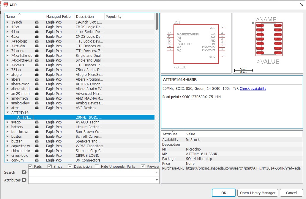
1. micro-controller ATTiny 1614
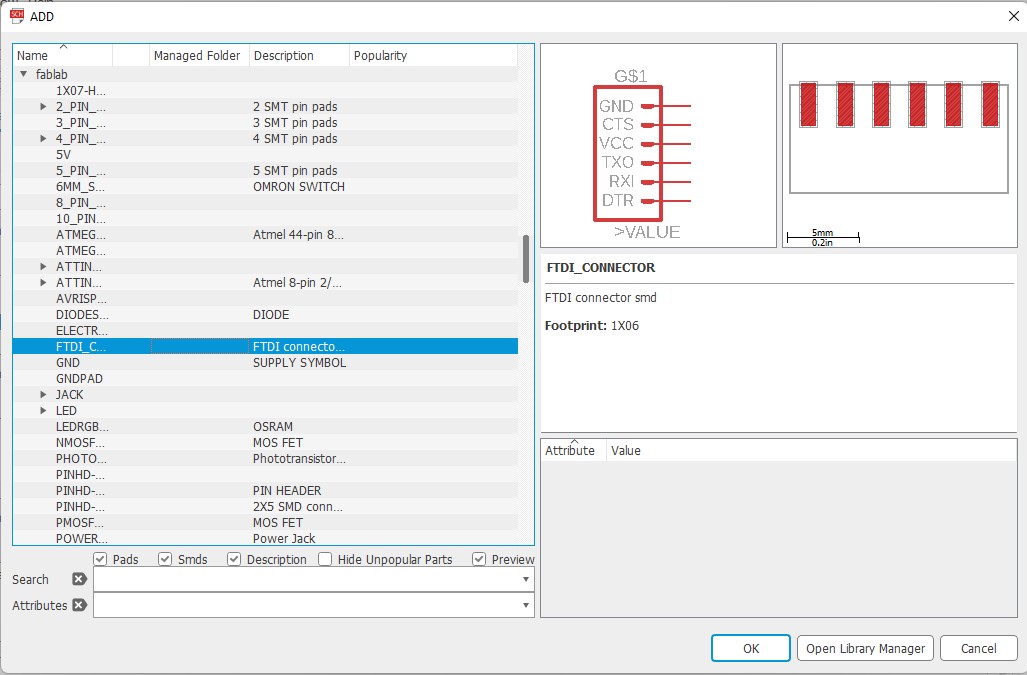
2. FTDI
3. UPDI
4. 2 LED
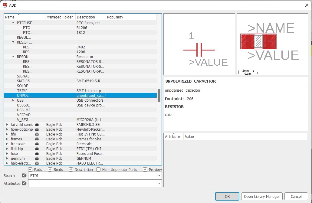
5. Resistor
6. Capacitor
7. Push button switch
Work Flow:
Firstly i have download the eagle software and installed in my window laptop.
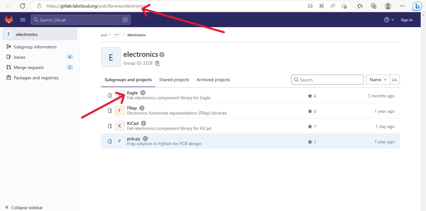
Then i have downloaded Fab library from this given link from gitlab.
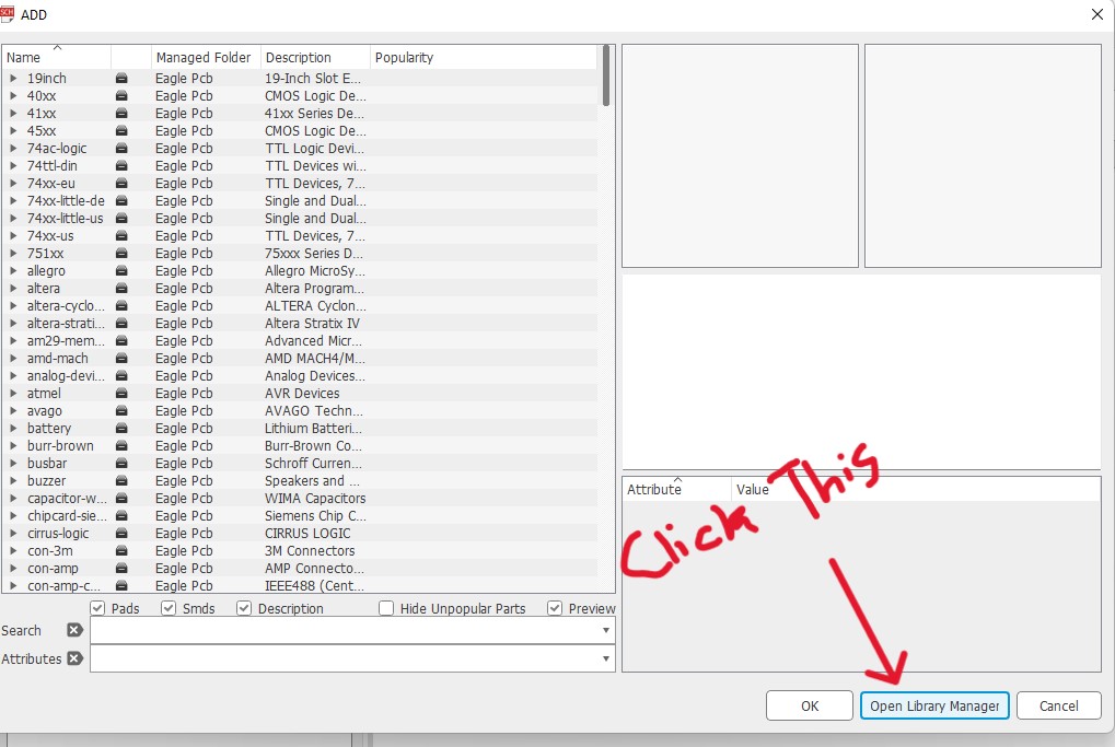
 After that open your Eagle software and add fab library in your eagle.
Go to Library → Open Library Manager → click on browse → select the fab library form where you have saved → click use.
After that open your Eagle software and add fab library in your eagle.
Go to Library → Open Library Manager → click on browse → select the fab library form where you have saved → click use.
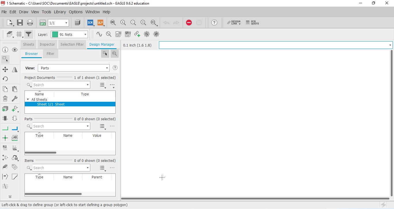
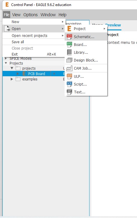
 Open your eagle software and create a new project to design your board and open in schematic editor.
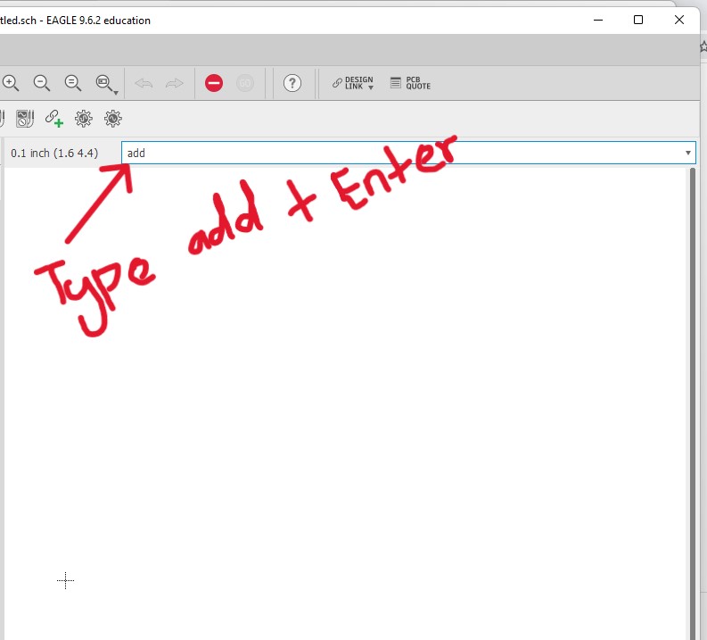
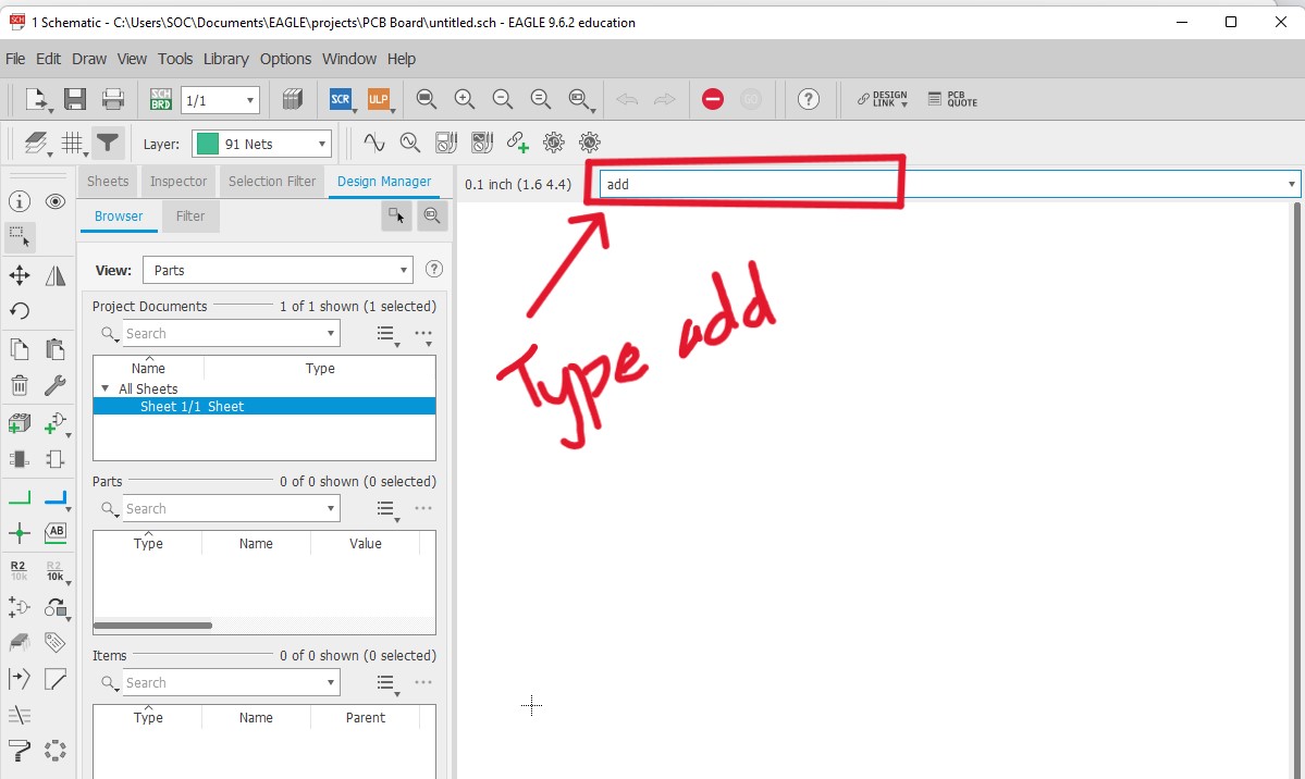
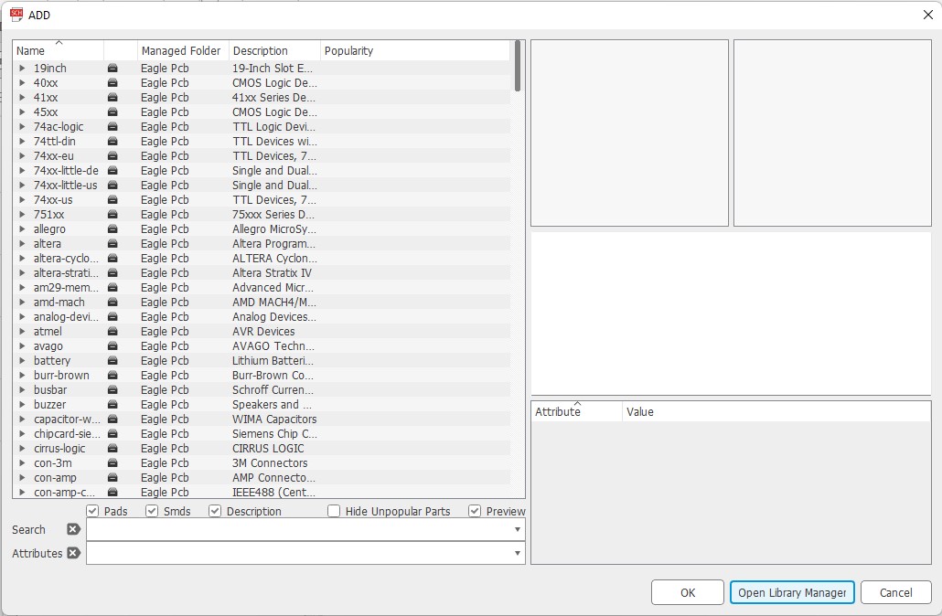
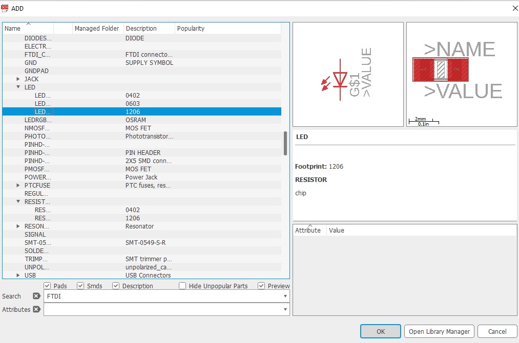
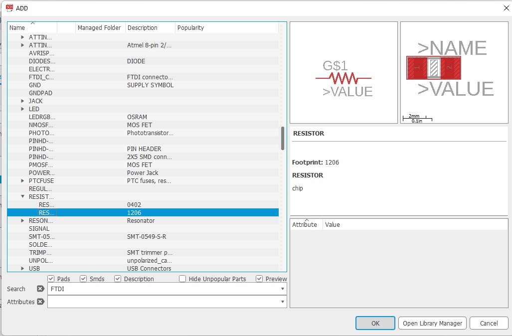
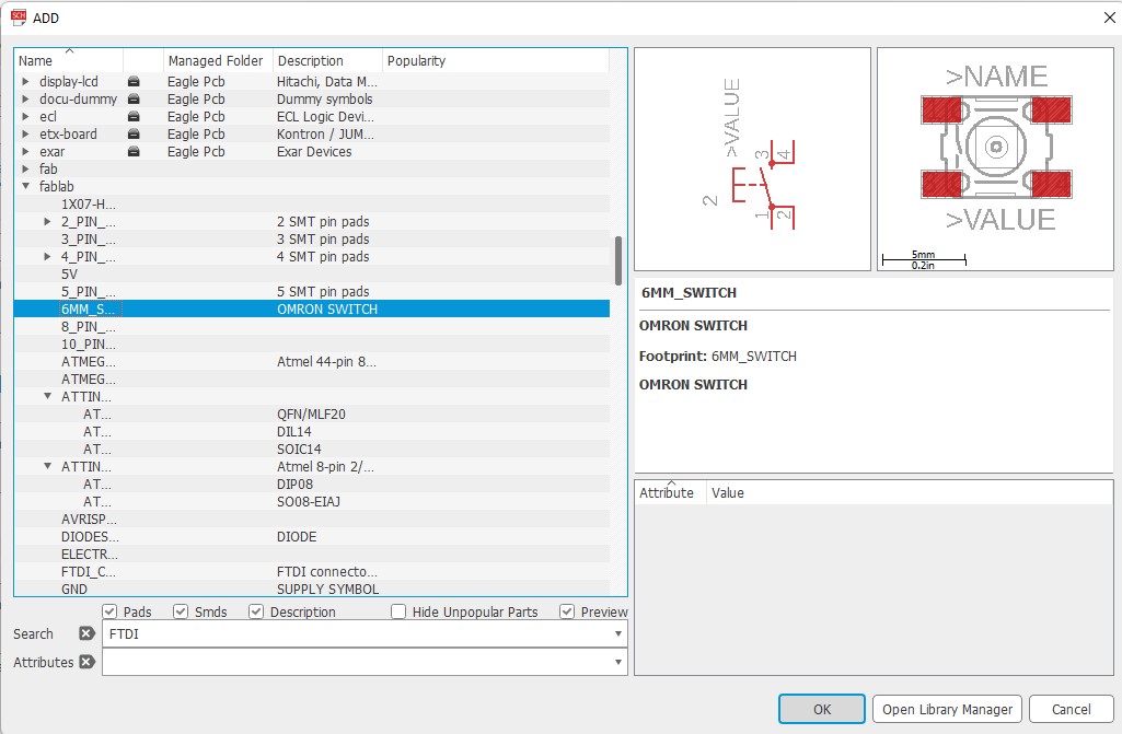
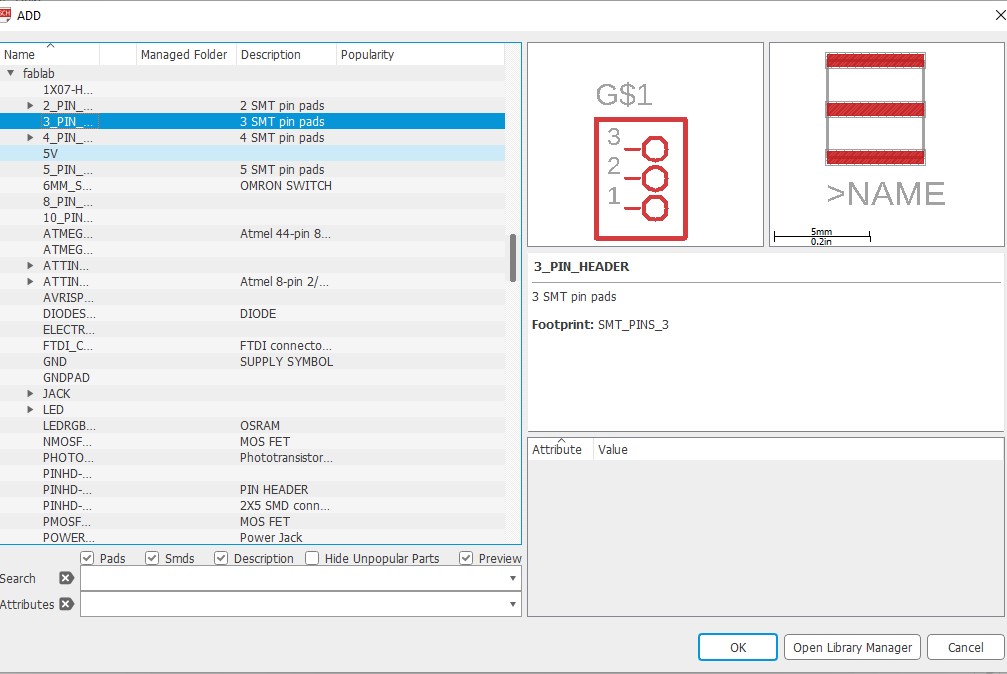
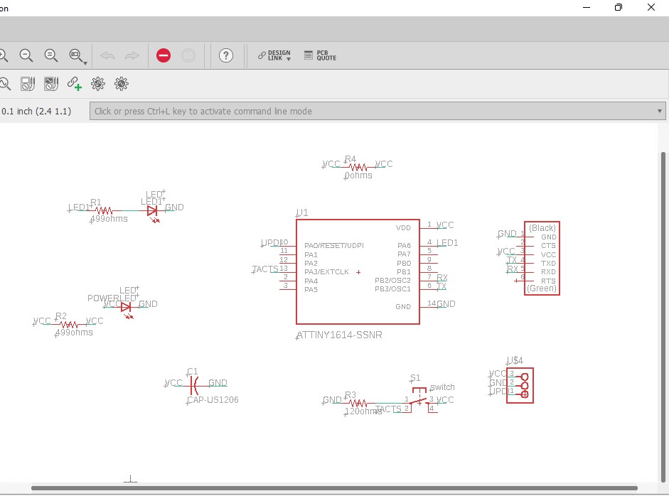
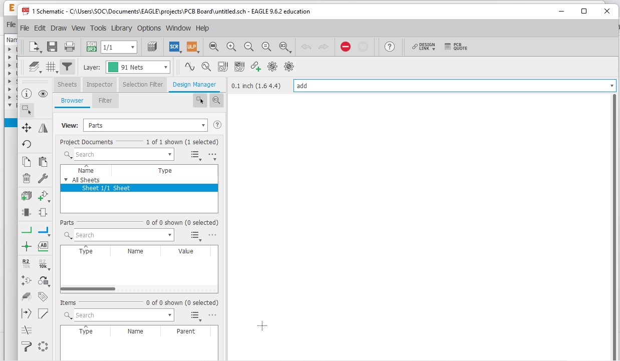 Now type add and enter to add components to your new Schematic. You can get all the components from the libraries that you have downloaded and installed earlier from git.
 Now i label the components here and labeling too. So for ATtiny 1614 i have download from this Link.
 components labelling
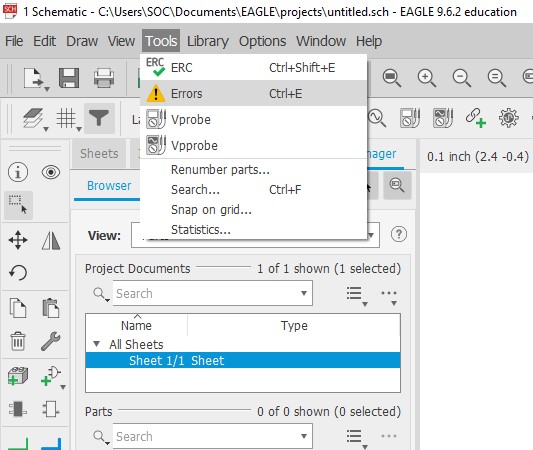
 After all the connections are done, Go to tools and click on ERC to check electrical rule check.
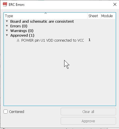
 After checking i have got a warning message for components with no value so i have ignore that and approve it all.
Updating Schematic to PCB Editor
Then I generated the board design from the schematic design as shown below.

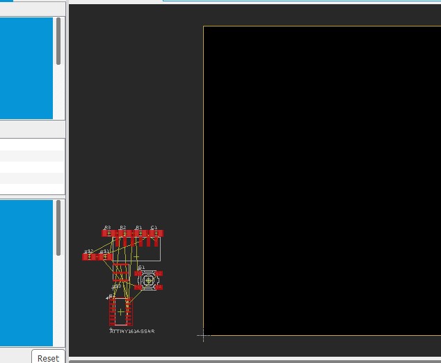 After I generated the board design, I stared arranging the components based on the best possible fit.
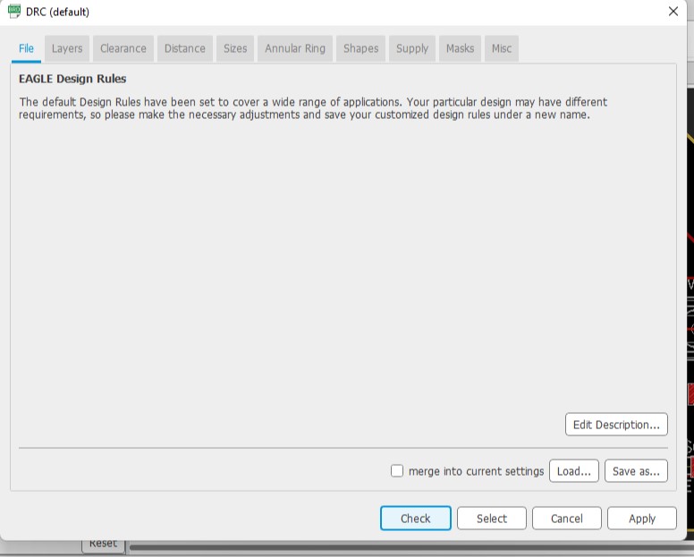
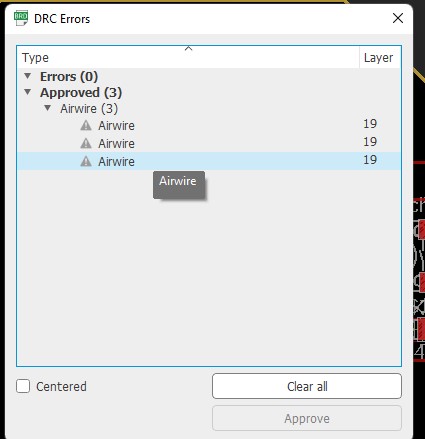
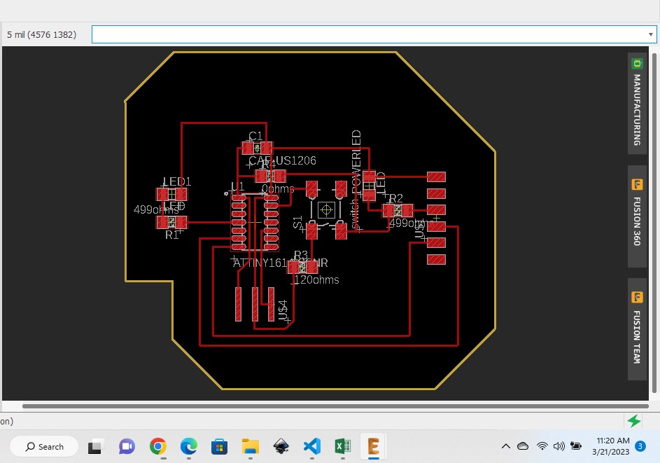 After that, run the DRC(Design Rule Check). So i got some errors with Airwires and so i have click on approved.
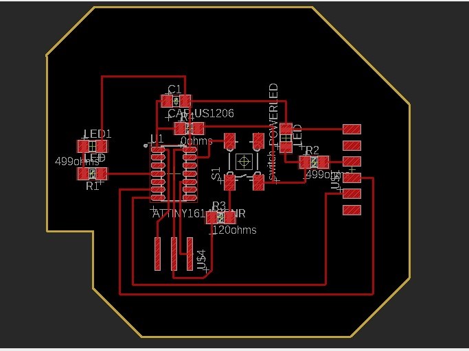
 Here is my final Board design in eagle.
Exporting and Saving your PCB Board.
before you save your PCb board, Firstly you need to removed the labeling on the components by going to view option and Select layer setting.
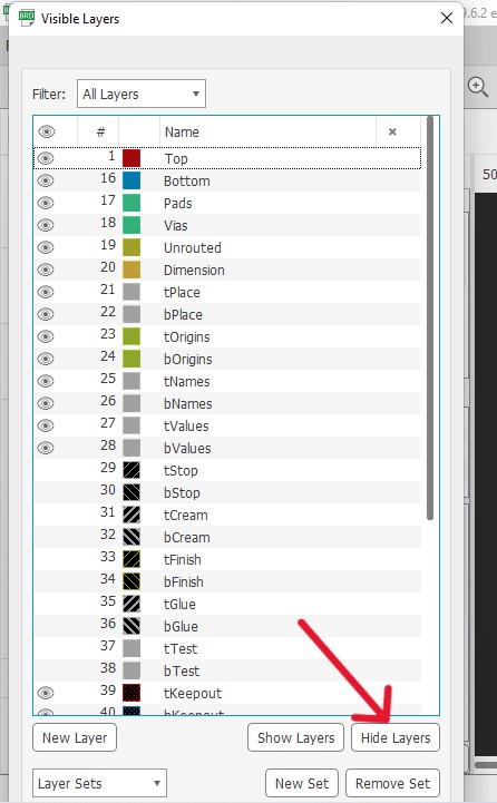
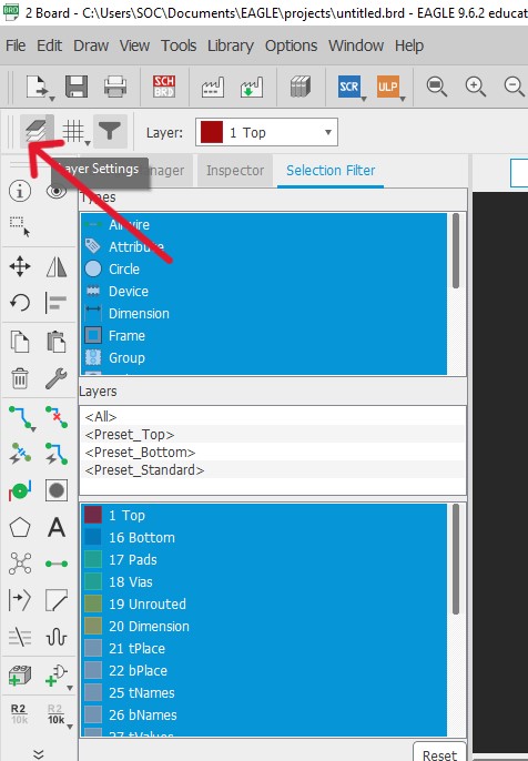 Click on hide all the layers.
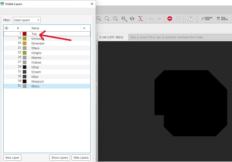
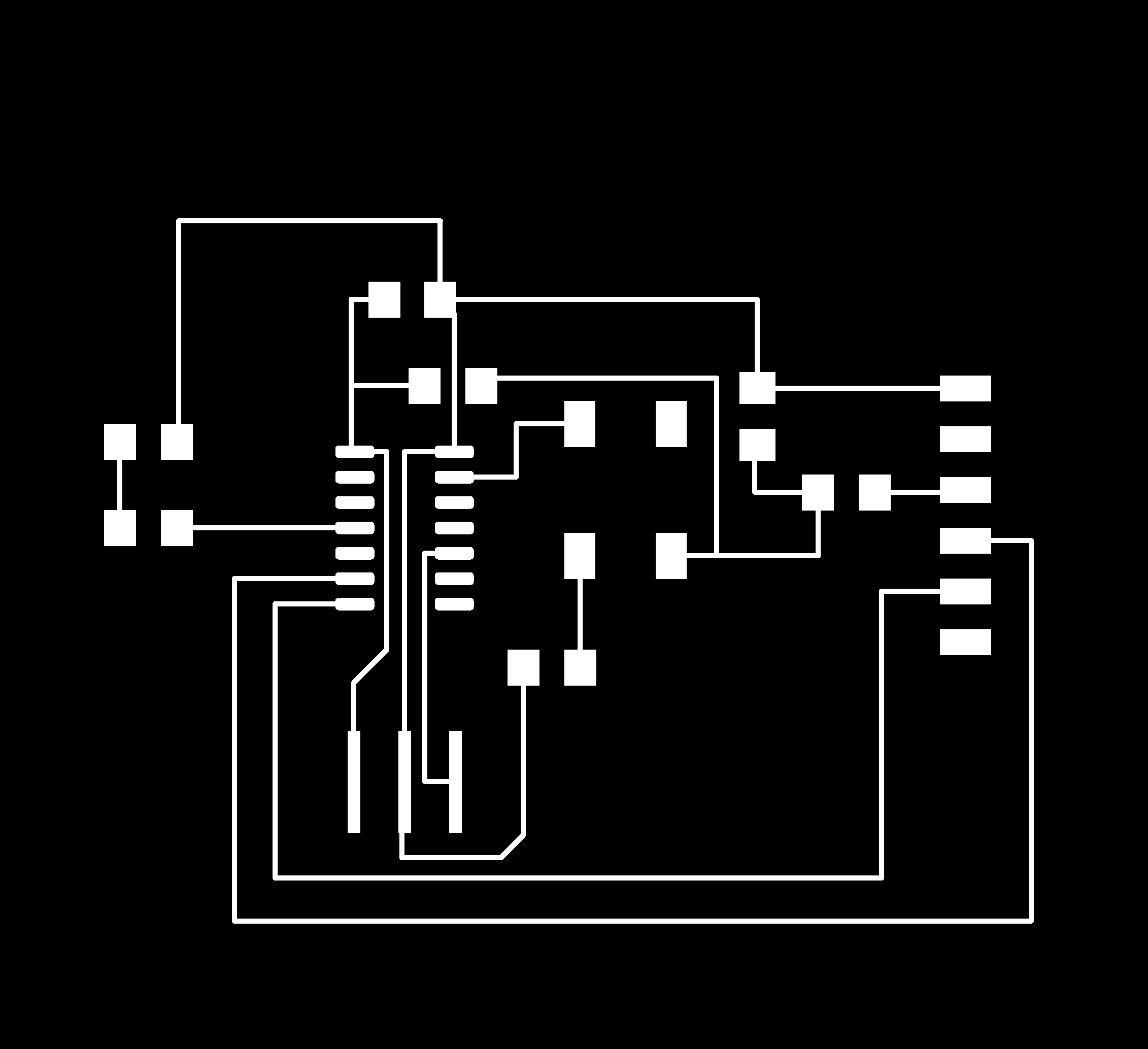
 Now you can unhide a "Top" by clicking on eye symbol to get the traces of the your board.
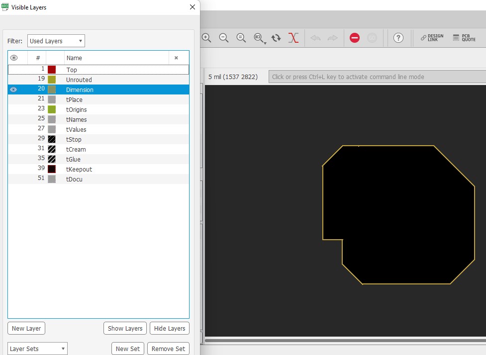
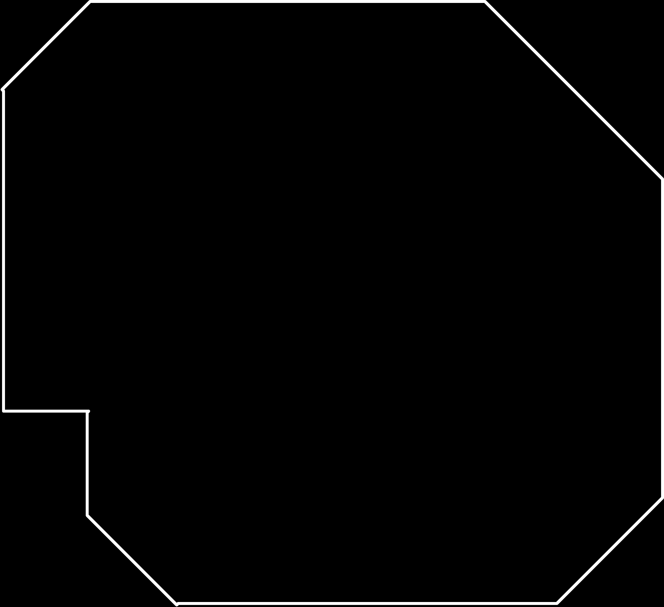
 Now to get the outline of the board, unhide "Dimension".
 Finally i have export the file in png format.
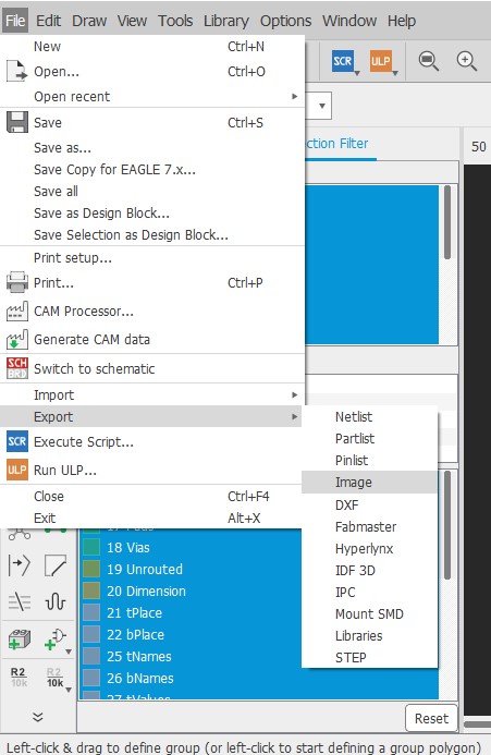 Here is my board traces and outline as shown below.
Design File.
Board Traces
Board Outline