Embedded Programming
Embedded systems programming is the programming of an embedded system in some device using the permitted programming interfaces provided by that system. EmbeddedJava is an example of a development environment for programming embedded systems that will execute Java programs.
Source from google
Group Assignment
- compare the performance and development workflows for other architectures
We only had developer kits for the Arduino Uno/Mega and the ESP32 in the lab so we were able to only compare the two.
Link to the Assignment.
Individual assignment
- browse through the data sheet for your microcontroller
- program a microcontroller development board to interact (LED/ Button) (locally) and communicate (remotely)
- extra credit: use different languages &/or development environments
They are of two types of Architecture;
1. Harvard architecture.
It is a type of digital computer architecture in which the design follows the concept of the computers with stored programs where they store the program data along with the instruction data in the very same memory. Example like computer system.
2. Von Neumann.
It is a type of digital computer architecture in which the design follows a basic concept of having separate signal paths (buses) and separate storage for data and instructions. Example like SISD (Single Instruction, Single Data).
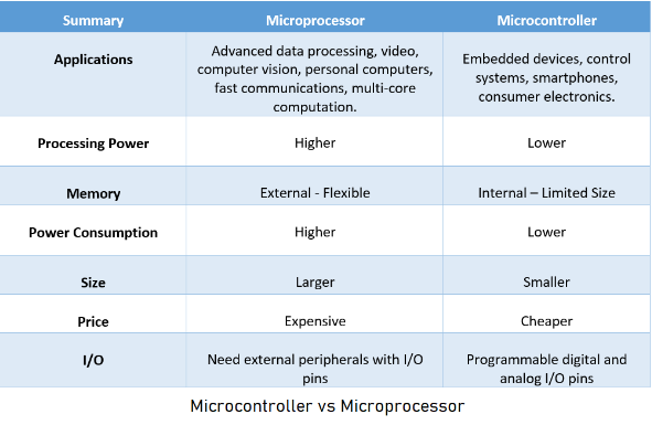
Differences between Microprocessor and Microcontroller
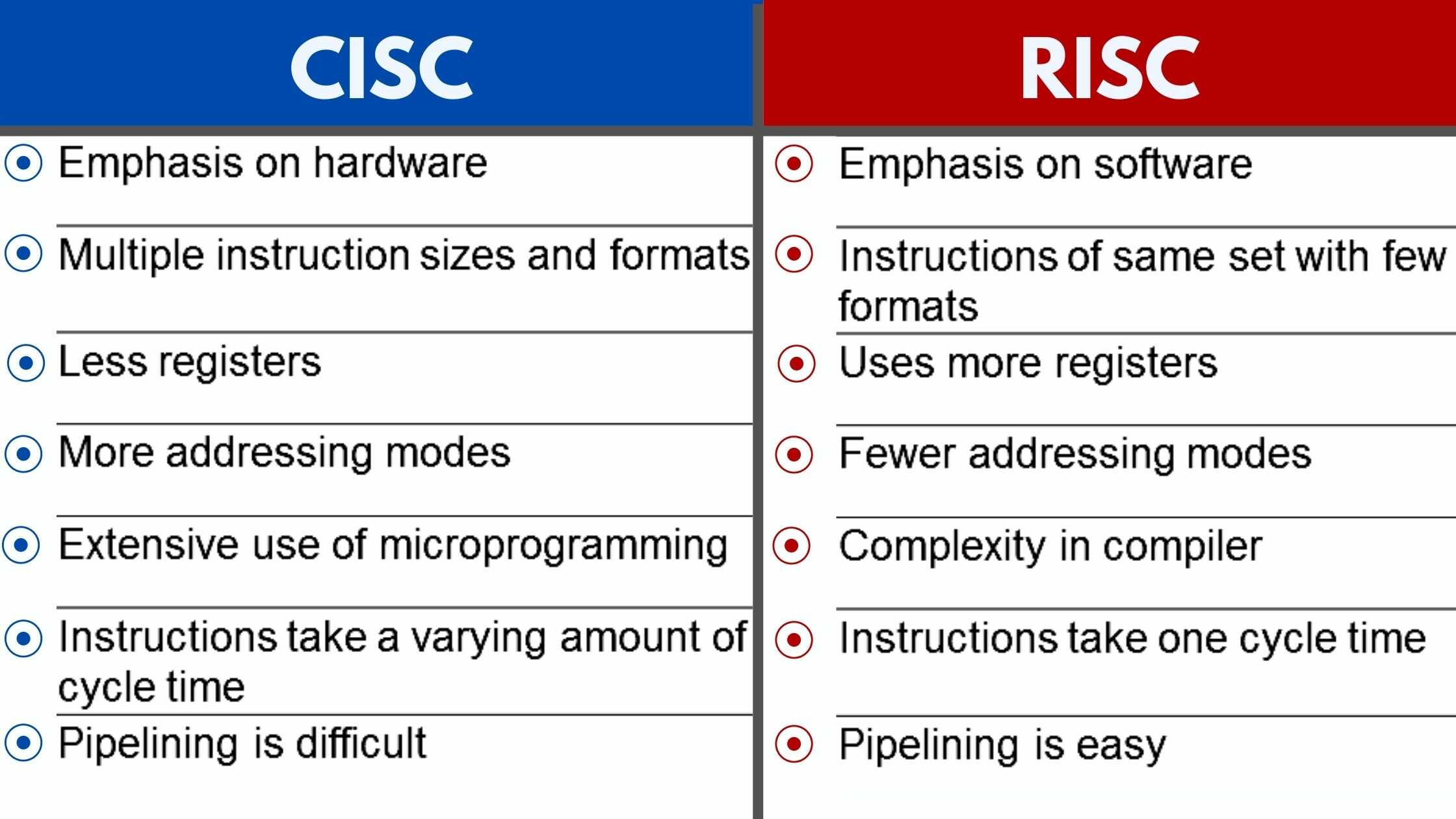
what is RISC?
RISC or Reduced Instruction Set Computer; is a type of microprocessor architecture that utilizes a small, highly-optimized set of instructions, rather than a more specialized set of instructions often found in other types of architectures.
What is CISC?
CISC stands for “Complex Instruction Set Computing.” This is a type of microprocessor design. The CISC architecture contains a large set of computer instructions that range from very simple to very complex specialized.
Difference between RISC Vs CISC
Individual Assignment
Reading a Data sheet?
For my Individual assignment i have decided to red the data sheet for a ESP-WROOM-32. So from this PDF i have write down some importance notes.
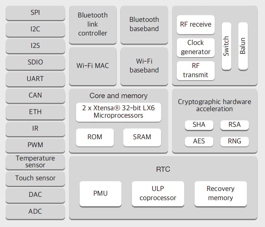
ESP-WROOM 32 is a dual core, 32-bit microcontroller module that is a part of ESP 32 series. Each CPU cores can be individually controlled. It can support clock frequency upto 240MHz and it has multiple power modes. The device has integrated WiFi, Bluetooth and bluetooth low energy(BLE). The ESP32 has multiple digital and analog I/O pins and is one of the ESP32 series of microcontrollers.The device also contains three UARTS for serial communications. The esp32 can act as SD card host controller as well as host controller for other external devices.
Pin configuration
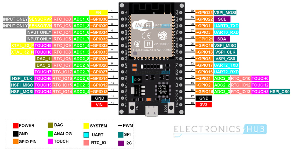
From this diagram,the module have total of 38 pins.
In module variants that have embedded QSPI PSRAM, that embed ESP32-D0WDR2-V3, IO16 is connected to the embedded PSRAM and can not be used for other functions
In the module ESP32 has five strapping pin to red the software from register.
During the chip system reset release (power-on-reset, RTC reset and brownout reset), the latches of the strapping pins sample the voltage level as strapping bits of ”0” or ”1”, and hold these bits until the chip is powered down or shut down. The strapping bits configure the device’s boot mode, the operating voltage of VDD_SDIO and other initial system settings
Each strapping pin is connected to its internal pull-up/pull-down during the chip reset.To change the strapping bit values, users can apply the external pull-down/pull-up resistances, or use the host MCU’s GPIOs to control the voltage level of these pins when powering on ESP32
ESP32 Block Diagram
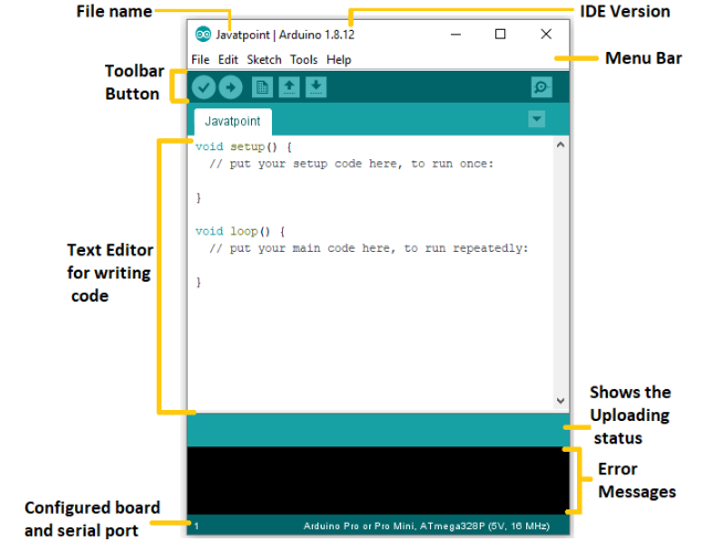
Programming with Arduino IDE
Arduino is an open-source electronics platform based on easy-to-use hardware and software.Arduino boards are able to read inputs - light on a sensor, a finger on a button, or a Twitter message - and turn it into an output - activating a motor, turning on an LED, publishing something online.The IDE application is suitable for different operating systems such as Windows, Mac OS, and Linux. It supports the programming languages C and C++.
For this weeks assignment, I set up a board with 2 LEDS, which can be controlled from arduino’s serial monitor.
Before you start programming make sure you install Arduino IDE, USB driver and Arduino ISP.
To install USB driver click here.
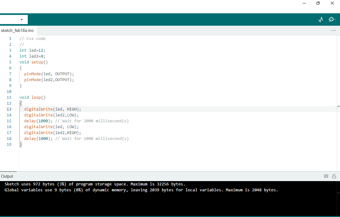
This week i havae tried out the blink program using Arduino UNO R3 with two led. So firstly i have program in tinkercad Circuit tool for circuit programming.
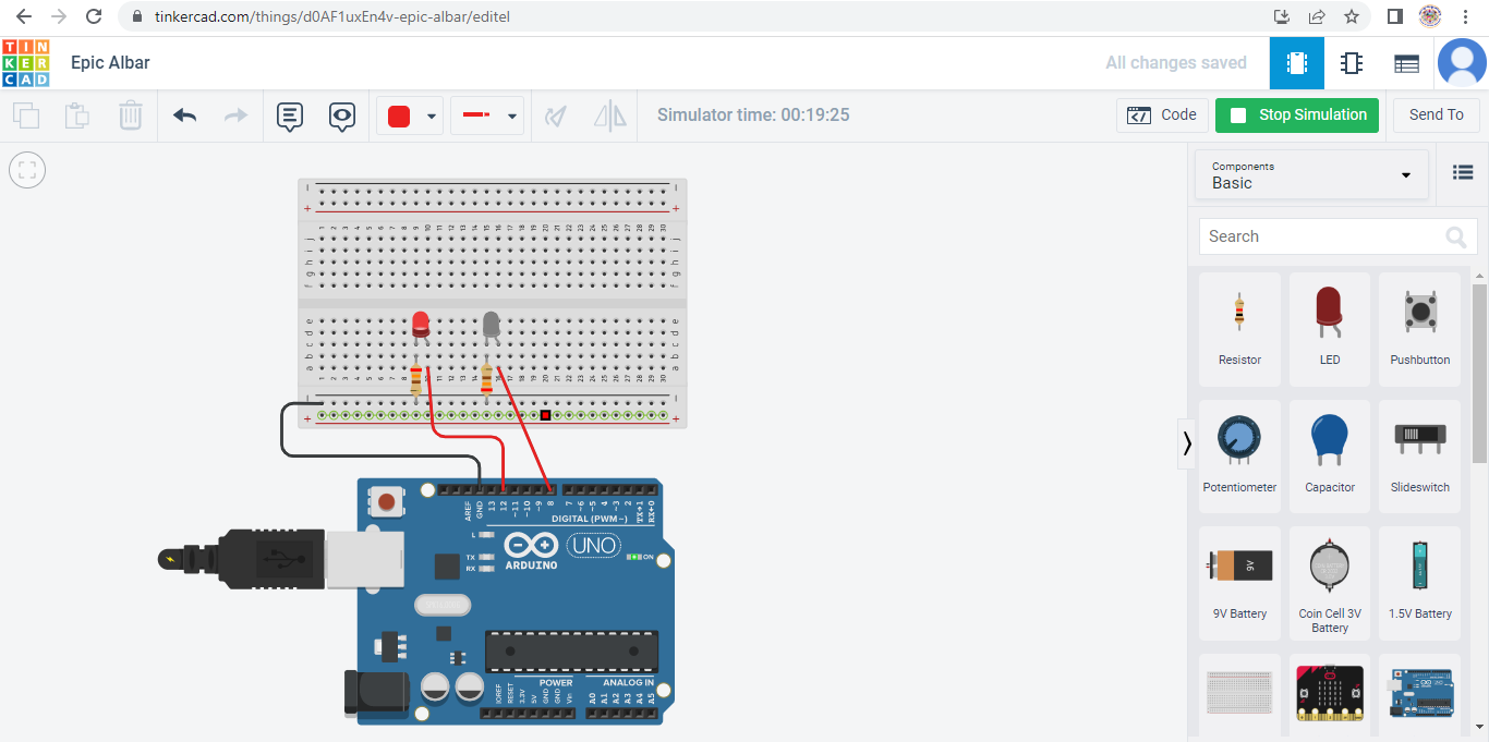
I modelled a simple uno board with two LED, 2 resistor with 230 oms and wanted it to blink. Once I had set up the model and simulated the model in TinkerCAD, I copied that code and pasted it in the Arduino IDE, and then began replicating the model in person.
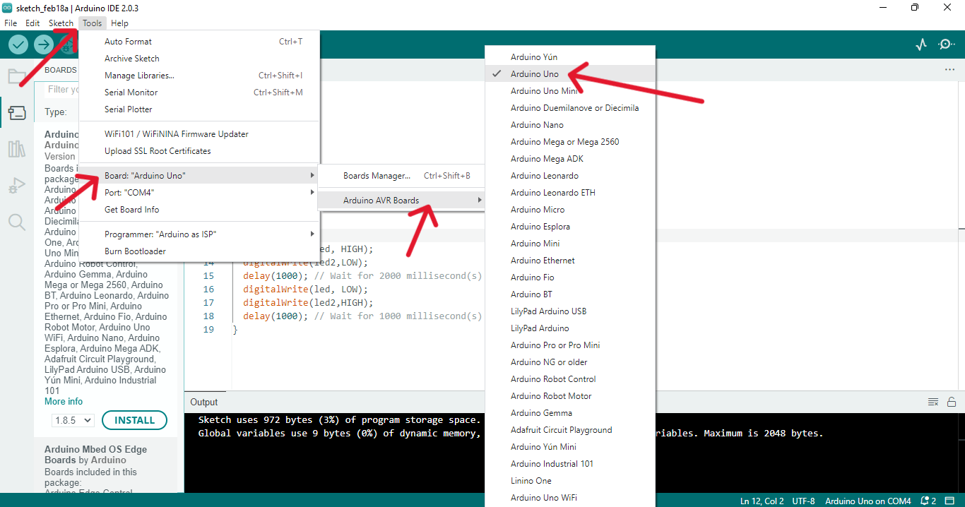
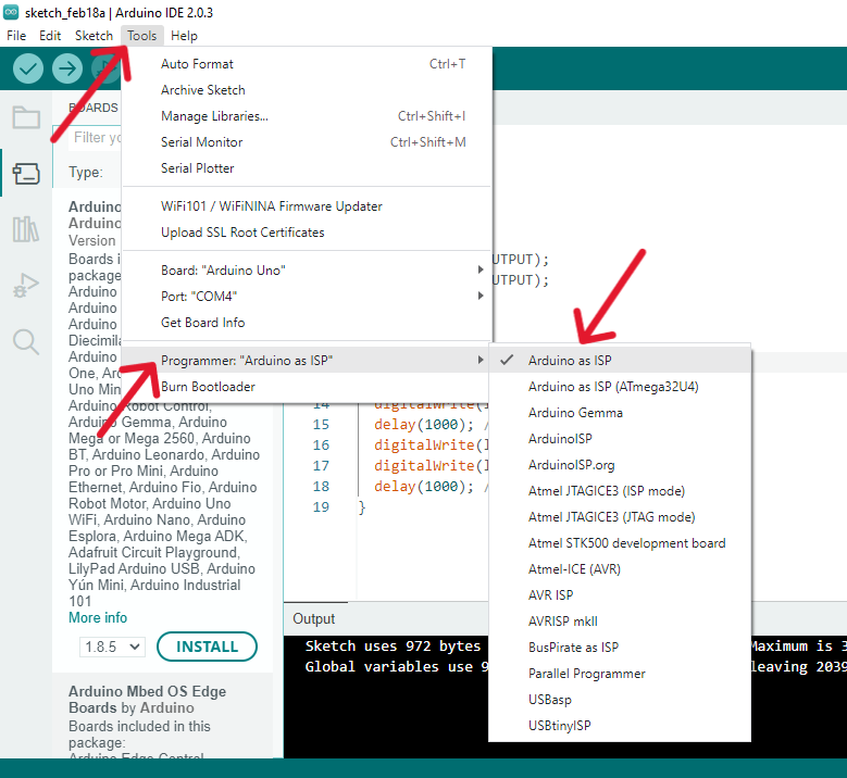
1. Before i work with Arduino IDE, Firstly i have downloaded and install Arduino IDE 2.0.3 software. And i have chose board as a Arduino uno from tool menu.
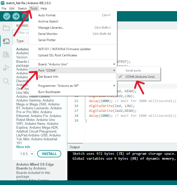
After that select the Port as COM4 (arduino uno) And Programmer as a arduino as ISP.
2. This was the code I got from TinkerCAD and i have run this code in Arduino IDE.
Hero shot for my board.
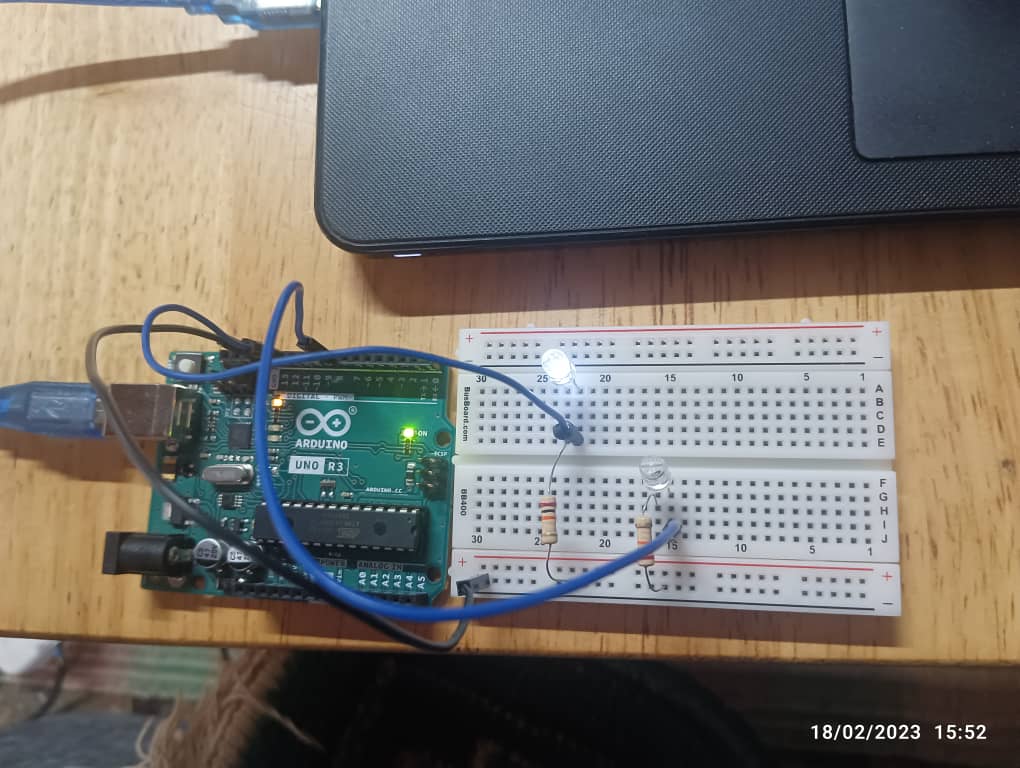
I successfully sent the code to the arduino and it worked!
setting up ESP32 with ultrasonic Distance sensor using microPython
ESP32 HC-SR04 Pinout HC-SR04 contains following four pins:
1. Vcc: Connect to ESP32 Vin pin
2. Gnd: Connect to GND
3. Trig: Pin to receive control signal from ESP32 board
4. Echo: Send back signal. Microcontroller Board receives this signal to calculate distance using time.
setting up microPython environment to work with ESP 32 and ultrasonic sensor.
For that first you have to download Thonypython IDE from Thonny.org. Since I am using windows I will be downloading the windows version and it’s also compatible for mac and linux.
Download MicroPython from here.
Then download the micropythone firmware from micropython.org according to the board you are using.
Download the firmware from here.
To Setup Ultrasonic HC-SR04 with ESP32 Using MicroPython
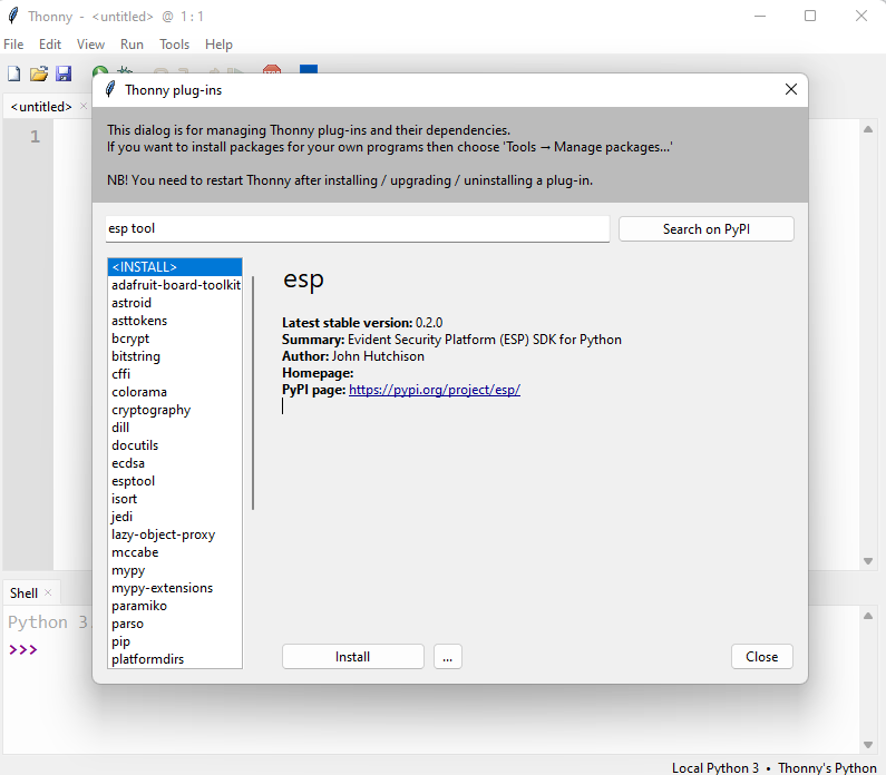
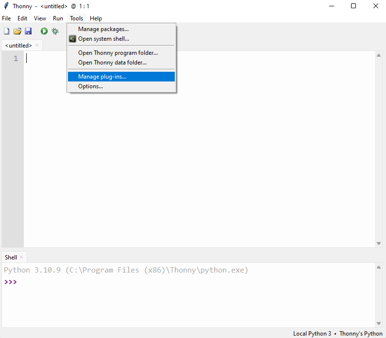
Firstly i have installed ESP tool in Thonny IDE,For that Go to tools option and click on manage plug-ins and then type ESPtool in search box and installed it. download USB driver for esp and installed on it. Link to download USB Driver.
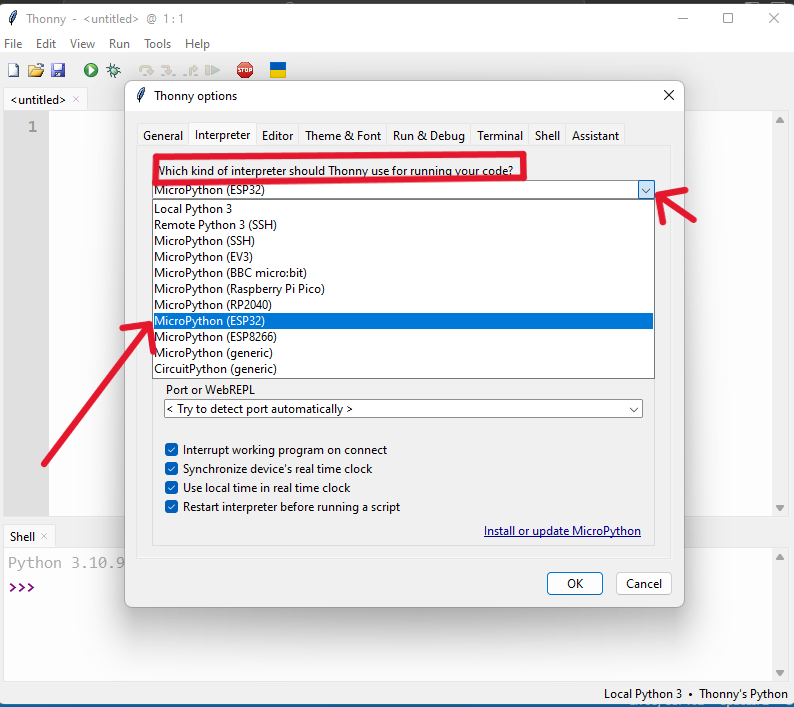
Once the esp tool is installed, go to Tools menu and click on options and select interpreter.Then there is a question asking which interpreter or device should Thonny use for running your code? for that select MicroPython (ESP32) if you are using esp32 like me or select the interpreter you are using.
And in the Port select the correct port com. In my case my device is connected to com5. If you don’t know which port com is your device connected, go to device manager and go to port and see which is the right port for your device.
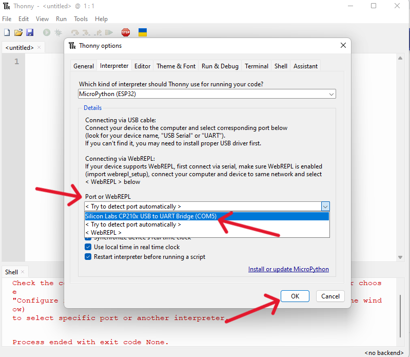
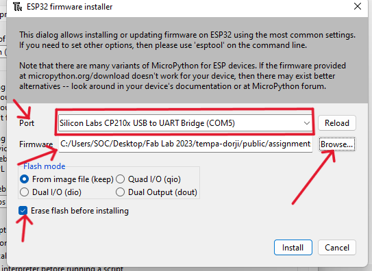
Then on the same page there is a link asking to install or update firmware.Select the same port and to add firmware click on browse and add the esp32 firmware that was downloaded earlier. Make sure the erase flash before installing box was ticked.
Now the micropython is successfully installed with esp32 development board.
Step 1: Now open Thonny IDE. Create a new file in the editor window Go to: File>New or press Ctrl + N
Step 2: Once the new file is opened, paste the following code into the Thonny IDE editor window. As i have saved my coding in notepad.
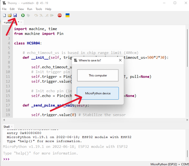
Step 2: After writing the library code inside the editor window now we have to save it inside the MicroPython device. Save the ultrasonic library file with name hcsr04.py and click OK.
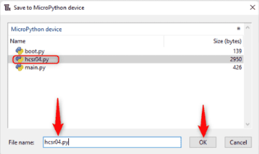
Now the ultrasonic hcsr04 sensor library is successfully added to the ESP32 board. Now we can call library functions inside code to measure distance of different objects.
Code for Ultrasonic Sensor Using MicroPython
For ultrasonic sensor code create a new file (Ctrl + N). In the editor window, enter the code given below and save it inside the main.py or boot.py file. This code will print the distance of any object that comes in front of HC-SR04.
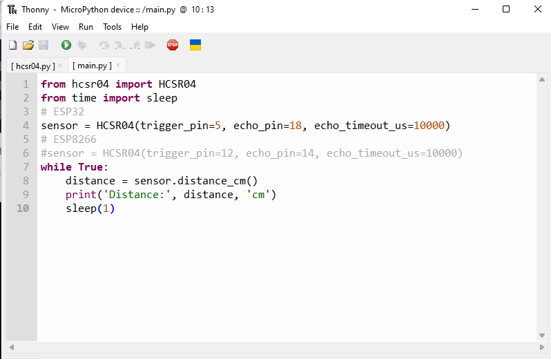
Code started by calling important libraries such as HCSR04 and time library along with sleep to give delays.
After writing and saving code inside the MicroPython device, I now run the ultrasonic sensor main.py file code. Click the play button or press F5.
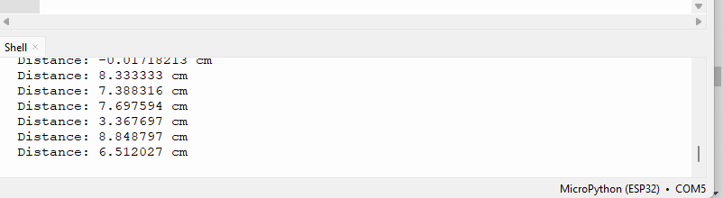
Now place an object near the ultrasonic sensor and check the measured distance on the serial monitor window of Arduino IDE. Object distance is shown in the shell terminal.
Output video of Ultrasonic Sensor
Failure of this week!!
During this week i have done a big mistake while git push, as i have commit 9 times push to repro with more than 10MB and also created a new directory file in my same folder as a duplicate.so to solve this issue i ask help from Mr.Ricko and Mr. Julian to solve my issue.
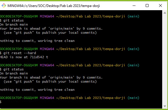
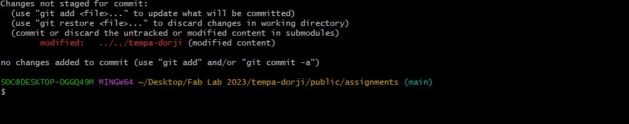
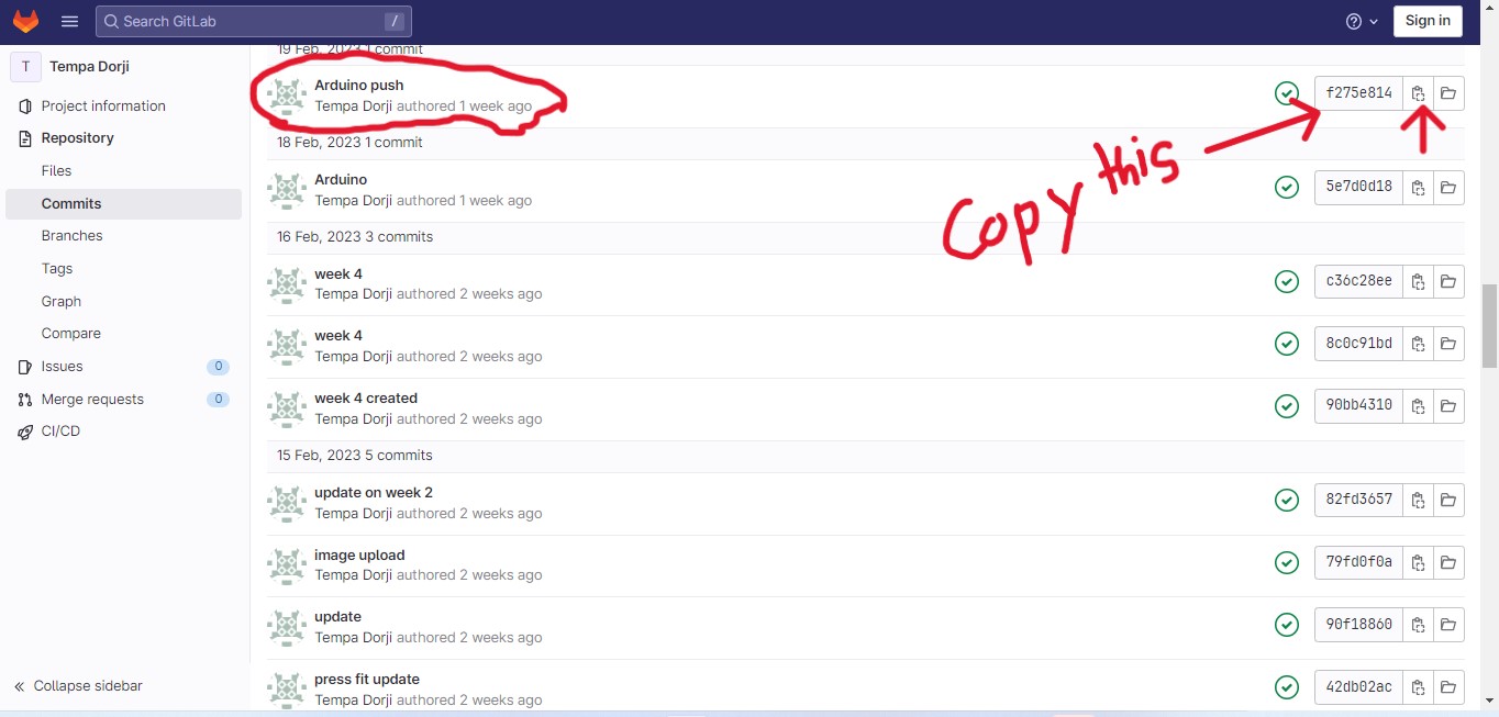
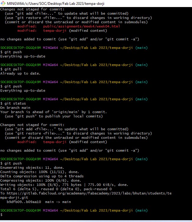
For information, how the command sequence should be;